Posted on

Mitsubishi Colt 2004-2011 Factory Service & Shop Manual


Download Link

INSTANT DOWNLOAD (add to cart)


Mitsubishi Colt 2004-2011 Factory Service & Shop Manual
Complete workshop & service manual with electrical wiring diagrams for Mitsubishi Colt 2004-2011. It’s the same service manual used by dealers that guaranteed to be fully functional and intact without any missing page.

This Mitsubishi Colt 2004-2011 service & repair manual (including maintenance, overhaul, disassembling & assembling, adjustment, tune-up, operation, inspecting, diagnostic & troubleshooting…) is divided into different sections. Each section covers a specific component or system with detailed illustrations. A table of contents is placed at the beginning of each section. Pages are easily found by category, and each page is expandable for great detail. The printer-ready PDF documents work like a charm on all kinds of devices.

EXCERPT:
11B_Engine_Mechanical_(135).pdf
11A_Engine_Mechanical_(134).pdf
42_Body.pdf
00_General.pdf
13A_Multipoint_Fuel_Injection.pdf
35C_Traction_Control,_Active_Stability_Control_System.pdf
12_Engine_Lubrication.pdf
54A_Chassis_Electrical.pdf
52B_Suplemental_Restraint_System_(SRS).pdf
52A_Interior.pdf
37A_Power_Steering.pdf
54C_Controller_Area_Network_(CAN).pdf
55_Heater,_Air_Conditioner_and_Ventilation.pdf
35A_Servise_Brakes.pdf
37_Power_Steering.pdf
54B_Local_Interconect_Network_(LIN).pdf
35B_Four-Wheel_Anti-Skid_Brake_System_(4ABS).pdf
51_Exterior.pdf
22B_Automated_Manual_Transmission.pdf
13C_Fuel_Supply.pdf
15_Intake_and_Exhaust.pdf
14_Engine_Cooling.pdf
33A_Front_Suspension.pdf
21_Clutch.pdf
22A_Manual_Transmission.pdf
33_Front_Suspension.pdf
16_Engine_Electrical.pdf
32_Power_Plant_Mount.pdf
13B_Fuel_Supply.pdf
26_Front_Axle.pdf
17_Engine_and_Enmission_Control.pdf
34_Rear_Suspension.pdf
31_Wheel_and_Tyre.pdf
36_Parking_Brake.pdf
27_Rear_Axle.pdf
52_Interior_and_Suplemental_System.pdf
54_Chassis_Electrical.pdf
35_Service_Brakes.pdf
22_Manual_Transmission.pdf
11_Engine.pdf
13_Fuel.pdf
BRM_Colt_Z3_(ZM)

AIR BAG MODULE AND SEAT BELT PRE-TENSIONER DISPOSAL PROCEDURES
Before disposing of an air bag or a vehicle equipped with an air bag, follow the procedures below to deploy the air bag.
UNDERPLAYED AIR BAG MODULE DISPOSAL WARNING
• If the vehicle is to be scrapped or otherwise disposed of, deploy the air bags and operate the seat belt pre-tensioner inside the vehicle. If the vehicle will continue to be used and only the air bag modules and seat belt pre-tensioner are to be disposed of, deploy the air bags and operate the seat belt pre-tensioner outside the vehicle.
• Since a large amount of smoke is produced when the air bag is deployed and the seat belt pre-tensioner is operated, avoid residential areas whenever possible.
• Since there is loud noise when the air bags are deployed and when the seat belt pre-tensioner are operated, avoid residential areas whenever possible. If anyone is nearby, give warning of the impending noise.
• Suitable ear protection should be worn by personnel performing these procedures or by people in the immediate area.
DEPLOYMENT INSIDE THE VEHICLE (WHEN DISPOSING OF A VEHICLE)

1. Move the vehicle to an isolated spot.
DANGER
Wait at least 60 seconds after the disconnection of the battery cable before any further job (Refer to P.52B-5).
2. Disconnect the negative and positive battery cables from the battery terminals, and then remove the battery from the vehicle.

Posted on

Mitsubishi Carisma 1995-2003 Factory Service & Shop Manual


Download Link

INSTANT DOWNLOAD (add to cart)


Mitsubishi Carisma 1995-2003 Factory Service & Shop Manual
Complete workshop & service manual with electrical wiring diagrams for Mitsubishi Carisma 1995-2003. It’s the same service manual used by dealers that guaranteed to be fully functional and intact without any missing page.

This Mitsubishi Carisma 1995-2003 service & repair manual (including maintenance, overhaul, disassembling & assembling, adjustment, tune-up, operation, inspecting, diagnostic & troubleshooting…) is divided into different sections. Each section covers a specific component or system with detailed illustrations. A table of contents is placed at the beginning of each section. Pages are easily found by category, and each page is expandable for great detail. The printer-ready PDF documents work like a charm on all kinds of devices.

MAKE: Mitsubishi
YEAR: 1995 1996 1997 1998 1999 2000
MODEL: Carisma
LANGUAGE: EN/ES/SV
Format: PDF

EXCERPT:
ON-VEHICLE SERVICE
LASH ADJUSTER CHECK
If an abnormal noise (knocking) that seems to be coming from the lash adjuster is heard after starting the engine and does not stop, carry out the following check.
NOTE
(1) The abnormal noise which is caused by a problem with the lash adjusters is generated after the engine is started, and will vary according to the engine speed. However, this noise is not related to the actual engine load.
Because of this, if the noise does not occur immediately after the engine is started, if it does not change in accordance with the engine speed, or if it changes in accordance with the engine load, the source of the noise is not the lash adjusters.
(2) If there is a problem with the lash adjusters, the noise will almost never disappear, even if the engine has been run at idle to let it warm up.
The only case where the noise might disappear is if the oil in the engine has not been looked after properly and oil sludge has caused the lash adjusters to stick.

Posted on

Mitsubishi ASX/RVR/Outlander Sport 2010-2016 Workshop Repair & Service Manual


Download Link

INSTANT DOWNLOAD (add to cart)


Mitsubishi ASX/RVR/Outlander Sport 2010-2016 Workshop Repair & Service Manual

Complete digital official shop manual contains service, maintenance, and troubleshooting information for the 2010-2016 Mitsubishi ASX, RVR, Outlander Sport. Diagnostic and repair procedures are covered in great detail to repair, maintain, rebuild, refurbish or restore your vehicle like a professional mechanic in local service/repair workshop. This cost-effective quality manual is 100% complete and intact as should be without any missing pages. It is the same factory shop manual used by dealers that guaranteed to be fully functional to save your precious time.

This manual for 2010-2016 Mitsubishi ASX, RVR, Outlander Sport is divided into different sections. Each section covers a specific component or system and, in addition to the standard service procedures, includes disassembling, inspecting, and assembling instructions. A table of contents is placed at the beginning of each section. Pages are easily found by category, and each page is expandable for great detail. It is in the cross-platform PDF document format so that it works like a charm on all kinds of devices. You do not need to be skilled with a computer to use the manual.

EXCERPT:
2011 ENGINE Engine Cooling – Outlander Sport & RVR
ENGINE COOLANT CONCENTRATION TEST
CAUTION: Engine coolant of less than 30% concentration has a less rust-proof effect. In a concentration of over 60%, the antifreeze effect and engine cooling performance of the engine coolant are deteriorated, causing a detrimental effect on the engine. Therefore, observe the service concentration range without fail.
 Use the Dia Queen Super Long Life Coolant Premium without adding water because the concentration is pre-adjusted to 50%.
Using a hydrometer, check if the engine coolant concentration is within the standard value range.
Standard value: 30 to 60% (service concentration range)
WATER PUMP COOLANT LEAK CHECK
Even when the water pump is normal, a residue of the engine coolant draining may be found on the drain hole, the vapor hole and the installation surface of the water pump. If a residue of the engine coolant draining is found, check the water pump leakage by following method.
1. Wipe off the residue of the engine coolant draining on the water pump.
WARNING: Make sure that the engine coolant is cold when removing the radiator cap.
2. Remove the radiator cap.
CAUTION: Do not pressures 100 kPa (15 psi) or more.
3. Install the radiator tester and pressures at 100 kPa (15 psi.)
4. Hold the pressurized state for 20 minutes, and check that the engine coolant leakage from the drain hole, the vapor hole or the installation surface of the water pump.
5. Remove the radiator tester, and install the radiator cap.
6. Warm up the engine, let it idle for 20 minutes and stop it.
7. After stopping the engine, and check that the engine coolant leakage from the drain hole, the vapor hole or the installation surface of the water pump.
8. If the engine coolant leakage is found in step 4 or 7, replace the water pump (Refer to REMOVAL AND INSTALLATION ).
Fig. 12: Checking For Engine Coolant Leakage
COOLING FAN RELAY REPLACEMENT
Fig. 13: Precaution For Cooling Fan Relay
1. Remove the relay by hand. If it cannot be removed by hand, pinch the part “A” (shown in illustration) with long-nose pliers and remove the relay.
2. Install the new relay by hand.
CAUTION: Basically, remove or install the relay by hand. If the center of relay has been pinched by pliers, it can be damaged.

Posted on


Download Link

INSTANT DOWNLOAD (add to cart)


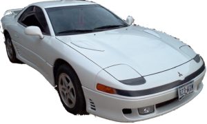
Complete workshop & service manual with electrical wiring diagrams for Mitsubishi 3000GT 1991-1999. It’s the same service manual used by dealers that guaranteed to be fully functional and intact without any missing page.

This Mitsubishi 3000GT 1991-1999 service & repair manual (including maintenance, overhaul, disassembling & assembling, adjustment, tune-up, operation, inspecting, diagnostic & troubleshooting…) is divided into different sections. Each section covers a specific component or system with detailed illustrations. A table of contents is placed at the beginning of each section. Pages are easily found by category, and each page is expandable for great detail. The printer-ready PDF documents work like a charm on all kinds of devices.

MAKE: Mitsubishi
YEAR: 1991 1992 1993 1994 1995 1996 1997 1998 1999
MODEL: 3000GT, 3000GT Spyder (a.k.a. Mitsubishi GTO, Dodge Stealth)

EXCERPT:
REMOVAL & INSTALLATION
FUEL PRESSURE RELEASE
1. To relieve fuel pressure, remove fuel pump cover in luggage compartment. Disconnect fuel pump harness connector at fuel tank. Start engine. After engine stalls, turn ignition switch to OFF position. Disconnect negative battery terminal. Reconnect fuel pump harness.
2. Wrap shop towels around fuel return and high pressure hoses to prevent fuel splashing on engine.
Disconnect fuel return hose and high pressure fuel hose to drain any residual fuel.
ENGINE
Removal (Eclipse & Galant)
1. Remove hood. Release fuel system pressure. See FUEL PRESSURE RELEASE. Drain cooling system.
Remove air cleaner assembly. Remove heater and radiator hoses. Remove radiator. Remove front exhaust pipe.
2. Label and disconnect all vacuum hoses. Label and unplug all electrical connections and harnesses from engine. Remove starter, oil pressure switch and generator connectors. Cover fuel hose with shop towel, and disconnect high pressure fuel hose. Disconnect fuel return hose. Remove accessory drive belts.
Remove A/C compressor from compressor bracket with hose attached.
3. Remove power steering oil pump from engine with hose attached. Remove engine mount bracket and engine mount stopper. Ensure all hoses and wires are disconnected, and set aside. Attach engine hoist to engine. Remove engine from engine compartment.
Installation (Eclipse & Galant)
To install, reverse removal procedure. Tighten bolts and nuts to specification. See TORQUE SPECIFICATIONS.

Posted on

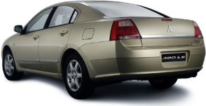
Mitsubishi 380 2005-2007 Factory Service & Shop Manual


Download Link

INSTANT DOWNLOAD (add to cart)


Complete workshop & service manual with electrical wiring diagrams for Mitsubishi 380 2005-2007. It’s the same service manual used by dealers that guaranteed to be fully functional and intact without any missing page.

This Mitsubishi 380 2005-2007 service & repair manual (including maintenance, overhaul, disassembling & assembling, adjustment, tune-up, operation, inspecting, diagnostic & troubleshooting…) is divided into different sections. Each section covers a specific component or system with detailed illustrations. A table of contents is placed at the beginning of each section. Pages are easily found by category, and each page is expandable for great detail. The printer-ready PDF documents work like a charm on all kinds of devices.

GROUP INDEX
General . . . . . . . . . . . . . . . . . . . . . . . 00
Engine . . . . . . . . . . . . . . . . . . . . . . . . 11
Engine Lubrication . . . . . . . . . . . . . . 12
Fuel . . . . . . . . . . . . . . . . . . . . . . . . . . 13
Engine Cooling . . . . . . . . . . . . . . . . . 14
Intake and Exhaust. . . . . . . . . . . . . . 15
Engine Electrical. . . . . . . . . . . . . . . . 16
Engine and Emission Control . . . . . 17
Clutch. . . . . . . . . . . . . . . . . . . . . . . . . 21
Manual Transmission. . . . . . . . . . . . 22
Automatic Transmission . . . . . . . . . 23
Front Axle . . . . . . . . . . . . . . . . . . . . . 26
Rear Axle . . . . . . . . . . . . . . . . . . . . . . 27
Wheel and Tyre . . . . . . . . . . . . . . . . . 31
Power Plant Mount . . . . . . . . . . . . . . 32
Front Suspension . . . . . . . . . . . . . . . 33
Rear Suspension . . . . . . . . . . . . . . . 34
Service Brakes . . . . . . . . . . . . . . . . . 35
Parking Brakes . . . . . . . . . . . . . . . . . 36
Steering . . . . . . . . . . . . . . . . . . . . . . . 37
Body. . . . . . . . . . . . . . . . . . . . . . . . . . 42
Exterior . . . . . . . . . . . . . . . . . . . . . . . 51
Interior and SRS . . . . . . . . . . . . . . . . 52
Chassis Electrical . . . . . . . . . . . . . . . 54
Heater, A/C and Ventilation . . . . . . . 55
Component Locations . . . . . . . . . . . 70
Configuration Diagrams. . . . . . . . . . 80
Circuit Diagrams. . . . . . . . . . . . . . . . 90

EXCERPT:
REMOVAL SERVICE POINT
.< > RADIATOR LOWER HOSE DISCONNECTION
Make mating marks on the radiator hose and the hose clamp.
Disconnect the radiator hose.
INSTALLATION SERVICE POINTS
.>>A< < THERMOSTAT INSTALLATION CAUTION Make absolutely sure that no oil adheres to the rubber ring of the thermostat. Also do not fold or scratch the rubber ring during installation. Install the thermostat so that the jiggle valve is facing straight up. Be careful not to fold or scratch the rubber ring. .>>B<< RADIATOR LOWER HOSE CONNECTION 1. Insert each hose as far as the projection of the water inlet fitting. 2. Align the mating marks on the radiator hose and hose clamp, and then connect the radiator hose.