Posted on

Hitachi EX1000, EX1100 Excavator Factory Service & Shop Manual


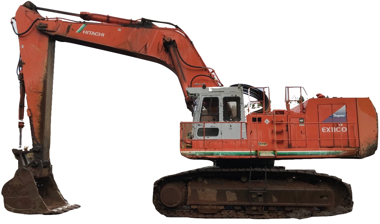
Pages from W142E00 – Hitachi EX1100-3 Excavator Workshop Manual

MHITEX1100OPES.zip
Price: $29.99 USD

Complete workshop & service manual with electrical wiring diagrams for Hitachi EX1000, EX1100, EX1100-3 Excavator. It’s the same service manual used by dealers that guaranteed to be fully functional and intact without any missing page.

This Hitachi EX1000, EX1100, EX1100-3 Excavator service & repair manual (including maintenance, overhaul, disassembling & assembling, adjustment, tune-up, operation, inspecting, diagnostic & troubleshooting…) is divided into different sections. Each section covers a specific component or system with detailed illustrations. A table of contents is placed at the beginning of each section. Pages are easily found by category, and each page is expandable for great detail. The printer-ready PDF documents work like a charm on all kinds of devices.

FILELIST:
KM123E01 – Hitachi EX1100 Excavator Technical Shop Manual (Service & Repair).pdf
KM10700 – Hitachi EX1000 Excavator Technical Shop Manual (Service & Repair) 1 of 2.pdf
KM10700 – Hitachi EX1000 Excavator Technical Shop Manual (Service & Repair) 2 of 2.pdf
T142E00 – Hitachi EX1100-3 Excavator Technical Manual.pdf
TO18EE-00 – Hitachi EX1200-5C Excavator Technical Manual (Operational Principle).pdf
W142E00 – Hitachi EX1100-3 Excavator Workshop Manual.pdf
EM17E21 – Hitachi EX1100-3 Excavator Operator’s Manual.pdf
EM178EN17 – Hitachi EX1100 Excavator Operator’s Manual.pdf
EM17818 – Hitachi EX1100 Excavator Operator’s Manual.pdf
Hitachi EX1200 5 & 6 Excavator Pin & Buses.pdf

EXCERPT:
UPPERSTRUCTURE / Pilot Shut-off Valve
Disassemble Pilot Shut-Off Valve
Be sure to thoroughly read Precautions for Disassembly and Assembly on page W01-01-01 before starting disassembly.
1. Remove retaining ring (1) and washer (2) and pull out spool (11).
2. Remove spring pin (9) from spool (11), then remove lever (10).
NOTE: Mark spool (11) and lever (10) for alignment when installing.
3. Remove washer (7), retaining ring (8) from spool (11).
4. Remove backup rings (3), (6), O-ring (4) and (5) from body (14).

Posted on

Hitachi EX700, EX750-5, EX800H-5 Hydraulic Excavator Factory Service & Shop Manual


Pages from W162E00 – Hitachi EX750-5, EX800H-5 Hydraulic Excavator Workshop Manual

MHITEX700EX800OPES.zip
Price: $29.99 USD

Complete workshop & service manual with electrical wiring diagrams for Hitachi EX700, EX750-5, EX800H-5 Hydraulic Excavator. It’s the same service manual used by dealers that guaranteed to be fully functional and intact without any missing page.

This Hitachi EX700, EX750-5, EX800H-5 Hydraulic Excavator service & repair manual (including maintenance, overhaul, disassembling & assembling, adjustment, tune-up, operation, inspecting, diagnostic & troubleshooting…) is divided into different sections. Each section covers a specific component or system with detailed illustrations. A table of contents is placed at the beginning of each section. Pages are easily found by category, and each page is expandable for great detail. The printer-ready PDF documents work like a charm on all kinds of devices.

FILELIST:
K0205L00 – Hitachi EX750-5, EX800H-5 Hydraulic Excavator Check Sheets – Ultrasonic (UT) Inspection – Loader Front.pdf
K021200 – Hitachi EX750-5, EX800H-5 Hydraulic Excavator Check Sheets – Recommended Preventive Service Program.pdf
KM11700 – Hitachi EX700 Hydraulic Excavator Service Manual – Loader Front Atiachment.pdf
KO205B00 – Hitachi EX750-5, EX800H-5 Hydraulic Excavator Check Sheets – Ultrasonic (UT) Inspection – Backhoe Front.pdf
KO205B01 – Hitachi EX750-5, EX800H-5 Hydraulic Excavator Check Sheets – Visual Inspection – Backhoe Front.pdf
KO205L01 – Hitachi EX750-5, EX800H-5 Hydraulic Excavator Check Sheets – Visual Inspection – Loader Front.pdf
KO17700 – Hitachi EX750-5, EX800H-5 Hydraulic Excavator Assembly Procedure Manual.pdf
KO18700 – Hitachi EX750-5, EX800H-5 Hydraulic Excavator Check Sheets – Daily (10HR) and Weekly (50HR) Maintenance.pdf
KO18800 – Hitachi EX750-5, EX800H-5 Hydraulic Excavator Check Sheets – Monthly (250HR) Maintenance.pdf
KO19200 – Hitachi EX750-5, EX800H-5 Hydraulic Excavator Check Sheets – Completed Assembly Manual.pdf
T162E00 – Hitachi EX750-5, EX800H-5 Hydraulic Excavator Technical Manual.pdf
TO162E01 – Hitachi EX750-5, EX800H-5 Hydraulic Excavator Technical Manual (Operational Principle).pdf
TT162E01 – Hitachi EX750-5, EX800H-5 Hydraulic Excavator Technical Manual (Troubleshooting Manual).pdf
TT162E01CIR – Hitachi EX750-5, EX800H-5 Hydraulic Excavator Electrical Circuit Diagrams.pdf
W162E00 – Hitachi EX750-5, EX800H-5 Hydraulic Excavator Workshop Manual.pdf
EM17C12 – Hitachi EX750-5, EX800H-5 Hydraulic Excavator Operator’s Manual.pdf
EM17C31 – Hitachi EX750-5, EX800H-5 Hydraulic Excavator Operator’s Manual.pdf
EM17C51 – Hitachi EX750-5, EX800H-5 Hydraulic Excavator Operator’s Manual.pdf
EM17224 – Hitachi EX700 Hydraulic Excavator Operator’s Manual.pdf

EXCERPT:
UNDERCARRIAGE / Travel Device
Disassemble Brake Valve
Be sure to thoroughly read Precautions for Disassembly and Assembly on page W1-1-1 before starting the disassembly work.
1. Remove socket bolts (9) (8 used). : 10 mm
2. Remove cap (5) from body (13).
3. Remove O-rings (6) (2 used) and backup rings (7) (2 used) from cap (5).
4. Loosen plugs (1) (2 used) to remove springs (3) (2 used) and balls (4) (2 used) from cap (5). : 14 mm
5. Remove spring seats (21) (2 used), (19) (2 used) and springs (20) (2 used) from cap (5).
6. Remove plunger (12) from body (13).
7. Remove plugs (18) (2 used). : 14 mm
8. Remove springs (16) (2 used) and check valves (15) (2 used) from body (13).
IMPORTANT: Place soft protectors, such as cloth, between the vise and plunger (12) so as not to damage plunger (12).
9. Insert a metal bar into the hole provided on the stepped part of plunger (12).
Note that the metal bar is used to prevent plunger (12) from turning when removing plugs (10) (2 used). Put plunger (12) in a vise.
10. Remove plugs (10) (2 used) from plunger (12). : 19 mm

Posted on

Hitachi EX550-3, EX550-3C, EX550-5, EX600H-5 Hydraulic Excavators Factory Service & Shop Manual


Pages from W116E00 – Hitachi EX550-3, EX550-3C Hydraulic Excavator Workshop Manual

MHITEX550EX600OPES.zip
Price: $29.99 USD

Complete workshop & service manual with electrical wiring diagrams for Hitachi EX550-3, EX550-3C, EX550-5, EX600H-5 Hydraulic Excavators. It’s the same service manual used by dealers that guaranteed to be fully functional and intact without any missing page.

This Hitachi EX550-3, EX550-3C, EX550-5, EX600H-5 Hydraulic Excavators service & repair manual (including maintenance, overhaul, disassembling & assembling, adjustment, tune-up, operation, inspecting, diagnostic & troubleshooting…) is divided into different sections. Each section covers a specific component or system with detailed illustrations. A table of contents is placed at the beginning of each section. Pages are easily found by category, and each page is expandable for great detail. The printer-ready PDF documents work like a charm on all kinds of devices.

FILELIST:
T116E00 – Hitachi EX550-3, EX550-3C Hydraulic Excavator Technical Manual.pdf
T167E00 – Hitachi EX550-5, EX600H-5 Hydraulic Excavator Technical Manual.pdf
W116E00 – Hitachi EX550-3, EX550-3C Hydraulic Excavator Workshop Manual.pdf
W167E00 – Hitachi EX550-5, EX600H-5 Hydraulic Excavator Workshop Manual.pdf
EM17A11 – Hitachi EX550, EX550LC, EX550H, EX550LCH Hydraulic Excavator Operator’s Manual.pdf
EM17B11 – Hitachi EX550-3, EX550LC-3, EX600H-3, EX600LCH-3 Hydraulic Excavator Operator’s Manual.pdf
EM17BEN11 – Hitachi EX550-3, EX550LC-3, EX600H-3, EX600LCH-3 Hydraulic Excavator Operator’s Manual.pdf
EM17H12 – Hitachi EX550-3, EX550LC-3, EX600H-3, EX600LCH-3 Hydraulic Excavator Operator’s Manual.pdf

EXCERPT:
UPPERSTRUCTURE I Swing Device
Before assembling, wash each part with clean solvent and dry with compressed air. Apply clean hydraulic oil to the internal parts before installing them.
Be sure to replace o-rings, oil seals and needle bearings with new ones.
1. Install inner race of bearing (34) to shaft (35) using tool (ST 2318).
2. Install retaining ring (28) to casing (31).

Posted on

Hitachi EX400, EX450 Hydraulic Excavator Factory Service & Shop Manual

OLYMPUS DIGITAL CAMERA

Pages from T111E00 – Hitachi EX400-3, EX400-3C Hydraulic Excavator Technical Manual


INSTANT DOWNLOAD


Complete workshop & service manual with electrical wiring diagrams for Hitachi EX400, EX400-3, EX400-3C, EX400-5, EX400LC, EX400LC-5, EX450LC-5 Hydraulic Excavator. It’s the same service manual used by dealers that guaranteed to be fully functional and intact without any missing page.

This Hitachi EX400, EX400-3, EX400-3C, EX400-5, EX400LC, EX400LC-5, EX450LC-5 Hydraulic Excavator service & repair manual (including maintenance, overhaul, disassembling & assembling, adjustment, tune-up, operation, inspecting, diagnostic & troubleshooting…) is divided into different sections. Each section covers a specific component or system with detailed illustrations. A table of contents is placed at the beginning of each section. Pages are easily found by category, and each page is expandable for great detail. The printer-ready PDF documents work like a charm on all kinds of devices.

FILE LIST:
KM10800 – Hitachi EX400, EX400LC Hydraulic Excavator Technical Manual (Service & Repair).pdf
T111E00 – Hitachi EX400-3, EX400-3C Hydraulic Excavator Technical Manual.pdf
T166E00 – Hitachi EX400-5, EX400LC-5, EX450LC-5 Hydraulic Excavator Technical Manual.pdf
W111E00 – Hitachi EX400-3, EX400-3C Hydraulic Excavator Workshop Manual.pdf
W166E00 – Hitachi EX400-5, EX400LC-5, EX450LC-5 Hydraulic Excavator Workshop Manual.pdf
EM16C13 – Hitachi EX400-5, EX400LC-5, EX450LC-5, EX450H-5, EX450LCH-5 Hydraulic Excavator Operator’s Manual.pdf
EM16475 – Hitachi EX400, EX400LC, EX400H, EX400LCH Hydraulic Excavator Operator’s Manual.pdf
EM16616 – Hitachi EX400-3, EX400LC-3, EX400H-3, EX400LCH-3 Hydraulic Excavator Operator’s Manual.pdf

EXCERPT:
ELECTRICAL SYSTEM I Monitor
MONITOR CHECK PROCEDURE
1 . Check for burned-out light bulbs (Before starting the engine)
Upon turning the key switch (clockwise) to the “ON” position, all indicators should light for approximately 2 seconds. If any light does notcome on, this means that the light bulb is burned out.
2. Level check of adequate oil and coolant levels
Before starting the engine, place the key switch in the “ON” position and touch the level check switch. Upon doing so, the green engine oil level, engine coolant level, and hydraulic oil level indicator lights should come on. If a lamp does not go on, this means that the level of that fluid is low.
Also, be sure to check these levels regularly with their conventional level gauge.
• When checking the engine oil level, be sure to position the excavator on a level surface and lower the bucket to the ground, otherwise an incorrect indication may be given.
3. Engine start
a. When the engine is cranked, the engine oil pressure indicator and alternator indicator both light.
b. Once the engine starts, the engine oil pressure indicator and alternator indicator go out.
• When the engine is run at a very low speed, the alternator indicator may turn on. If this happens, increase the engine speed, and check if the light goes off.
• If the engine oil pressure indicator remains “ON” for 6 to 8 seconds after the alternator indicator has gone out, the alarm buzzer will sound. If so, it is necessary to check the engine lubricating system.


INSTANT DOWNLOAD


Posted on

Hitachi EX300, EX330, EX330, EX370 Excavators Factory Service & Shop Manual


Pages from W173ENA – Hitachi EX330LC-5, EX370-5 Hydraulic Excavator Workshop Manual


INSTANT DOWNLOAD


Complete workshop & service manual with electrical wiring diagrams for Hitachi EX300, EX300-2, EX300-3, EX300-5, EX300LC, EX300LC-2, EX300LC-3, EX300LC-5, EX330LC-5, EX300H-2, EX300LCH-2, EX330H-5, EX330LCH-5, EX370-5, EX370HD-5 Excavators. It’s the same service manual used by dealers that guaranteed to be fully functional and intact without any missing page.

This Hitachi EX300, EX300-2, EX300-3, EX300-5, EX300LC, EX300LC-2, EX300LC-3, EX300LC-5, EX330LC-5, EX300H-2, EX300LCH-2, EX330H-5, EX330LCH-5, EX370-5, EX370HD-5 Excavators service & repair manual (including maintenance, overhaul, disassembling & assembling, adjustment, tune-up, operation, inspecting, diagnostic & troubleshooting…) is divided into different sections. Each section covers a specific component or system with detailed illustrations. A table of contents is placed at the beginning of each section. Pages are easily found by category, and each page is expandable for great detail. The printer-ready PDF documents work like a charm on all kinds of devices.

FILE LIST:
T173E00 – Hitachi EX300-5, EX300LC-5, EX330LC-5, EX330H-5, EX330LCH-5, EX370-5, EX370HD-5 Excavator Technical Manual (Service & Repair)
T173E00CIR – Hitachi EX300-5, EX300LC-5, EX330LC-5, EX330H-5, EX330LCH-5, EX370-5, EX370HD-5 Excavator Electrical Circuit Diagram
EM1H1NA11 – Hitachi EX330LC-5, EX370-5 Hydraulic Excavator Operator’s Manual.pdf
EM1H1NA21 – Hitachi EX330LC-5, EX370-5 Hydraulic Excavator Operator’s Manual.pdf
EM15K12 – Hitachi EX300-2, EX300LC-2, EX300H-2, EX300LCH-2 Excavator Operator’s Manual.pdf
EM15KNA11 – Hitachi EX300-2, EX300LC-2, EX300H-2, EX300LCH-2 Excavator Operator’s Manual.pdf
EM15912 – Hitachi EX300, EX300LC Hydraulic Excavator Operation Manual.pdf
KM110E01 – Hitachi EX300-2, EX300LC-2, EX300H-2, EX300LCH-2 Excavator Technical Manual (Service & Repair).pdf
KM140E00 – Hitachi EX300-3, EX300LC-3 Excavator Technical Manual (Service & Repair).pdf
KM10300 – Hitachi EX300, EX300LC Excavator Technical Manual (Service & Repair).pdf
W173ENA – Hitachi EX330LC-5, EX370-5 Hydraulic Excavator Workshop Manual.pdf

EXCERPT:
UNDERCARRIAGE / Track Adjuster
REMOVE AND INSTALL TRACK ADJUSTER (EX370-5)
Before removing the track adjuster, the tracks and the front idler must be removed first. For removal and installation of the tracks and the front idler, refer to applicable removal/installation sections. In this section, the procedure starts on the premise that the tracks and the front idler have already been removed.
Removal A CAUTION: Track adjuster weight: 250 kg (550 lb)
1. After removing the front idler and yoke, remove track adjuster ( 1) from track frame (2) by prying it with a crowbar.
Installation
1. As illustrated, install track adjuster (1) into spring guide (3) on track frame (2). Check that the end face of track adjuster (1) comes into contact with the face of plate (4).


INSTANT DOWNLOAD