Complete workshop & service manual with electrical wiring diagrams for JCB Loadall Range (520, 520HL, 520 Farm Special, 520M, 525, 525B, 525BHL, 525B Farm Special, 530, 530HL, 530B, 530BHL, 540B, 540BM). It’s the same service manual used by dealers that guaranteed to be fully functional and intact without any missing page.
This JCB Loadall Range (520, 520HL, 520 Farm Special, 520M, 525, 525B, 525BHL, 525B Farm Special, 530, 530HL, 530B, 530BHL, 540B, 540BM) service & repair manual (including maintenance, overhaul, disassembling & assembling, adjustment, tune-up, operation, inspecting, diagnostic & troubleshooting…) is divided into different sections. Each section covers a specific component or system with detailed illustrations. A table of contents is placed at the beginning of each section. Pages are easily found by category, and each page is expandable for great detail. The printer-ready PDF documents work like a charm on all kinds of devices.
9803-3350 – JCB Loadall Range (520, 520HL, 520 Farm Special, 520M, 525, 525B, 525BHL, 525B Farm Special, 530, 530HL, 530B, 530BHL, 540B, 540BM) Service Manual.pdf
9803-3352 – JCB Loadall Range Servo Hydraulics (525B-HL, 530B-HL) Service Manual Supplement.pdf
EXCERPT:
Transmission 6
GEARBOX
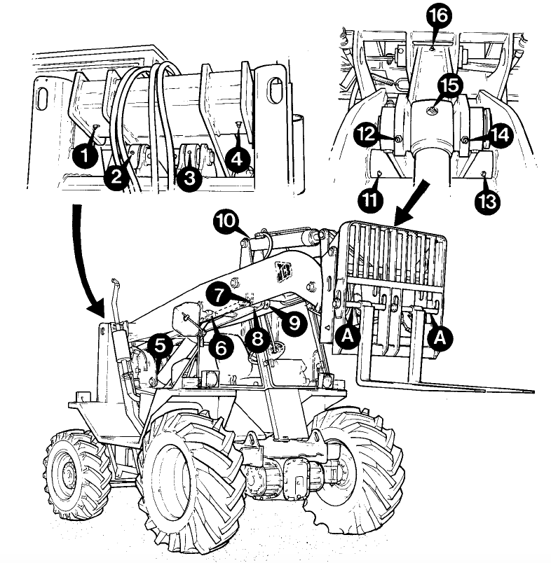
SELECTORS
Dismantling and Assembly
When Dismantling 7′ When removing selector fork 3 from rail, care to be taken not to 1 loose ball 4 and spring 5.
…