INSTANT DOWNLOAD
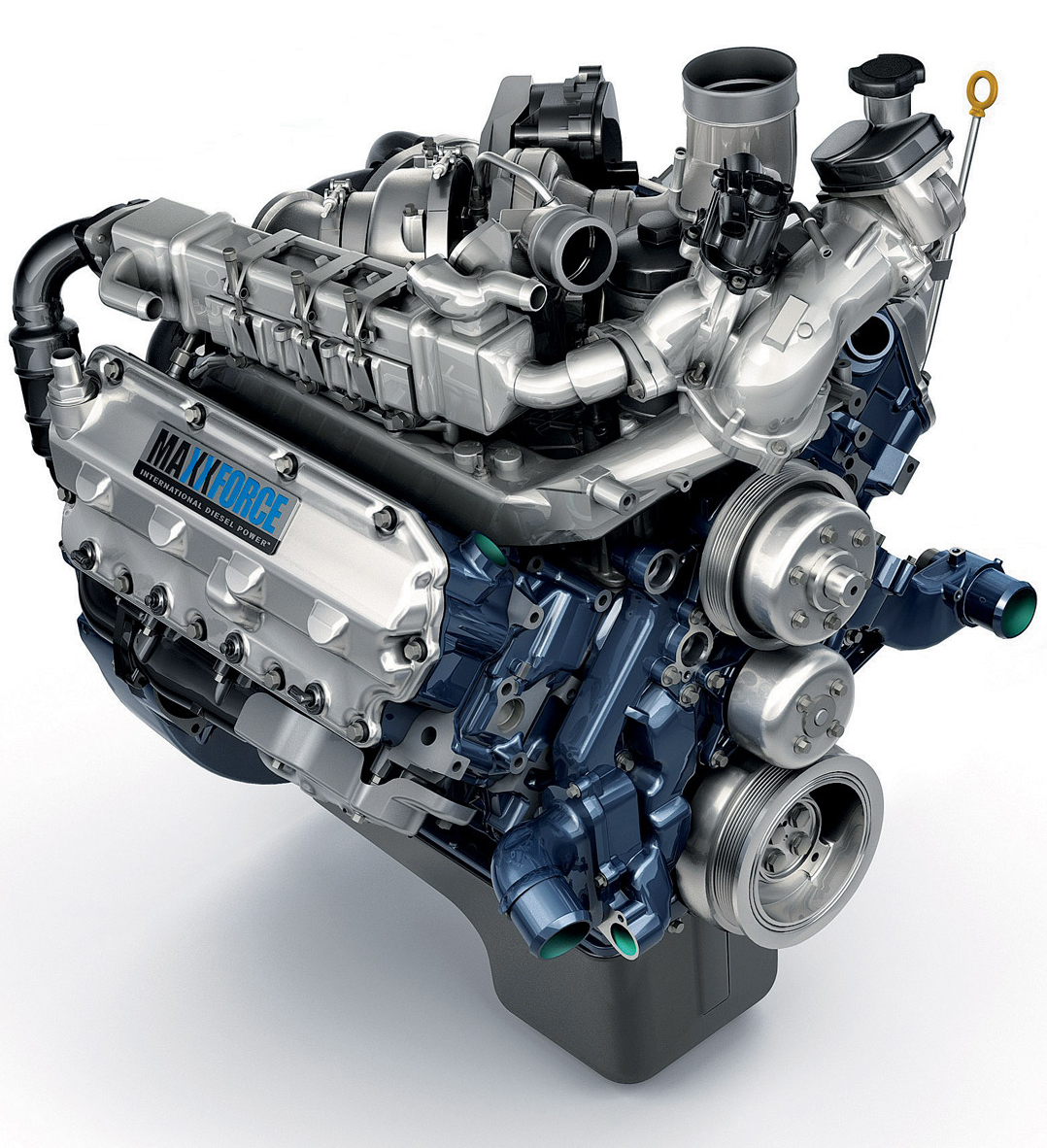
Complete digital official shop manual contains service, maintenance, and troubleshooting information for the International/Navistar MaxxForce 11, MaxxForce 13, MaxxForce 15 Diesel Engine. Diagnostic and repair procedures are covered in great detail to repair, maintain, rebuild, refurbish or restore your vehicle like a professional mechanic in local service/repair workshop. This cost-effective quality manual is 100% complete and intact as should be without any missing pages. It is the same factory shop manual used by dealers that guaranteed to be fully functional to save your precious time.
This manual for MF11, MF13, MF15 Diesel Engine is divided into different sections. Each section covers a specific component or system and, in addition to the standard service procedures, includes disassembling, inspecting, and assembling instructions. A table of contents is placed at the beginning of each section. Pages are easily found by category, and each page is expandable for great detail. It is in the cross-platform PDF document format so that it works like a charm on all kinds of devices. You do not need to be skilled with a computer to use the manual.
FILELIST:
EGES-415 – MaxxForce 11 and 13 Service Manual
EGES-415-2 – MaxxForce 11 and 13 Engine Service Manual (2009-05)
EGES-420 – MaxxForce 11 and 13 Engine Diagnostic_Troubleshooting manual
EGES-420-2 – MaxxForce 11 and 13 Engine Diagnostic_Troubleshooting manual
0000001682 – MaxxForce 11 and 13 Engine Service Manual (2013-02).pdf
0000001682 – MaxxForce 11 and 13 Engine Service Manual (2014-03).pdf
0000001682 – MaxxForce 11 and 13 Engine Service Manual (2015-06).pdf
0000001741 – MaxxForce 11 and 13 Engine Diagnostic Manual (2013-02).pdf
0000001741 – MaxxForce 11 and 13 Engine Diagnostic Manual (2014-04).pdf
0000001741 – MaxxForce 11 and 13 Engine Diagnostic Manual (2015-07).pdf
0000001742 – Manuel de Diagnostique Les moteurs MaxxForce 11 et 13 2010 (2013-02).pdf
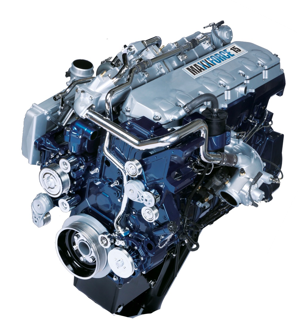
0000001746 – Engine Service Manual MaxxForce 15L Diesel Engine.pdf
0000001746 – MaxxForce 15L Diesel Engine Service Manual.pdf
0000001921 – Manuel de Reparation Moteurs MaxxForce 11 et 13.pdf
0000001922 – Manual de Servicio Del Motor MaxxForce 11 y 13.pdf
0000002861 – 2013 HD-OBD Diagnostic Reference Manual.pdf
0000002941 – Electronic Control System Diagnostics Maxxforce 11 and 13 Beginning with 2010 Model Year.pdf
0000003081 – Aftertreatment Symptom-Based Diagnostic and Inspection Manual MaxxForce DT, 9, 10, 11, 13 and 15 (EPA 10).pdf
0000003941 – Manual de Diagnóstico Motor MaxxForce 11 y 13.pdf
1171898R5 – Engine Operation and Maintenance Manual MaxxForce 11 and 13 Diesel Engines.pdf
1172042R1 – Engine Operation and Maintenance Manual MaxxForce 15 Diesel Engine.pdf
EGED-430-2 – Engine Wiring Diagram Maxxforce 11 and 13 2008 Model Year.pdf
EGED-435 – Maxxforc ETM 11 and 13 2008 Model Year Signal Values (All values with the breakout box installed on the ECM, EIM, ACM, and harness).pdf
EGED-475-3 – Hard Start and No Start Diagnostics MaxxForce 11 & 13 Beginning with 2010 Model Year.pdf
EGED-520-2 – Hard Start and No Start Diagnostics MaxxForce 15 Beginning with 2011 Model Year.pdf
EGED-525-1 – Engine Wiring Diagram Form Maxxforce 15 Beginning with 2011 Model Year.pdf
EGED-530-3 – Performance Diagnostics MaxxForce 11 & 13 EPA 2010.pdf
EGED-535-2 – Performance Diagnostics MaxxForce 15 Beginning with 2011 Model Year.pdf
EGES-415-2 – MaxxForce 11 and 13 Engine Service Manual (2011).pdf
EGES-465-2 – MaxxForce 11 and 13 Engine Service Manual (2011).pdf
EGES-470-1 – MaxxForce 11 and 13 Engine Diagnostic_Troubleshooting Manual (2011).pdf
EGES-470-1 – MaxxForce 11 and 13 Engine Electronic Control Systems Diagnostics.pdf
EGES-510-2 – MaxxForce 15 Diesel Engine Service Manual Model Year 2011 and Up.pdf
EGES-511 – Manuel d’entretien Et De Réparation MaxxForce 15 Moteur diesel Année modèle 2011 et plus.pdf
EGES-512 – Manual de Servicio MaxxForce 15 Motor Diesel Modelo del año 2011 y más recientes.pdf
EGES-515 – MaxxForce 15 Engine Electronic Control Systems Diagnostics.pdf
EGES-515-1 – MaxxForce 15 Engine Diagnostic_Troubleshooting Manual.pdf
Maxxforce 11 & Maxxforce 13 Model Year 2009 Features, Descriptions, & Unique Repair Procedures.pdf
…
EXCERPT:
TURBOCHARGERS
Turbocharger Oil Return and Oil Supply Tubes
Overview
This section describes removal of turbocharger oil supply tubes after turbocharger oil supply tube retrofit.
If configuration does not match this section see TSI in Appendix D .
1. Remove air intake and pipe, if not already done.
2. Remove CAC pipe from high-pressure charge air cooler and high-pressure turbocharger outlet elbow, if not already done.
3. Remove high-pressure turbocharger outlet elbow from high-pressure turbocharger, if not already done.
4. Remove air inlet duct from low-pressure turbocharger, if not already done.
5. Loosen LP turbocharger oil return tube fitting nut from HP turbocharger oil return tube.
6. Remove four M8 x 20 bolts and disconnect HP oil return tube from HP and LP turbocharger and LP oil return tube.
7. Remove and discard two turbocharger oil drain gaskets.
8. Remove and discard bonded seal washer between HP and LP turbocharger oil return tubes.
9. Remove LP turbocharger oil return tube from crankcase and discard 24.7 x 32 seal ring.
…
ENGINE SERVICE MANUAL
MaxxForce 15L Diesel Engine
Cleaning, Inspection, and Testing
WARNING: To prevent personal injury or death, wear safety glasses with side shields.
Limit compressed air pressure to 207 kPa (30 psi).
Exhaust Gas Recirculation (EGR) System
Components
NOTE: To maintain and ensure peak engine
performance, it is critical to do the following cleaning and inspecting procedures.
1. Clean all mating surfaces to ensure proper gasket sealing.
2. Inspect all EGR system components for cracks, leaks, and damage. Replace damaged parts as required.
EGR Valve Assembly
1. Inspect EGR valve to make sure it is fully closed. Replace the valve if necessary.
2. Inspect electrical connections on EGR valve assembly and engine harness connector for corrosion or damage. Replace if necessary.
3. Clean all mating surfaces to ensure proper gasket sealing.
NOTE: Refer to MaxxForce® 15 Engine Diagnostic Manual for functional check of EGR valve assembly