Posted on

Caterpillar 3406E & 3456 Engine Workshop Repair & Service Manual


Download Link

INSTANT DOWNLOAD


Complete digital official shop manual contains service, maintenance, and troubleshooting information for the Caterpillar 3406, 3406B, 3406C, 3406E Engine. Diagnostic and repair procedures are covered in great detail to repair, maintain, rebuild, refurbish or restore your engine like a professional mechanic in local service/repair workshop. This cost-effective quality manual is 100% complete and intact as should be without any missing pages. It is the same factory shop manual used by dealers that guaranteed to be fully functional to save your precious time.

This manual for Caterpillar 3406, 3406B, 3406C, 3406E Engine is divided into different sections. Each section covers a specific component or system and, in addition to the standard service procedures, includes disassembling, inspecting, and assembling instructions. A table of contents is placed at the beginning of each section. Pages are easily found by category, and each page is expandable for great detail. It is in the cross-platform PDF document format so that it works like a charm on all kinds of devices. You do not need to be skilled with a computer to use the manual.

ENGINE – GENERATOR SET
Model Prefix
3406 GEN SET ENGINE 75Z
3406B GEN SET ENGINE 2RJ
3406B GEN SET ENGINE 2WB
3406B GEN SET ENGINE 4JK
3406B GEN SET ENGINE 4PM
3406B GEN SET ENGINE 4RG
3406B GEN SET ENGINE 6TG
3406B GEN SET ENGINE 9PL
3406C GEN SET ENGINE 1LS
3406C GEN SET ENGINE 4JK
3406C GEN SET ENGINE 4RG
3406C GEN SET ENGINE 4ZR
3406C GEN SET ENGINE 8FS
3406C GENERATOR SET 9ES
3406C GENERATOR SET C2G
3406C GENERATOR SET C2Y
3406C GENERATOR SET C5G
3406C GENERATOR SET C8G
3406C GENERATOR SET KPS
3406C GENERATOR SET LRX
3406C GENERATOR SET NKM
3406C GENERATOR SET ZKC
3406E GEN SET ENGINE 9NN
3406E GENERATOR SET 8AZ

ENGINE – INDUSTRIAL
Model Prefix
3406 INDUSTRIAL ENGINE 90U
3406 INDUSTRIAL ENGINE 9HB
3406B INDUSTRIAL ENGINE 6TB
3406B INDUSTRIAL ENGINE WJA
3406C INDUSTRIAL ENGINE 3ER
3406C INDUSTRIAL ENGINE 4GW
3406C INDUSTRIAL ENGINE 5H9
3406C INDUSTRIAL ENGINE 7T2
3406C REMAN ENGINE 2MZ
3406E INDUSTRIAL ENGINE 6BR

ENGINE – MACHINE
Model Prefix
3406 ENGINE – MACHINE 11N
3406 ENGINE – MACHINE 41Z
3406 ENGINE – MACHINE 70V
3406 ENGINE – MACHINE 81Y
3406 ENGINE – MACHINE 9AP
3406 ENGINE – MACHINE A5Y
3406 ENGINE – MACHINE BMS
3406B ENGINE – MACHINE 11N
3406B ENGINE – MACHINE 6TB
3406C ENGINE – MACHINE 11N
3406C ENGINE – MACHINE 41Z
3406C ENGINE – MACHINE A5N
3406C ENGINE – MACHINE A5Y
3406C ENGINE – MACHINE TXC
3406E ENGINE – MACHINE 9AP
3406E ENGINE – MACHINE BET
3406E ENGINE – MACHINE BKN

ENGINE – TRUCK
Model Prefix
3406 REMAN ENGINE 8SB
3406 TRUCK ENGINE 8SB
3406 TRUCK ENGINE 92U
3406B REMAN ENGINE 7XC
3406B TRUCK ENGINE 2EK
3406B TRUCK ENGINE 3ZJ
3406B TRUCK ENGINE 4CK
3406B TRUCK ENGINE 4MG
3406B TRUCK ENGINE 5KJ
3406B TRUCK ENGINE 5YG
3406B TRUCK ENGINE 7FB
3406B TRUCK ENGINE 8TC
3406C TRUCK ENGINE 3ZJ
3406C TRUCK ENGINE 4CK
3406C TRUCK ENGINE 5KJ
3406C TRUCK ENGINE 8PN
3406E REMAN ENGINE 4AS
3406E TRUCK ENGINE 1LW
3406E TRUCK ENGINE 1MM
3406E TRUCK ENGINE 2WS
3406E TRUCK ENGINE 5DS
3406E TRUCK ENGINE 5EK
3406E TRUCK ENGINE 6TS

MARINE PRODUCTS
Model Prefix
3406 MARINE ENGINE 91U
3406B MARINE ENGINE 4TB
3406C GEN SET ENGINE 2AM
3406C GEN SET ENGINE 4BM
3406C GENERATOR SET PFH
3406C MARINE ENGINE 1SS
3406C MARINE ENGINE 4T7
3406E MARINE ENGINE 9WR

MANUAL LIST:
bonus_material
RENR1273 – Systems Operation (3406E Truck Engine)
RENR1273 – Testing & Adjusting (3406E Truck Engine)
RENR2237 – Schematic (C-10_C-12_3406E_C-15_C-16 On-Highway Engine Electrical System)
SEBU6758 – Operation & Maintenance Manual (3176B_C-10_C-12_3406E Truck Engine)
SEBU6959 – Operation & Maintenance Manual (3406E & 3456 Industrial Engines)
SEBU7186 – Operation & Maintenance Manual (3406E_C-10_C-12_C-15_C-16 Truck Engine)
SENR1066 – Specifications (3406E & 3456 Industrial Engines)
SENR1067 – Systems Operation (3406E & 3456 Industrial Engines)
SENR1067 – Testing & Adjusting (3406E & 3456 Industrial Engines)
SENR1068 – Disassembly & Assembly (3406E & 3456 Industrial Engine)
SENR1072 – Schematic (3176C, 3196, 3406E & 3456 Industrial Engines)
SENR1073 – Troubleshooting (3176C, 3406E & 3456 Industrial Engines)
SENR5017 – Systems Operation (3406E Truck Engine)
SENR5017 – Testing & Adjusting (3406E Truck Engine)
SENR5577 – Specifications (3406E Truck Engine)
SENR6421 – Disassembly & Assembly (3406E On-Highway Engine)
RENR2238 – Toubleshooting (3406E_C-10_C-12_C-15_C-16_C-18 Truck Engine).pdf
SEBU5595 – Maintenance Intervals Operation and Maintenance Manual Excerpt (3406E Truck Engines).pdf
SEBU7186 – Maintenance Intervals (3406E,C-10,C-12,C-15,C-16 On-Highway Engine).pdf
SENR5016 – Disassembly and Assembly (3406E On-Highway Engine).pdf
SESV1712 – 3406E Engine Controls Electronic Unit Injection (Eui) Technical Presentation.pdf
SESV1712 – Technical Presentation (3406E Engine Controls Electronic Unit Injection (EUI)).pdf

EXCERPT:

Disassembly and Assembly
3406E & 3056 INDUSTRIAL ENGINE Media Number -SENR1068-03 Publication Date -01/11/2004 Date Updated -20/12/2004

Fuel Manifold
SMCS – 1702-010

Remove & Install Fuel Manifold
Fluid Spillage Containment

Care must be taken to ensure that fluids are contained during performance of inspection, maintenance, testing, adjusting and repair of the machine. Be prepared to collect the fluid with suitable containers before opening any compartment or disassembling any component containing fluids. Refer to “Tools And Shop Products Guide”, NENG2500 for tools and supplies suitable to collect and contain fluids in Caterpillar machines. Dispose of fluids according to local regulations and mandates.

View Image

View Image

1. Put marks on the fuel lines connected to fuel manifold (1) for purposes of identification. Disconnect the fuel lines to fuel manifold (1).

2. Remove the support clip holding wire (2) to the cylinder block. Disconnect wire (2) at the connector.

NOTICE

Upon installation, the connector must pull into the receptacle using the Allen screws. A clip holds the Allen screws into the connector. Removing the screws will damage the seals.

3. Remove bolts (3) holding fuel manifold (1) to the cylinder block. Remove fuel manifold (1).
4. Install fuel manifold (1) in the reverse order of removal.

Posted on

Caterpillar 3406C Diesel Engines Factory Service & Shop Manual


Download Link

INSTANT DOWNLOAD


Complete workshop & service manual with electrical wiring diagrams for Caterpillar 3406C Diesel Engines. It’s the same service manual used by dealers that guaranteed to be fully functional and intact without any missing page.

This Caterpillar 3406C Diesel Engines service & repair manual (including maintenance, overhaul, disassembling & assembling, adjustment, tune-up, operation, inspecting, diagnostic & troubleshooting…) is divided into different sections. Each section covers a specific component or system with detailed illustrations. A table of contents is placed at the beginning of each section. Pages are easily found by category, and each page is expandable for great detail. The printer-ready PDF documents work like a charm on all kinds of devices.

MANUAL LIST:
RENR1377 – Systems Operation (Electric Protection System Energize-To-Run for Generator Set, Industrial & Marine Diesel Engines)
RENR1377 – Testing & Adjusting (Electric Protection System Energize-To-Run for Generator Set, Industrial & Marine Diesel Engines)
SEGV3008 – Systems Operation (Fundamentals Electrical System for All Caterpillar Products)
SENR3130 – Torque Specifications
SENR3981 – Schematic – Fluid Power & Electrical Graphic Symbols
SENR4024 – Specifications (Industrial & Marine Engine Attachments)
SENR6521 – Troubleshooting (3406C Diesel Truck Engine)
SENR6523 – Specifications (3406C Industrial & Marine Engines)
SENR6525 – Disassembly & Assembly (3406C Industrial & Marine Engines)
SENR6526 – Disassembly and Assembly (3406C Industrial & Marine Engines)
SENR6527 – Specifications (3406C Industrial & Marine Engine Attachments)
SENR6546 – Specifications (3406C Diesel Truck Engine)
SENR6548 – Disassembly & Assembly (3406C Diesel Truck Engine)
SENR7508 – Disassembly & Assembly (30SI Series and 34SI Series Alternator)
SENR7508 – Systems Operation (30SI Series and 34SI Series Alternator)
SENR7508 – Testing & Adjusting (30SI Series and 34SI Series Alternator)
SENR7594 – General Service Information (Midland Air Compressors)
UENR3262 – Disassembly & Assembly – Seal Installation
SEBF9050 – Applied Failure Analysis – Engine Valve Failure Modes{1100, 1105}.pdf
SEBU6875 – Owner’s Manual (Caterpillar Driver Information Display).pdf
SENR2995 – Product Safety.pdf
SENR3130 – Specifications (Torque Specifications for All Caterpillar Products).pdf
SENR6524 – Systems Operation (3406C Industrial & Marine Engines).pdf
SENR6524 – Testing & Adjusting (3406C Industrial & Marine Engines).pdf
SENR6528 – Systems Operation (3406C Industrial & Marine Engine Attachments).pdf
SENR6528 – Testing & Adjusting (3406C Industrial & Marine Engine Attachments).pdf
SENR6547 – Systems Operation (3406C Diesel Truck Engine).pdf
SENR6547 – Testing & Adjusting (3406C Diesel Truck Engine).pdf
SENR7508 – Specifications (30SI Series and 34SI Series Alternator).pdf

EXCERPT:
BrakeSaver Troubleshooting
There are two operation checks that are fast and need no special equipment. One check is the Pull-Down RPM Check to see if the BrakeSaver can give full braking force. The other check is the Klunk Check to see if the valve spool in the BrakeSaver control valve has free movement. These two checks give an approximate indication that the BrakeSaver has the correct operation.
Pull-Down RPM Check
NOTE: The engine must give rated horsepower for this test to have accuracy.
1. Actuate the brakes, put the transmission in NEUTRAL and operate the engine at high idle rpm (accelerator pedal all the way down).
2. Make a record of the engine rpm.
3. Put the BrakeSaver control to the full ON position.
4. Make a record of the engine rpm with the BrakeSaver full on.

Posted on

Caterpillar 3406 & 3406B Engines Factory Service & Shop Manual


Download Link

INSTANT DOWNLOAD


Complete workshop & service manual with electrical wiring diagrams for Caterpillar 3406 & 3406B Disel Engines. It’s the same service manual used by dealers that guaranteed to be fully functional and intact without any missing page.

This Caterpillar 3406 & 3406B Engines service & repair manual (including maintenance, overhaul, disassembling & assembling, adjustment, tune-up, operation, inspecting, diagnostic & troubleshooting…) is divided into different sections. Each section covers a specific component or system with detailed illustrations. A table of contents is placed at the beginning of each section. Pages are easily found by category, and each page is expandable for great detail. The printer-ready PDF documents work like a charm on all kinds of devices.

MANUAL LIST:
SEBR0544 – Disassembly & Assembly (3406B Diesel Truck Engine)
SEBR0544 – Specifications (3406B Diesel Truck Engine)
SEBR0544 – Troubleshooting (3406B Diesel Truck Engine)
SENR1012 – Troubleshooting (3176B_C-10_C-12_3406E Truck Engine Basic Electronic Trou)
SENR2536 – Specifications (3406 & 3406B Generator Set Engine)
SENR3479 – Troubleshooting (3406B (PEEC) Programmable Electronic Engine Controls)
SENR3484 – Specifications (3406 (PEEC) Diesel Truck Engine)
SENR3486 – Electrical System (3406 (PEEC) Diesel Truck Engine)
SENR3487 – Disassembly & Assembly (3406B (PEEC) Diesel Truck Engine)
SENR3920 – Disassembly & Assembly (3406 & 3406B Generator Set Engine)
SENR4022 – Specifications (3406B Industrial & Marine Engines)
SENR4026 – Disassembly & Assembly (3406B Industrial & Marine Engines)
SENR5582 – Troubleshooting (3176B_C-10_C-12_3406E Truck Engines)
UENR5429 – Schematic (3406B & 3406C Fire Pump Engine Electrical System)
SEBR0544 – Systems Operation (3406B Diesel Truck Engine).pdf
SEBR0544 – Testing & Adjusting (3406B Diesel Truck Engine).pdf
SENR2537 – Systems Operations (3406 & 3406B Generator Set Engine).pdf
SENR2537 – Testing & Adjusting (3406 & 3406B Generator Set Engine).pdf
SENR3485 – Systems Operation (3406B (PEEC) Diesel TR).pdf
SENR3485 – Testing & Adjusting (3406B (PEEC) Diesel TR).pdf
SENR4023 – Systems Operation (3406B Industrial & Marine Engines).pdf
SENR4023 – Testing & Adjusting (3406B Industrial & Marine Engines).pdf
SENR4025 – Systems Operation (3406B Industrial & Marine Engine Attachments).pdf
SENR4025 – Testing & Adjusting (3406B Industrial & Marine Engine Attachments).pdf
SENR5574 – Schematic (3176B_C-10_C-12_3406E Truck Engines).pdf
RENR1377 – Systems Operation (Electric Protection System Energize-To-Run for Generator Set, Industrial & Marine Diesel Engines)
RENR1377 – Testing & Adjusting (Electric Protection System Energize-To-Run for Generator Set, Industrial & Marine Diesel Engines)
SEGV3008 – Systems Operation (Fundamentals Electrical System for All Caterpillar Products)
SENR3130 – Torque Specifications
SENR3981 – Schematic – Fluid Power & Electrical Graphic Symbols
SENR4024 – Specifications (Industrial & Marine Engine Attachments)
SENR6521 – Troubleshooting (3406C Diesel Truck Engine)
SENR6523 – Specifications (3406C Industrial & Marine Engines)
SENR6525 – Disassembly & Assembly (3406C Industrial & Marine Engines)
SENR6526 – Disassembly and Assembly (3406C Industrial & Marine Engines)
SENR6527 – Specifications (3406C Industrial & Marine Engine Attachments)
SENR6546 – Specifications (3406C Diesel Truck Engine)
SENR6548 – Disassembly & Assembly (3406C Diesel Truck Engine)
SENR7508 – Disassembly & Assembly (30SI Series and 34SI Series Alternator)
SENR7508 – Systems Operation (30SI Series and 34SI Series Alternator)
SENR7508 – Testing & Adjusting (30SI Series and 34SI Series Alternator)
SENR7594 – General Service Information (Midland Air Compressors)
UENR3262 – Disassembly & Assembly – Seal Installation
SEBF9050 – Applied Failure Analysis – Engine Valve Failure Modes{1100, 1105}.pdf
SEBU6875 – Owner’s Manual (Caterpillar Driver Information Display).pdf
SENR2995 – Product Safety.pdf
SENR3130 – Specifications (Torque Specifications for All Caterpillar Products).pdf
SENR6524 – Systems Operation (3406C Industrial & Marine Engines).pdf
SENR6524 – Testing & Adjusting (3406C Industrial & Marine Engines).pdf
SENR6528 – Systems Operation (3406C Industrial & Marine Engine Attachments).pdf
SENR6528 – Testing & Adjusting (3406C Industrial & Marine Engine Attachments).pdf
SENR6547 – Systems Operation (3406C Diesel Truck Engine).pdf
SENR6547 – Testing & Adjusting (3406C Diesel Truck Engine).pdf
SENR7508 – Specifications (30SI Series and 34SI Series Alternator).pdf

EXCERPT:
FUEL SYSTEM SCHEMATIC
1. Fuel injection nozzle. 2. Fuel injection lines. 3. Fuel return line. 4. Constant bleed orifice (part of the elbow). 5. Fuel injection pump housing. 6. Fuel priming pump. 7. Check valves. 8. Fuel transfer pump. 9. Fuel tank. 10. Primary fuel filter. 11. Secondary fuel filter. Fuel is pulled from fuel tank (9) through primary fuel filter (10) by fuel transfer pump (8). From the fuel transfer pump the fuel is pushed through secondary fuel filter (11) and to the fuel manifold in fuel injection pump housing (5). Fuel pressure in the fuel manifold is determined by the fuel transfer pump spring. A constant bleed orifice is in the fuel return line elbow. Constant bleed orifice (4) lets a constant flow of fuel go through fuel return line (3) back to fuel tank (9). This helps keep the fuel cool and free of air. The individual fuel injection pumps get fuel from the fuel manifold and push fuel at a very high pressure through fuel lines (2) to fuel injection nozzles (1). Each fuel injection nozzle has very small holes in the tip that change the flow of fuel to a very fine spray that gives good fuel combustion in the cylinder.

Posted on

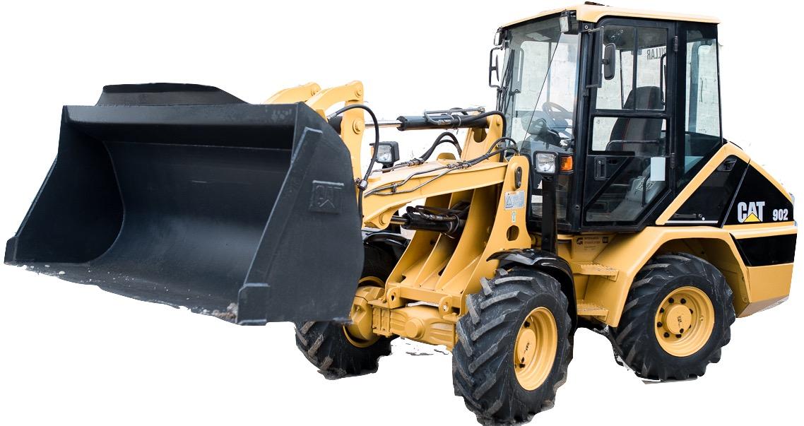
Caterpillar 902 and 906 Compact Wheel Loaders Factory Service & Shop Manual


Download Link

INSTANT DOWNLOAD


Complete workshop & service manual with electrical wiring diagrams for Caterpillar 902 and 906 Compact Wheel Loaders. It’s the same service manual used by dealers that guaranteed to be fully functional and intact without any missing page.

This Caterpillar 902 and 906 Compact Wheel Loaders service & repair manual (including maintenance, overhaul, disassembling & assembling, adjustment, tune-up, operation, inspecting, diagnostic & troubleshooting…) is divided into different sections. Each section covers a specific component or system with detailed illustrations. A table of contents is placed at the beginning of each section. Pages are easily found by category, and each page is expandable for great detail. The printer-ready PDF documents work like a charm on all kinds of devices.

MANUAL LIST:
RENR2824 – Testing & Adjusting (902 and 906 Compact Wheel Loaders Power Train System)
RENR4805 – Schematic (902, 906, & 908 Compact Wheel Loader Electrical System)
RENR4860 – Schematic (902, 906 & 908 Compact Wheel Loader Electrical System)
RENR9860 – Schematic (902, 906 & 908 Compact Wheel Loader Electrical System)
SENR1283 – Disassembly and Assembly (902 and 906 Wheel Loaders Power Train)
SENR1284 – Specifications (902 and 906 Wheel Loaders)
SENR1285 – Disassembly and Assembly (902 and 906 Compact Wheel Loaders Engine Supplement)
SENR1286 – Systems Operation (902 and 906 Compact Wheel Loaders Power Train System)
SENR1287 – Specifications (902 and 906 Compact Wheel Loaders Steering System)
SENR1288 – Systems Operation (902 and 906 Compact Wheel Loaders Steering System)
SENR1288 – Testing & Adjusting (902 and 906 Compact Wheel Loaders Steering System)
SENR1289 – Specifications (902 and 906 Compact Wheel Loaders Braking System)
SENR1290 – Systems Operation (902 and 906 Compact Wheel Loaders Braking System)
SENR1290 – Testing & Adjusting (902 and 906 Compact Wheel Loaders Braking System)
SENR1291 – Specifications (902 and 906 Compact Wheel Loaders Hydraulic System)
SENR1292 – Systems Operation (902 and 906 Compact Wheel Loaders Hydraulic System)
SENR1292 – Testing and Adjusting (902 and 906 Compact Wheel Loaders Hydraulic System)
SENR1293 – Disassembly and Assembly (902 and 906 Compact Wheel Loaders Machine Systems)
SENR1294 – Schematic (902, 906 and 908 Compact Wheel Loader Hydraulic System)
SENR1295 – Schematic (902 and 906 Compact Wheel Loader Electrical System)

EXCERPT:
Start By:
Release the hydraulic pressure. Refer to Disassembly and Assembly, “Hydraulic System Pressure – Release”.
A.
Remove the quick coupler. Refer to Disassembly and Assembly, “Quick Coupler – Remove and Install”.
B.
Remove tilt cylinder. Refer to Disassembly and Assembly, “Tilt Cylinder – Remove and Install”.
C.
Remove the tilt link. Refer to Disassembly and Assembly, “T D. ilt Link – Remove and Install”.
E. Remove the tilt lever. Refer to Disassembly and Assembly, “Tilt Lever – Remove and Install”.
Remove the lift cylinder. Refer to Disassembly and Assembly, “Lift Cylinder – Remove and Install”.

Posted on

Caterpillar 3176C & 3196 Engines Factory Service & Shop Manual


Download Link

INSTANT DOWNLOAD


Complete workshop & service manual with electrical wiring diagrams for Caterpillar 3176C & 3196 Engines. It’s the same service manual used by dealers that guaranteed to be fully functional and intact without any missing page.

This Caterpillar 3176C & 3196 Engines service & repair manual (including maintenance, overhaul, disassembling & assembling, adjustment, tune-up, operation, inspecting, diagnostic & troubleshooting…) is divided into different sections. Each section covers a specific component or system with detailed illustrations. A table of contents is placed at the beginning of each section. Pages are easily found by category, and each page is expandable for great detail. The printer-ready PDF documents work like a charm on all kinds of devices.

MANUAL LIST:
RENR1232 – Testing & Adjusting (3176C & 3196 Marine Engines).pdf
RENR1231 – Specifications (3176C and 3196 Marine Engines)
RENR1233 – Disassembly and Assembly (3176C and 3196 Marine Engines)
SENR1170 – Troubleshooting (3176C, 3196 & 3406E Marine Engines)
SENR1171 – Schematic (3176C & 3196 Marine Engines Electrical System)
RENR1232 – Systems Operation (3176C & 3196 Marine Engines).pdf

EXCERPT:
2. Raise the temperature of bearings (3) .
3. Place bearings (3) in the original location on gear and shaft (2) .
4. Use Tooling (B) in order to install retaining ring (4) into accessory drive housing (5) .
5. Install gear and shaft (2) with bearings (3) into accessory drive housing (5) .
6. Install bolts (1) .
End By: Install the accessory drive. Refer to Disassembly and Assembly, “Accessory Drive – Install”.