Posted on

Komatsu Dump Truck 860E-1AC, 860E-1K, 860E-1KT Workshop Repair & Service Manual

Komatsu 860E-1K, 860E-1KT

MKMTS860EOPES.PDF
Price: $29.99 USD

Complete digital official shop manual contains service, maintenance, and troubleshooting information for the Komatsu Dump Truck 860E-1AC, 860E-1K, 860E-1KT. Diagnostic and repair procedures are covered in great detail to repair, maintain, rebuild, refurbish or restore your trucks like a professional mechanic in local service/repair workshop. This cost-effective quality manual is 100% complete and intact as should be without any missing pages. It is the same factory shop manual used by dealers that guaranteed to be fully functional to save your precious time.

This manual for Komatsu Dump Truck 860E-1AC, 860E-1K, 860E-1KT is divided into different sections. Each section covers a specific component or system and, in addition to the standard service procedures, includes disassembling, inspecting, and assembling instructions. A table of contents is placed at the beginning of each section. Pages are easily found by category, and each page is expandable for great detail. It is in the cross-platform PDF document format so that it works like a charm on all kinds of devices. You do not need to be skilled with a computer to use the manual.

CEAM019501 – Dump Truck 860E-1KT Operation & Maintenance Manual.pdf
CEAM021602 – Dump Truck 860E-1KT Operation & Maintenance Manual.pdf
CEAM022401 – Dump Truck 860E-1KT Operation & Maintenance Manual.pdf
CEAM024703 – Dump Truck 860E-1KT Operation & Maintenance Manual.pdf
CEAM026003 – Dump Truck 860E-1KT Operation & Maintenance Manual.pdf
CEAW005702 – Dump Truck 860E-1KT Field Assembly Manual.pdf
CEAW007201 – Dump Truck 860E Field Assembly Manual Manual.pdf
CEBM021403 – Dump Truck 860E-1KT Shop Manual.pdf
CEBM022005 – Dump Truck 860E-1KT Shop Manual.pdf
CEBM024202 – Dump Truck 860E-1K Shop Manual.pdf
CEBM024800 – Dump Truck 860E-1AC Shop Manual.pdf
CEBM025801 – Dump Truck 860E-1KT Shop Manual.pdf

EXCERPT:

30 Testing and adjusting CEN30021-02
Notes on the display of connectors
• Work window (Work)
• Connectors displayed in terms of physical units
• Displayed online (i.e., if the communications link is overloaded, values may be “lost”)
• The display can also be recorded (see Set Record)
• Same sequence as for bar graphics display
– Bar graphics (Bars)
• Display related to “100% value” of the connector
• Displayed online (i.e., if the communications link is overloaded, values may be “lost”)
• Bar legend:
– Name of the connector or signal
– Unit of the connector displayed
– “100% value” in physical units
• Display of positive values with solid bars
• Display of negative values with shaded bars
– Line graphics (Lines)
• Display can be altered by means of Graphic commands (Position, Time/Div, Unit/Div)
• Dashes at the left-hand side of the window denote the zero lines
• Time shown top right denotes the time before / after the recording is stopped:
– – Time before recording stopped
-+ Time after recording stopped
• Designations of the connectors and the scale in which they are displayed are shown at the right-hand edge of the window; the time scale is displayed bottom right.
• Horizontal and vertical scroll bars and sliders can only be operated with the mouse.
• After recording has been terminated (Observer), the data must be transferred
immediately; during the transfer time, the Customer Monitor changes the mouse pointer into an hourglass.
• Values of the time denoted by the cursor are displayed in physical units on the right next to the connector or signal name.
• The cursor is moved by means of:
– [Right arrow] or [Left arrow] for slow movements
– [Shift] or [Ctrl] + [Right arrow] or [Left arrow] for rapid movements
If the graphics window has not yet been opened when the Observer is started, the Customer Monitor opens the work and graphics windows automatically.
The operator, however, can organize the windows as required; they are then no longer altered.
“Applic. Buffer”
This function is used to set software values in the memory. Changing a connector value in the memory will cause SIBAS® to use the change each time it is started up.
Options
1) /Edit->CNN: Adds of changes the specified connector in the buffer
2) /Del -> CNN: Deletes the specified connector from the buffer
3) /Release: Saves the buffer to the CPU card’s memory
4) /Clear: Erases all buffer values
Selecting “/Edit” but not entering a connector will display the first value in the buffer. Pressing the down arrow will show consecutive values and then repeat starting with the first value. Each value is indexed and a total of 32 can be stored in the buffer at one time.

Posted on

Komatsu Dump Truck 830E, 830E-AC, 830E-1AC Factory Service & Shop Manual

Pages from CEBM014900 – Dump Truck 830E Shop Manual

MKMTS830EOPES.PDF
Price: $29.99 USD

Complete workshop & service manual with electrical wiring diagrams for Komatsu Dump Truck 830E, 830E-AC, 830E-1AC. It’s the same service manual used by dealers that guaranteed to be fully functional and intact without any missing page.

This Komatsu Dump Truck 830E, 830E-AC, 830E-1AC service & repair manual (including maintenance, overhaul, disassembling & assembling, adjustment, tune-up, operation, inspecting, diagnostic & troubleshooting…) is divided into different sections. Each section covers a specific component or system with detailed illustrations. A table of contents is placed at the beginning of each section. Pages are easily found by category, and each page is expandable for great detail. The printer-ready PDF documents work like a charm on all kinds of devices.

FILELIST (1.3G PDF):
CEAM006200 – Dump Truck 830E Operation & Maintenance Manual.pdf
CEAM010400 – Dump Truck 830E Operation & Maintenance Manual.pdf
CEAM010600 – Dump Truck 830E Operation & Maintenance Manual.pdf
CEAM011500 – Dump Truck 830E Operation & Maintenance Manual.pdf
CEAM013204 – Dump Truck 830E Operation & Maintenance Manual.pdf
CEAM013400 – Dump Truck 830E Operation & Maintenance Manual.pdf
CEAM015001 – Dump Truck 830E Operation & Maintenance Manual.pdf
CEAM015201 – Dump Truck 830E Operation & Maintenance Manual.pdf
CEAM016303 – Dump Truck 830E-AC Operation & Maintenance Manual.pdf
CEAM016800 – Dump Truck 830E Operation & Maintenance Manual.pdf
CEAM018802 – Dump Truck 830E-AC Operation & Maintenance Manual.pdf
CEAM018903 – Dump Truck 830E-1AC Operation & Maintenance Manual.pdf
CEAM019102 – Dump Truck 830E-1AC Operation & Maintenance Manual.pdf
CEAM019302 – Dump Truck 830E-1AC Operation & Maintenance Manual.pdf
CEAM019903 – Dump Truck 830E-1AC Operation & Maintenance Manual.pdf
CEAM020101 – Dump Truck 830E-1AC Operation & Maintenance Manual.pdf
CEAM020801 – Dump Truck 830E-1AC Operation & Maintenance Manual.pdf
CEAM021501 – Dump Truck 830E-1AC Operation & Maintenance Manual.pdf
CEAM022303 – Dump Truck 830E-1AC Operation & Maintenance Manual.pdf
CEAM024100 – Dump Truck 830E-1AC Operation & Maintenance Manual.pdf
CEAM024403 – Dump Truck 830E-1AC Operation & Maintenance Manual.pdf
CEAM025001 – Dump Truck 830E-1AC Operation & Maintenance Manual.pdf
CEAM026901 – Dump Truck 830E-1AC Operation & Maintenance Manual.pdf
CEAM027001 – Dump Truck 830E-1AC Operation & Maintenance Manual.pdf
CEAW004503 – Dump Truck 830E-AC Field Assembly Manual.pdf
CEAW004701 – Dump Truck 830E Field Assembly Manual.pdf
CEAW005100 – Dump Truck 830E-1AC Field Assembly Manual.pdf
CEAW006300 – Dump Truck 830E-1AC Field Assembly Manual.pdf
CEAW006402 – Dump Truck 830E-1AC Field Assembly Manual.pdf
CEAW006700 – Dump Truck 830E-1AC Field Assembly Manual.pdf
CEAW006802 – Dump Truck 830E-1AC Field Assembly Manual.pdf
CEAW006803 – Dump Truck 830E-1AC Field Assembly Manual.pdf
CEBM006300 – Dump Truck 830E Shop Manual.pdf
CEBM006301 – Dump Truck 830E Shop Manual.pdf
CEBM008601 – Dump Truck 830E Shop Manual.pdf
CEBM008900 – Dump Truck 830E Shop Manual.pdf
CEBM010501 – Dump Truck 830E Operation & Maintenance Manual.pdf
CEBM011700 – Dump Truck 830E Shop Manual.pdf
CEBM013200 – Dump Truck 830E Shop Manual.pdf
CEBM013502 – Dump Truck 830E Shop Manual.pdf
CEBM014900 – Dump Truck 830E Shop Manual.pdf
CEBM015101 – Dump Truck 830E Shop Manual.pdf
CEBM016204 – Dump Truck 830E-AC Shop Manual.pdf
CEBM016701 – Dump Truck 830E Shop Manual.pdf
CEBM019202 – Dump Truck 830E-AC Shop Manual.pdf
CEBM019302 – Dump Truck 830E-1AC Shop Manual.pdf
CEBM019602 – Dump Truck 830E-1AC Shop Manual.pdf
CEBM019702 – Dump Truck 830E-1AC Shop Manual.pdf
CEBM020102 – Dump Truck 830E-1AC Shop Manual.pdf
CEBM020403 – Dump Truck 830E-1AC Shop Manual.pdf
CEBM021102 – Dump Truck 830E-1AC Shop Manual.pdf
CEBM021903 – Dump Truck 830E-1AC Shop Manual.pdf
CEBM023501 – Dump Truck 830E-1AC Shop Manual.pdf
CEBM024002 – Dump Truck 830E-1AC Shop Manual.pdf
CEBM027401 – Dump Truck 830E-1AC Shop Manual.pdf
DG594 – Haulpack Truck 830E Shop Manual.pdf
DG621 – Dump Truck 830E Operator Handbook.pdf
DG681 – Dump Truck 830E Shop Manual.pdf
DG723 – Dump Truck 830E Operation & Maintenance Manual.pdf
DG727 – Dump Truck 830E Shop Manual.pdf
DG734 – Dump Truck 830E Shop Manual.pdf
DG753 – Dump Truck 830E Shop Manual.pdf

EXCERPT:
TABLE OF CONTENTS
SUBJECT . . . .SECTION
GENERAL INFORMATION . . . A
STRUCTURES . . . . B
ENGINE, FUEL, COOLING AND AIR CLEANER . . . . C
ELECTRIC SYSTEM (24 VDC. NON-PROPULSION) . . . . D
ELECTRIC PROPULSION AND CONTROL. . . . E
DRIVE AXLE, SPINDLES AND WHEELS. . . . G
HYDRAIR® II SUSPENSIONS . . . . H
BRAKE CIRCUIT. . . . J
HYDRAULIC SYSTEM . . .L
OPTIONS AND SPECIAL TOOLS . . . M
OPERATOR’S CAB. . . N
LUBRICATION AND SERVICE . . . . P
ALPHABETICAL INDEX . . . Q
SYSTEM SCHEMATICS . . . R

BRAKE CIRCUIT
The 830E truck is equipped with hydraulic actuated disc brakes. The front brakes have three calipers applying braking effort to a single disc on each wheel. The rear brakes have two (armature-speed) discs with one caliper per disc. Each rear outboard disc also contains a parking brake caliper.
The fundamental function of the brake system is to provide an operator the control he needs to stop the truck in either a slow modulating fashion or in as short a distance as reasonably possible.
Outlined below are the functions that are necessary for safe truck operation:
1. Warn the operator as soon as practical of a serious or potentially serious loss of brake pressure so proper action can be taken to stop the truck before the secondary system is exhausted of power.
2. Provide secondary brake circuits such that any single failure leaves the truck with sufficient stopping power.
3. Automatically apply service brakes if low pressure warnings are ignored and pressures continue to decrease.
4. Wheel brake lock to relieve the operator from holding the brake pedal while at the dump or shovel.
5. Spring applied park brake for holding, not stopping, the truck during periods other than loading or dumping.
6. Brake system that is easy to diagnose and perform necessary service.
The following brake circuit description should be used in conjunction with the hydraulic brake system schematic, refer to Section “R”.
The brake system consists of two major valve components; the dual circuit treadle valve (heart of the system) and brake manifold. The dual circuit treadle valve is the only component located in the operator’s cab.
The remainder of the system, including the brake manifold, circuit accumulators, and electrical components, are located in a weatherproof cabinet behind the cab. This cabinet is accessible for diagnostic and service work.
The brake manifold contains dual circuit isolation check valves, accumulator bleed down valves, and valves for brake lock, park brake and automatic apply functions. All of these components are screw-in cartridge type valves.
In the 830E truck, there are two independent means of brake actuation, the service brake pedal and brake lock switch.
SERVICE BRAKE CIRCUIT OPERATION
This portion of the system provides the operator the precise control he needs to modulate (feather) brake pressure to slowly stop the truck or develop full brake effort to stop as quickly as possible. The heart of this circuit is the treadle operated dual circuit brake valve.

Posted on

Komatsu 730E Dump Trucks Workshop Repair & Service Manual

Komatsu 730E, 730E-8 Dump Trucks

MKMTS730EOPES.PDF
Price: $29.99 USD

Complete digital official shop manual contains service, maintenance, and troubleshooting information for the Komatsu 730E Dump Trucks. Diagnostic and repair procedures are covered in great detail to repair, maintain, rebuild, refurbish or restore your dump truck like a professional mechanic in local service/repair workshop. This cost-effective quality manual is 100% complete and intact as should be without any missing pages. It is the same factory shop manual used by dealers that guaranteed to be fully functional to save your precious time.

This manual for Komatsu 730E Dump Trucks is divided into different sections. Each section covers a specific component or system and, in addition to the standard service procedures, includes disassembling, inspecting, and assembling instructions. A table of contents is placed at the beginning of each section. Pages are easily found by category, and each page is expandable for great detail. It is in the cross-platform PDF document format so that it works like a charm on all kinds of devices. You do not need to be skilled with a computer to use the manual.

CEAM006700 – Dump Truck 730E Operation & Maintenance Manual.pdf
CEAM010301 – Dump Truck with Trolley Assist 730E Operation & Maintenance Manual.pdf
CEAM011001 – Dump Truck 730E Operation & Maintenance Manual.pdf
CEAM011200 – Dump Truck with Trolley Assist 730E Operation & Maintenance Manual.pdf
CEAM013300 – Dump Truck 730E Operation & Maintenance Manual.pdf
CEAM014800 – Dump Truck 730E Operation & Maintenance Manual.pdf
CEAM014901 – Dump Truck 730E Operation & Maintenance Manual.pdf
CEAM016402 – Dump Truck 730E Trolley Operation & Maintenance Manual.pdf
CEAM018100 – Dump Truck 730E Operation & Maintenance Manual.pdf
CEAM018301 – Dump Truck 730E Trolley Operation & Maintenance Manual.pdf
CEAM020001- Dump Truck 730E Operation & Maintenance Manual.pdf
CEAM020701 – Dump Truck 730E Trolley Operation & Maintenance Manual.pdf
CEAM020902 – Dump Truck 730E Operation & Maintenance Manual.pdf
CEAM022201 – Dump Truck 730E Operation & Maintenance Manual.pdf
CEAM024000 – Dump Truck 730E Trolley Operation & Maintenance Manual.pdf
CEAM024802 – Dump Truck 730E Operation & Maintenance Manual.pdf
CEAM024900 – Dump Truck 730E Trolley Operation & Maintenance Manual.pdf
CEAM025201 – Dump Truck 730E Trolley Operation & Maintenance Manual.pdf
CEAM025901 – Dump Truck 730E Operation & Maintenance Manual.pdf
CEAM026301 – Dump Truck 730E Trolley Operation & Maintenance Manual.pdf
CEAM027700 – Dump Truck 730E Operation & Maintenance Manual.pdf
CEAW004103 – Dump Truck 730E Field Assembly Manual.pdf
CEAW007800 – Dump Truck 730E-8 Field Assembly Manual.pdf
CEBM006001 – Dump Truck 730E Shop Manual.pdf
CEBM006701 – Dump Truck 730E Shop Manual.pdf
CEBM008501 – Dump Truck with Trolley Assist 730E Shop Manual.pdf
CEBM010800 – Dump Truck 730E Shop Manual.pdf
CEBM010900 – Dump Truck 730E Shop Manual.pdf
CEBM011002 – Dump Truck 730E Shop Manual.pdf
CEBM011500 – Dump Truck with Trolley Assist 730E Shop Manual.pdf
CEBM013101 – Dump Truck 730E Shop Manual.pdf
CEBM014700 – Dump Truck 730E Shop Manual.pdf
CEBM014800 – Dump Truck 730E Shop Manual.pdf
CEBM014801 – Dump Truck 730E Shop Manual.pdf
CEBM016301 – Dump Truck 730E Trolley Shop Manual.pdf
CEBM018000 – Dump Truck 730E Shop Manual.pdf
CEBM018200 – Dump Truck 730E Trolley Shop Manual.pdf
CEBM018301 – Dump Truck 730E Trolley Shop Manual.pdf
CEBM018400 – Dump Truck 730E Trolley Shop Manual.pdf
CEBM020301 – Dump Truck 730E Shop Manual.pdf
CEBM021201 – Dump Truck 730E Shop Manual.pdf
CEBM022401 – Dump Truck 730E Shop Manual.pdf
CEBM023301 – Dump Truck 730E Trolley Shop Manual.pdf
CEBM024401 – Dump Truck 730E Shop Manual.pdf
CEBM025000 – Dump Truck 730E Trolley Shop Manual.pdf
CEBM025700 – Dump Truck 730E Shop Manual.pdf
CEBM026000 – Dump Truck 730E Trolley Shop Manual.pdf
CEBM026100 – Dump Truck 730E Trolley Shop Manual.pdf
CEBM026200 – Dump Truck 730E Trolley Shop Manual.pdf
CEBM026500 – Dump Truck 730E Trolley Shop Manual.pdf
CEBM026600 – Dump Truck 730E-8 Shop Manual.pdf
DG756 – Dump Truck 730E Operation & Maintenance Manual.pdf

EXCERPT:
Frames
Every few seconds the system also collects frames which are bits of time. The time duration of each frame is set using the PTU in increments of 0.01 seconds. Frames are collected right after all of the systems’ input/output functions (events) are complete, as a record of system function at the time of the event.
Each frame contains 40 floating point values, all digital input and output values, the state machine’s current state at the time of the event.
Each time an event is reported, a frame (known as the trigger frame) is kept for that event until the event is erased.
Windows
Some events may also have frame windows – a collection of 51 frames, that is, all the frames that occur for 40 frames before the event, a frame at the event, and 10 frames after the event.
The system will save each event window for the first 16 events that are qualified to have windows. They will be saved until the event is erased. After 16 windows are stored, no additional windows can be stored.
System Categories
All of the possible events which can occur have been programmed to fall into eight different categories to enable the system to respond correctly. They are:
Active Events Count
This is the current number of events of this type which are active, i.e., which may affect truck operation.
Decay Active Events Count Time
This is the time in seconds which specified the rate at which the active events count decays, allowing a certain number of events to occur normally over a given time frame without affecting truck operation.
Lockout DOS Limit
This controls how often a truck operator may reset the operating restrictions caused by an event type, using the Dump Override Switch (DOS) in the cab.
If the active events count is equal to the lockout DOS limit for a given type, the override switch (DOS) will have no effect on operating restrictions caused by that event. The active events count for that type will not be decayed by the decay active events count.
Running Count
This is the total count of all events of this type seen since running count was last cleared by the PTU.
Life Count
This is the total count of all events of this type ever recorded. The maximum number which can be recorded is 4,294,967,295. When this number is reached, the count will roll over.
Accept Limit
This is the number of events of this type that will be recorded by the system. See the discussion under Limits On Resetting Faults.
Window Captures Allowed Limit
This tells how many windows will be captured for events of this type, subject to space restrictions. When the window capture limit is exceeded, only a single frame of data is saved.
Window Captures Count
This is the count of windows saved for this event type. This value is incremented by one each time a window is saved for this event type. It is decremented or cleared when events are cleared by the PTU.
Limits On Resetting Faults
In the fault system, there are three limits associated with resetting faults:
Accept limit (accept_limit)
This is the limit on the number of faults which may be stored. When the limit of a given fault is exceeded, the oldest event of this type recorded without a window will be replaced with the new event, it will not be overwritten. The system does not allow events with windows to be overwritten. If the oldest event has a window, the oldest non-window event will be overwritten.

Posted on

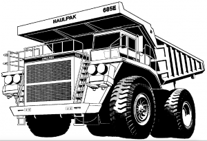
Komatsu 685E Dump Truck Factory Shop & Service Manual

Pages from DG667 – Dump Truck 685E Shop Manual

MKMTS685EOPES.PDF
Price: $29.99 USD

Complete workshop & service manual with electrical wiring diagrams for Komatsu 685E Dump Truck. It’s the same service manual used by dealers that guaranteed to be fully functional and intact without any missing page.

This Komatsu 685E Dump Truck service & repair manual (including maintenance, overhaul, disassembling & assembling, adjustment, tune-up, operation, inspecting, diagnostic & troubleshooting…) is divided into different sections. Each section covers a specific component or system with detailed illustrations. A table of contents is placed at the beginning of each section. Pages are easily found by category, and each page is expandable for great detail. The printer-ready PDF documents work like a charm on all kinds of devices.

DG667 – Dump Truck 685E Shop Manual.pdf
DG674 – Dump Truck 685E Operator handbook.pdf

EXCERPT:
TABLE OF CONTENTS
SUBJ ECT . . . . . . SECTION
GENERAL INFORMATION . . . . . . A
STRUCTURES . . . . . B
ENGINE, FUEL, COOLING AND AIR CLEANER . . . . . . C
ELECTRIC SYSTEM (2 4 VDC. NON-PROPULSION) . . . . D
ELECTRIC PROPULSION AND CONTROL . . . . . . E
DRIVE AXLE, SPINDLES AND WHEELS . . . . . . G
HYDRAIR® II SUSPENSIONS . . . . H
BRAKE CIRCUIT . . . . J
AIR SYSTEM . . . . . . K
HYDRAULIC SYSTEM . . . . . L
OPTIONS AND SPECIAL TOOLS . . . . . . M
OPERATOR’S CAB . . . . . N
LUBRICATION AND SERVICE . . . . P
ALPHABETICAL INDEX . . . Q
SYSTEM SCHEMATICS . . . . R

ENGINE COMPONENTS
THROTTLE CONTROL AIR CYLINDERS
the throttle control cylinder(s) controls the engine RPM. the cylinder is controlled by the operator’s throttle treadle valve. Various system components and the position of the engine idle switch can affect the RPM rang e available to the operator.
On Detroit Diesel engines, one cylinder provides the full rang e of engine RPM (750 to 2040 RPM) and also is designed to provide a mid range engine speed (1675 RPM) required while operating the dynamic retarding system.
On engines, two cylinders are required. the inboard cylinder provides full rang RPM (750 to 2300 RPM), the outboard cylinder controls the dynamic retarding RPM (1675 RPM).
Detroit Diesel Engine
Throttle Cylinder Removal

Posted on

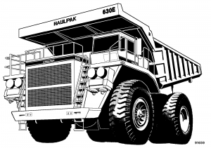
Komatsu 630E Dump Truck Factory Shop & Service Manual

Komatsu 630E Dump Truck

MKMTS630EOPES.PDF
Price: $29.99 USD

Complete workshop & service manual with electrical wiring diagrams for Komatsu 630E Dump Truck. It’s the same service manual used by dealers that guaranteed to be fully functional and intact without any missing page.

This service & repair manual for KOMATSU 630E HAULPAK TRUCK (including maintenance, overhaul, disassembling & assembling, adjustment, tune-up, operation, inspecting, diagnostic & troubleshooting…) is divided into different sections. Each section covers a specific component or system with detailed illustrations. A table of contents is placed at the beginning of each section. Pages are easily found by category, and each page is expandable for great detail. The printer-ready PDF documents work like a charm on all kinds of devices.

DG675 – Dump Truck 630E Shop Manual.pdf
DG738 – Dump Truck 630E Operation & Maintenance Manual.pdf

EXCERPT:
TABLE OF CONTENTS
GENERAL INFORMATION
STRUCTURES
ENGINE, FUEL, COOLING AND AIR CLEANER
ELECTRIC SYSTEM (24 VDC. NON-PROPULSION
ELECTRIC PROPULSION AND CONTROL
DRIVE AXLE, SPINDLES AND WHEELS
HYDRAIR® II SUSPENSIONS
BRAKE CIRCUIT
AIR SYSTEM
HYDRAULIC SYSTEM
OPTIONS AND SPECIAL TOOLS
OPERATOR’S CAB
LUBRICATION AND SERVICE
ALPHABETICAL INDEXQ
SYSTEM SCHEMATICS

AIR THROTTLE/ELECTRONIC RETARD
CONTROL
Trucks equipped with an air throttle use an air pressure modulating treadle valve to control an air cylinder attached to the engine fuel control device. (Refer to Section K for throttle treadle service information.)
The AS switch described below provides the propulsion initiation signal (AS) to the FL275 panel when the accelerator pedal is depressed.
If equipped with an air operated throttle, the truck will utilize an operator controlled, electronic retard initiation and modulation control system consisting of an electronic retard pedal and a Retard Panel [RET] (5, Figure 2-32) providing FL275 panel interface requirements.
The Retard Panel receives a variable voltage signal from the foot pedal, proportional to the angle of depression of the pedal. The RET panel provides a signal (RS) to initiate retarding and a variable voltage signal (RPINHI) proportional to the amount of retarding
effort, requested by the operator, to the FL275 panel.
For retard pedal service, refer to ”Electronic Accelerator And Retard Pedals” in this Section. For RET service and adjustment, refer to “Statex III Electrical Checkout Procedure”, Section 1.2.
Acceleration Switch [AS]