Posted on

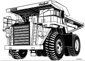
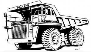
Komatsu Dump Truck 530M Factory Service & Shop Manual

Pages from CEBD008300 – Dump Truck 530M Shop Manual

MKMTS530MOPEK.PDF
Price: $29.99 USD

Complete workshop & service manual with electrical wiring diagrams for Komatsu Dump Truck 530M. It’s the same service manual used by dealers that guaranteed to be fully functional and intact without any missing page.

This Komatsu Dump Truck 530M service & repair manual (including maintenance, overhaul, disassembling & assembling, adjustment, tune-up, operation, inspecting, diagnostic & troubleshooting…) is divided into different sections. Each section covers a specific component or system with detailed illustrations. A table of contents is placed at the beginning of each section. Pages are easily found by category, and each page is expandable for great detail. The printer-ready PDF documents work like a charm on all kinds of devices.

CEBD008300 – Dump Truck 530M Shop Manual.pdf
DG716 – Dump Truck 530M Operation & Maintenance Manual.pdf

EXCERPT:
TABLE OF CONTENTS
SUBJECT . . . SECTION
GENERAL INFORMATION . . . A
STRUCTURES . . . . . B
ENGINE, FUEL, COOLING AND AIR CLEANER . . . . . . C
ELECTRIC SYSTEM (24 VDC. NON-PROPULSION) . . . . D
TRANSMISSION AND TORQUE CONVERTER . . . . . . . F
DRIVE AXLE, SPINDLES AND WHEELS . . . . . G
SUSPENSIONS . . . H
BRAKE CIRCUIT . . . . J
AIR SYSTEM (NO AIR SYSTEM ON THIS TRUCK) . . . . . . K
HYDRAULIC SYSTEM . . . . . . L
OPTIONS AND SPECIAL TOOLS . . . . M
OPERATOR’S CAB . . . . . . N
LUBRICATION AND SERVICE . . . . . . P
ALPHABETICAL INDEX . . . . Q
SYSTEM SCHEMATICS . . . . . R

Assembly
1. Refer to ‘‘Seal Replacement’’ for flange plate seal installation instructions.
2. Place rear pump body (11, Figure 3-6) so that the matching mark made in disassembly step 2 will be facing you. If a new body must be used, make sure the side facing you is the same as the one marked on the old body.
NOTE: Observe that the body has a wide and a narrow boss. The side having the wide boss is always the suction side of the body.
3. Using clean hydraulic oil, coat the inside of pump body (11).
4. Out of the group of parts from the rear section, examine the two isolation plates. You will find that they are slightly different. Choose the one having the rounded edge as shown by the arrow in Figure 3-11. With the rounded edge down, install the plate (on the suction side) in the bottom of the body.
5. Install back-up ring (7, Figure 3-12), O-ring (6), and ring retainer (2).
6. With the bronze side facing up and the rounded trap slots toward the outlet side of the body, slide pressure plate (2, Figure 3-13) down into the gear bores until it rests firmly at the bottom of the pump body. Do not force the plate down the gear bores.
If the plate hangs or binds on the way down, work it back and forth carefully until it slides freely into position.

Posted on

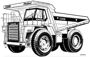
Komatsu Dump Truck 330M Factory Service & Shop Manual

Pages from DG744 – Dump Truck 330M Shop Manual

MKMTS330MOPEK.PDF
Price: $29.99 USD

Complete workshop & service manual with electrical wiring diagrams for Komatsu Dump Truck 330M. It’s the same service manual used by dealers that guaranteed to be fully functional and intact without any missing page.

This Komatsu Dump Truck 330M service & repair manual (including maintenance, overhaul, disassembling & assembling, adjustment, tune-up, operation, inspecting, diagnostic & troubleshooting…) is divided into different sections. Each section covers a specific component or system with detailed illustrations. A table of contents is placed at the beginning of each section. Pages are easily found by category, and each page is expandable for great detail. The printer-ready PDF documents work like a charm on all kinds of devices.

DG642 – Dump Truck 330M Shop Manual.pdf
DG666 – Dump Truck 330M Shop Manual.pdf
DG699 – Dump Truck 330M Shop Manual.pdf
DG713 – Dump Truck 330M Operation & Maintenance Manual.pdf
DG728 – Dump Truck 330M Shop Manual.pdf
DG729 – Dump Truck 330M Operation & Maintenance Manual.pdf
DG744 – Dump Truck 330M Shop Manual.pdf
DG745 – Dump Truck 330M Operation & Maintenance Manual.pdf

EXCERPT:
TABLE OF CONTENTS
SUBJECT . . . . SECTION
GENERAL INFORMATION . . . . A
STRUCTURES . . . . B
ENGINE, FUEL, COOLING AND AIR CLEANER . . . . . C
ELECTRIC SYSTEM (24 VDC. NON-PROPULSION) . . . . D
TRANSMISSION AND TORQUE CONVERTER . . . . . F
DRIVE AXLE, SPINDLES AND WHEELS . . . . . G
SUSPENSIONS . . . . H
BRAKE CIRCUIT . . . . . J
AIR SYSTEM . . . . . K
HYDRAULIC SYSTEM . . . . L
OPTIONS AND SPECIAL TOOLS . . . . . M
OPERATOR’S CAB . . . . N
LUBRICATION AND SERVICE . . . . P
ALPHABETICAL INDEX . . . . Q
SYSTEM SCHEMATICS . . . . . R

STEERING CIRCUIT OPERATION
The steering system is a self-metering , power steering type. When the steering wheel (5, Figure 4-1) is rotated, the steering control valve (6) is actuated causing the oil to flow into the steering cylinder (2).
Extending one steering cylinder while retracting the opposite steering cylinder will change the angle of the front wheels, allowing the operator to steer the truck as desired. the tie rod (3), attach ed to the knuckle (7 ) maintains a constant angular relationship
between the left and rig h t wheels. the truck is also equipped with an automatic emergency steering system to provide oil pressure to the steering circuit in the event of a loss of oil supply from the engine driven steering pump.

Posted on

Komatsu Dump Truck 325M Factory Service & Shop Manual

Pages from DG611 – Dump Truck 325M Shop Manual

MKMTS325MOPEK.PDF
Price: $29.99 USD

Complete workshop & service manual with electrical wiring diagrams for Komatsu Dump Truck 325M. It’s the same service manual used by dealers that guaranteed to be fully functional and intact without any missing page.

This Komatsu Dump Truck 325M service & repair manual (including maintenance, overhaul, disassembling & assembling, adjustment, tune-up, operation, inspecting, diagnostic & troubleshooting…) is divided into different sections. Each section covers a specific component or system with detailed illustrations. A table of contents is placed at the beginning of each section. Pages are easily found by category, and each page is expandable for great detail. The printer-ready PDF documents work like a charm on all kinds of devices.

DG611 – Dump Truck 325M Shop Manual.pdf

EXCERPT:
TABLE OF CONTENTS
SUBJECT . . . . . . SECTION
GENERAL INFORMATION ……… A
STRUCTURES . . . . . . B
ENGINE, FUEL, COOUNG AND AIR CLEANER . . . . . . C
ELECTRIC SYSTEM (24 VDC. NON-PROPULSION) . . . . . . D
TRANSMISSION AND PTO . . . . . . F
DRIVE AXLE, SPINDLES AND WHEELS . . . . . . G
HYDRAIR® II SUSPENSIONS . . . . . . H
BRAKE CIRCUIT . . . . . . • • . J
AIR SYSTEM . . . . . . K
HYDRAULIC SYSTEM . . . . . . L
OPTIONS AND SPECIAL TOOLS . . . . . . M
OPERATOR’S CAB . . . . . . N
LUBRICATION AND SERVICE . . . . . . P
ALPHABETICAL INDEX . . . . . . Q
SYSTEM SCHEMATICS ……….. R

Disassembly
1. Remove capscrews and washers (9, Figure 3-3) and brake drum (8). The brake drum does not need to be removed unless repair or replacement is necessary.
2. Remove oil seal (20), spacer (4), bearing cone (21) and bearing cup (5).
3. Turn wheel hub over and remove bearing cup (12).
4. Remove seal runner (3) from spindle.
Cleaning and Inspection
1. Clean all metal parts in fresh cleaning solvent.
2. Replace any worn or damaged parts.
3. Replace 0-rings and seal runner if worn or damaged.
4. Inspect wheel hub and spindle for damage.
Spindle should be checked in area of inner radius for distress after seal runner has been removed.
Non destructive testing means can be used to check for possible cracks.
Assembly
1. Press bearing cup (12) into bore of wheel hub.
NOTE: Press bearings in using a hydraulic press with sufficient force to fully seat the bearing. Use a feeler gauge to check for gaps between bearing and shoulder. Bearings which are improperly seated can cause major repair problems.
2. Turn wheel hub over and press bearing cup (5) into bore of wheel hub.
3. Place bearing cone (21) into bearing cup (5).
4. Install spacer (4) and press oil seal (20) into wheel hub bore, using care not to damage the seal during assembly.
5. Install brake drum (8) on wheel hub if brake drum was removed.
6. Press seal runner (3) onto spindle.

Posted on

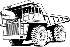
Komatsu Dump Truck 210E Factory Service & Shop Manual

Pages from DG715 – Dump Truck 210E Shop Manual

MKMTS210MOPEK.PDF
Price: $29.99 USD

Complete workshop & service manual with electrical wiring diagrams for Komatsu Dump Truck 210E. It’s the same service manual used by dealers that guaranteed to be fully functional and intact without any missing page.

This Komatsu Dump Truck 210E service & repair manual (including maintenance, overhaul, disassembling & assembling, adjustment, tune-up, operation, inspecting, diagnostic & troubleshooting…) is divided into different sections. Each section covers a specific component or system with detailed illustrations. A table of contents is placed at the beginning of each section. Pages are easily found by category, and each page is expandable for great detail. The printer-ready PDF documents work like a charm on all kinds of devices.

DG610 – Dump Truck 210E Shop Manual.pdf
DG615 – Dump Truck 210E Operation & Maintenance Manual.pdf
DG692 – Dump Truck 210E Operation & Maintenance Manual.pdf
DG694 – Dump Truck 210E Shop Manual.pdf
DG714 – Dump Truck 210E Operation & Maintenance Manual.pdf
DG715 – Dump Truck 210E Shop Manual.pdf
DG725 – Dump Truck 210E Operation & Maintenance Manual.pdf

EXCERPT:
TABLE OF CONTENTS
SUBJECT . . . . . SECTION
GENERAL INFORMATION . . . . . A
STRUCTURES . . . . . . . . . . . . B
ENGINE, FUEL, COOLING AND AIR CLEANER . . . . . . . C
ELECTRIC SYSTEM (24 VDC. NON-PROPULSION) . . . . . D
TRANSMISSION AND PTO . . . . . F
DRIVE AXLE, SPINDLES AND WHEELS . . . . . . . . G
HYDRAIR® II SUSPENSIONS . . . . . . H
BRAKE CIRCUIT . . . . . . . . . . . J
HYDRAULIC SYSTEM . . . . . . . . L
OPTIONS AND SPECIAL TOOLS . . . . . . . . . . . . M
OPERATOR’S CAB . . . . . . . . N
LUBRICATION AND SERVICE . . . . . . P
ALPHABETICAL INDEX . . . . . . Q
SYSTEM SCHEMATICS . . . . . . . R

STEERING CONTROL VALVE
Removal
1. Shut down engine and bleed down steering circuit.
Allow at least 90 seconds for system to bleed.
Open the manual bleeddown valves to release the pressure from the brake accumulators.
NOTE: To insure the hydraulic oil has completely drained from the accumulator, turn the steering wheel.
If the wheels do not turn, all the hydraulic pressure has been drained from accumulator.
2. Clean exterior of steering control valve thoroughly.
3. Tag and disconnect hydraulic lines. Plug lines and ports securely to prevent spillage and possible contamination to the system.
4. Remove capscrews at flange (3, Figure 5-1).
Remove nuts (6), washers (7 & 8) and capscrew at each rubber bushing. Lower and remove valve.
Installation
1. Assemble steering control valve (10, Figure 5-1) to mounting plate (11). Insert assembly through bottom of cab floor and align splines on valve column (4) with the flange assembly (3). Install capscrews (9), from bottom side of mounting
plate, through the rubber bushings (12). Install flatwashers, lockwashers and nuts. Tighten to standard torque.
2. Install capscrews in flange (3) and tighten to standard torque.
3. Remove caps from hydraulic lines. Be certain that previously tagged lines are connected to their respective ports according to the markings on the steering control valve assembly.

Posted on

Komatsu Dump Trucks 140M Factory Service & Shop Manual

DG693 – Dump Truck 140M Shop Manual

MKMTS140MOPEK.PDF
Price: $29.99 USD

Complete workshop & service manual with electrical wiring diagrams for Komatsu Dump Trucks 140M. It’s the same service manual used by dealers that guaranteed to be fully functional and intact without any missing page.

This Komatsu Dump Trucks 140M service & repair manual (including maintenance, overhaul, disassembling & assembling, adjustment, tune-up, operation, inspecting, diagnostic & troubleshooting…) is divided into different sections. Each section covers a specific component or system with detailed illustrations. A table of contents is placed at the beginning of each section. Pages are easily found by category, and each page is expandable for great detail. The printer-ready PDF documents work like a charm on all kinds of devices.

DG693 – Dump Truck 140M Shop Manual.pdf

EXCERPT:
TABLE OF CONTENTS
SUBJECT . . . . . . SECTION
GENERAL INFORMATION ………………….. A
STRUCTURES . . . . . . . . . B
ENGINE, FUEL, COOLING AND AIR CLEANER . . . . . . C
ELECTRIC SYSTEM (24 VDC. NON-PROPULSION) . . . . . . . . D
TRANSMISSION AND PTO . . . . . . F
DRIVE AXLE, SPINDLES AND WHEELS . . . . . . G
HYDRAIR® II SUSPENSIONS . . . . . . . . H
BRAKE CIRCUIT . . . . . . . . J
HYDRAULIC SYSTEM . . . . . . . . L
OPTIONS AND SPECIAL TOOLS . . . . . M
OPERATOR’S CAB . . . . . . . . . N
LUBRICATION AND SERVICE ………………… P
ALPHABETICAL INDEX . . . . . . . . Q
SYSTEM SCHEMATICS ………. R

RADIATOR SHUTTERS
TEMPERATURE CONTROL CIRCUIT
The temperature control system contains a solenoid valve, temperature switch and relay, shutter control cylinder, radiator shutter assembly and the necessary hoses and wiring for operation.
OPERATION
Hydraulic pressure to operate the shutters is supplied from a pilot port on the auxiliary manifold and directed to the solenoid valve located on the right side of the radiator top tank.
On engine start up, the solenoid valve will be in its normally open position, allowing oil pressure to be applied to the shutter control cylinder to move the shutters to a fully closed position. This blocks air flow through the radiator to speed the warm up of coolant through the system.
The 24 volt unswitched side of the engine oil pressure switch supplies 24 volts to the solenoid switch.