Posted on

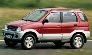
1994-2007 Daihatsu Cuore, GranMove, Move, Terios Workshop Repair & Service Manual in German language (4,500 Pages, Searchable, Printable, Bookmarked, iPad-ready PDF)

1994-2007 Daihatsu Cuore, GranMove, Move, Terios Workshop Repair & Service Manual in German language (4,500 Pages, Searchable, Printable, Bookmarked, iPad-ready PDF)

MDHTMISC9407OPDK
Price: $9.99 USD

1994-2007 Daihatsu Cuore, GranMove, Move, Terios Workshop Repair & Service Manual in German language (4,500 Pages, Searchable, Printable, Bookmarked, iPad-ready PDF)

Complete digital workshop service and repair manual written for the Daihatsu Cuore, GranMove, Move, Terios; Production model years: 1994 1995 1996 1997 1998 1999 2000 2001 2002 2003 2004 2005 2006 2007. All styles covered (all models, and engines). It is in the cross-platform PDF document format so that it works like a charm on all kinds of devices.

This QUALITY manual is 100% COMPLETE and INTACT, no MISSING/CORRUPT pages/sections to freak you out! Buy from responsible seller and get INSTANT DOWNLOAD now without wasting your hard-owned money on uncertainty or surprise; this manual is exactly as described.

MAKE: Daihatsu
MODEL:
Cuore (Mira, Domino, Handi/Handivanm, Charade) (Model L500, L501 Series) (’94-’98)
Cuore (Mira, Charade) (Model L251 Series) (’02-’07)
GranMove (Pyzar, Grand Move) (Model G301, G303 Series) (’96-’02)
Move (Model L601 Series) (’95-’01)
Terios (Model G100, G102, G122 Series) (’97-’04)
YEAR: 1994 1995 1996 1997 1998 1999 2000 2001 2002 2003 2004 2005 2006 2007
LANGUAGE: German (DE)

PRODUCT DETAILS:
Total Pages: more than 4,500 pages
File Format: PDF (Windows & Mac & Linux)
Language: German
Delivery: instant download link displayed on checkout page & emailed to you after payment
Protection: DRM-free; without any restriction
Printable: Yes

This COMPLETE official full workshop service repair manual includes:
* Detailed sub-steps expand on repair procedure information
* Notes, cautions and warnings throughout each chapter pinpoint critical information.
* Numbered instructions guide you through every repair procedure step by step.
* Bold figure number help you quickly match illustrations with instructions.
* Detailed illustrations, drawings and photos guide you through every procedure.
* Enlarged inset helps you identify and examine parts in detail.
* Numbered table of contents easy to use so that you can find the information you need fast.
* This manual also makes it easy to diagnose and repair problems with your machines electrical system.
* Troubleshooting and electrical service procedures are combined with detailed wiring diagrams for ease of use.

* COMPLETE, Absolutely No Missing Pages!
* Official Service INFORMATION You Can Count On!
* Customer Satisfaction GUARANTEED!

EXCERPT (1994-2007 Daihatsu Cuore, GranMove, Move, Terios Service/Repair Manual):
A.ALLGEMEINE INFORMATIONEN
ALLGEMEINE INFORMATIONEN
WARTUNG
B.MOTOR
MOTOR
MOTORBAUTEILE
ANSAUGSYSTEM
ABGASANLAGE
SCHMIERSYSTEM
KÜHLSYSTEM
KRAFTSTOFFSYSTEM
MOTORSTEUERUNGSSYSTEM
EMISSIONSSTEUERUNGSSYSTEM
ZÜNDANLAGE
ANLASSERSYSTEM/LADESYSTEM
MOTORAUFHÄNGUNG
C.AUFHÄNGUNG
VORDERRADAUFHÄNGUNG
HINTERRADAUFHÄNGUNG
D.ANTRIEB/ACHSE
ANTRIEBSWELLE/GELENKWELLE/ACHSE
E.BREMSE
BREMSE
HANDBREMSE
BREMSENSTEUERUNG
F.GETRIEBE
KUPPLUNG
SCHALTGETRIEBE
AUTOMATIKGETRIEBE
G.LENKUNG
LENKUNG
SERVOLENKUNG
LENKSYSTEM OHNE ELEKTR. STEUERUNG
H.SRS-AIRBAG
SRS-AIRBAG SYSTEM
I.KAROSSERIE
KAROSSERIE
AUSSEN- UND INNENAUSSTATTUNG
WINDSCHUTZSCHEIBE, SEITENSCHEIBEN, SPIEGEL
ZENTRALVERRIEGELUNG & WEGFAHRSPERRE
J. KAROSSERIEELEKTRIK
BELEUCHTUNG
SCHEIBENWISCHER&SCHEIBENWASCHANLAGE
KOMBIINSTRUMENT
AUDIOVISUELLES SYSTEM
HAUPTSICHERUNG
K. HEIZUNG UND KLIMAANLAGE
HEIZUNG & KLIMAANLAGE

2. Den vorderen Satellitensensor ausbauen.
8-1-5 ÜBERPRÜFUNG
(1) PRÜFSTANDARD FÜR DEN VORDEREN SATELLITENSENSOR
1. Überprüfung des vorderen Satellitensensors in den folgenden Fällen. Wenn die Einheit fehlerhaft ist, austauschen.
(1) Wenn das Fahrzeug in eine Kollision verwickelt wurde.
VORSICHT
• Test unabhängig davon durchführen, ob der Airbag ausgelöst wurde oder nicht.
• Nach Auslösen des Airbags sicherstellen, dass dieser gegen einen neuen ausgetauscht wird.
• Beim Testverfahren die Anweisungen zur Überprüfung der Einheit befolgen.
Siehe Seite H1-112.
(2) Überprüfung der äußeren Erscheinung des vorderen Satellitensensors
1. Austausch des vorderen Satellitensensors in den folgenden Fällen.
(1) Wenn der vordere Satellitensensor heruntergefallen ist.
(2) Wenn der Verbinderbereich beschädigt ist oder Risse aufweist.
(3) Wenn der vordere Satellitensensor Verformungen und Risse aufweist.

MDHTMISC9407OPDK
Price: $9.99 USD

Posted on

2004-2006 Harley Davidson Sportster Motorcycle Workshop Repair & Service Manual (462 Pages, Searchable, Printable, Bookmarked, iPad-ready PDF)

2004-2006 Harley Davidson Sportster Motorcycle Workshop Repair & Service Manual (462 Pages, Searchable, Printable, Bookmarked, iPad-ready PDF)

MHDSP0406OPEK
Price: $12.99 USD

2004-2006 Harley Davidson Sportster Motorcycle Workshop Repair & Service Manual (462 Pages, Searchable, Printable, Bookmarked, iPad-ready PDF)

Complete digital workshop service and repair manual written for the Harley Davidson Sportster Motorcycle; Production model years: 2004 2005 2006. All styles covered (all models, and engines). It is in the cross-platform PDF document format so that it works like a charm on all kinds of devices.

This QUALITY manual is 100% COMPLETE and INTACT, no MISSING/CORRUPT pages/sections to freak you out! Buy from responsible seller and get INSTANT DOWNLOAD now without wasting your hard-owned money on uncertainty or surprise; this manual is exactly as described.

PRODUCT DETAILS:
Total Pages: 462 pages
File Format: PDF (Windows & Mac & Linux)
Language: English
Delivery: instant download link displayed on checkout page & emailed to you after payment
Protection: DRM-free; without any restriction
Printable: Yes

This COMPLETE official full workshop service repair manual includes:
* Detailed sub-steps expand on repair procedure information
* Notes, cautions and warnings throughout each chapter pinpoint critical information.
* Numbered instructions guide you through every repair procedure step by step.
* Bold figure number help you quickly match illustrations with instructions.
* Detailed illustrations, drawings and photos guide you through every procedure.
* Enlarged inset helps you identify and examine parts in detail.
* Numbered table of contents easy to use so that you can find the information you need fast.
* This manual also makes it easy to diagnose and repair problems with your machines electrical system.
* Troubleshooting and electrical service procedures are combined with detailed wiring diagrams for ease of use.

* COMPLETE, Absolutely No Missing Pages!
* Official Service INFORMATION You Can Count On!
* Customer Satisfaction GUARANTEED!

EXCERPT (2004-2006 Harley Davidson Sportster Motorbike Service/Repair Manual):
1 Chapter One General Information
2 Chapter Two Troubleshooting
3 Chapter Three Periodic Lubrication, Maintenance & Tune-up
4 Chapter Four Engine Top End
5 Chapter Five Engine Lower End
6 Chapter Six Primary Drive, Clutch & External Shift Mechanism
7 Chapter Seven Transmission & Internal Shift Mechanism
8 Chapter Eight Fuel, Emission Control & Exhaust Systems
9 Chapter Nine Electrical System
10 Chapter Ten Wheels, Tires & Drive Belt
11 Chapter Eleven Front Suspension & Steering
12 Chapter Twelve Rear Suspension
13 Chapter Thirteen Brakes
14 Chapter Fourteen Body
15 Chapter Fifteen Index
16 Chapter Sixteen Wiring Diagrams

INNER ROCKER COVERS
The outer and inner rocker covers (Figure 1) can be removed from either cylinder with the engine installed in the frame. The outer rocker cover sits on top of the inner rocker cover, which contains the rocker arms and shafts.
Cover Removal
1. Remove the air cleaner backplate as described in Chapter Eight.
2. Remove the outer rocker cover as described in this chapter.
NOTE
Steps 3A and 3B describe two methods for turning the engine over by hand. When performing Step 3A, the bike must be supported with the rear wheel off the ground.
3A. Shift the transmission into fifth gear. While watching the rocker arms, turn the rear wheel until both valves are closed on the cylinder being serviced.
3B. Remove the primary cover as described in Chapter
Six. While watching the rocker arms, turn the engine sprocket nut (with a socket and ratchet) until both valves are closed on the cylinder being serviced.
4. Remove the socket head bolts and washers (A, Figure 6).
5. Remove the bolts and washer (B, Figure 6).
6. Remove the four rocker arm mounting bolts and washers (C, Figure 6) by unscrewing each bolt 1/4 turn in a crossing pattern.
7. Remove the lower rocker cover (A, Figure 7). Discard the gasket.
Cover Installation
1. Install a new gasket (A, Figure 8) with the sealer bead facing up.
2. Place the lower rocker cover into position (A, Figure 7), while at the same time inserting the pushrods (B, Figure 8) into the rocker arm sockets (B, Figure 7).
CAUTION To ensure proper installation and tappet.


MHDSP0406OPEK
Price: $12.99 USD

Posted on

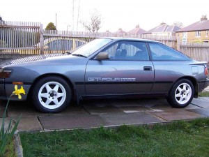
1988 Toyota Celica Workshop Repair & Service Manual (1,338, Searchable, Printable iPad-ready PDF)

1988 Toyota Celica Workshop Repair & Service Manual (1,338, Searchable, Printable iPad-ready PDF)

MTYTCLC88OPES
Price: $9.99 USD

1988 Toyota Celica Workshop Repair & Service Manual (1,338, Searchable, Printable iPad-ready PDF)

Complete digital workshop service and repair manual written for the 1988 Toyota Celica. All styles covered (all models, and engines). It is in the cross-platform PDF document format so that it works like a charm on all kinds of devices.

This QUALITY manual is 100% COMPLETE and INTACT, no MISSING/CORRUPT pages/sections to freak you out! Buy from responsible seller and get INSTANT DOWNLOAD now without wasting your hard-owned money on uncertainty or surprise; this manual is exactly as described.

PRODUCT DETAILS:
Total Pages: more than 1,338 pages
File Format: PDF (Windows & Mac & Linux)
Language: English
Delivery: instant download link displayed on checkout page & emailed to you after payment
Protection: DRM-free; without any restriction
Printable: Yes

This COMPLETE full workshop service repair manual includes:
* Detailed sub-steps expand on repair procedure information
* Notes, cautions and warnings throughout each chapter pinpoint critical information.
* Numbered instructions guide you through every repair procedure step by step.
* Bold figure number help you quickly match illustrations with instructions.
* Detailed illustrations, drawings and photos guide you through every procedure.
* Enlarged inset helps you identify and examine parts in detail.
* Numbered table of contents easy to use so that you can find the information you need fast.
* This manual also makes it easy to diagnose and repair problems with your machines electrical system.
* Troubleshooting and electrical service procedures are combined with detailed wiring diagrams for ease of use.
* COMPLETE, Absolutely No Missing Pages!
* Customer Satisfaction GUARANTEED!

EXCERPT (1988 Toyota Celica Service/Repair Manual):
TRANSMISSION REMOVAL & INSTALLATION – A/T
1988 Toyota Celica
1988 AUTOMATIC TRANSMISSION REMOVAL
Toyota Camry & Celica (2WD)
NOTE: The torque converter drive plate runout for all Toyota models is .008″ (.20 mm). Measure runout on face of drive plate as close to ring gear as possible.
REMOVAL
1) Disconnect negative battery cable. Remove airflow meter and air cleaner. Disconnect neutral safety switch connector and all external electrical connectors. Remove ground strap.
2) Disconnect transaxle throttle valve cable at throttle linkage and remove cable from bracket. Remove transaxle case protector and disconnect speedometer cable. Disconnect shift control cable at lever and remove from bracket.
3) Disconnect oil cooler hoses and remove starter motor bolts. Remove 2 upper transaxle-to-engine bolts. Remove insulator bracket set bolt for rear engine mount. Raise and support vehicle.
4) Drain transaxle oil. Disconnect and plug oil cooler hoses. Remove left front fender apron. Disconnect both axle shafts
from transaxle. Remove lower suspension crossmember. Using pliers, remove snap ring on center axle shaft bearing bracket. Remove bearing bracket bolt and pull center axle shaft assembly out.
5) Disconnect control cable clamp and remove crossmember bolts supporting center mounts of engine. Remove crossmember. Remove
stabilizer bar and left steering knuckle from lower control arm. Pull steering knuckle outward and remove left axle shaft.
6) Remove bellhousing cover and remove 6 bolts attaching torque converter to drive plate. On Camry, remove engine-to-transmission stiffener plate.
7) On all models, support engine with jack stand and secure transaxle jack under transaxle. Lower rear end of transaxle and
remove remaining transaxle-to-engine bolts. Separate transaxle from engine and lower transaxle assembly.
INSTALLATION
1) Apply multipurpose grease to center hub of torque converter. Install one guide pin in threaded mounting pad of torque converter to aid in aligning torque converter. Distance from torque converter drive lug to engine mating surface of transaxle should be at least .51″ (13 mm).
2) Reverse removal procedure to complete installation of transaxle. Torque converter bolts are color coded. Install Gray bolt first, then the remaining 5 bolts. Tighten torque converter bolts to 20 ft. lbs. (27 N.m).


MTYTCLC88OPES
Price: $9.99 USD

Posted on

1997-2002 Toyota Avensis/Corona Workshop Repair & Service Manual (3,799 Pages, Searchable, Printable, Bookmarked, iPad-ready PDF)

1997-2002 Toyota Avensis/Corona Workshop Repair & Service Manual (3,799 Pages, Searchable, Printable, Bookmarked, iPad-ready PDF)

MTYTAVS9702OPES
Price: $9.99 USD

1997-2002 Toyota Avensis/Corona Workshop Repair & Service Manual (3,799 Pages, Searchable, Printable, Bookmarked, iPad-ready PDF)

Complete digital workshop service and repair manual written for the Toyota Avensis/Corona; Production model years: 1997 1998 1999 2000 2001 2002. All styles covered (all models, and engines). It is in the cross-platform PDF document format so that it works like a charm on all kinds of devices.

This QUALITY manual is 100% COMPLETE and INTACT, no MISSING/CORRUPT pages/sections to freak you out! Buy from responsible seller and get INSTANT DOWNLOAD now without wasting your hard-owned money on uncertainty or surprise; this manual is exactly as described.

PRODUCT DETAILS:
Total Pages: 3,799 pages
File Format: PDF (Windows & Mac & Linux)
Language: English
Delivery: instant download link displayed on checkout page & emailed to you after payment
Protection: DRM-free; without any restriction
Printable: Yes

Applicable models: AT220, 221 series, ST220 series, CT220 series, CDT220 series, AZT220 series, ZZT220, 221 series

This COMPLETE official full workshop service repair manual includes:
* Detailed sub-steps expand on repair procedure information
* Notes, cautions and warnings throughout each chapter pinpoint critical information.
* Numbered instructions guide you through every repair procedure step by step.
* Bold figure number help you quickly match illustrations with instructions.
* Detailed illustrations, drawings and photos guide you through every procedure.
* Enlarged inset helps you identify and examine parts in detail.
* Numbered table of contents easy to use so that you can find the information you need fast.
* This manual also makes it easy to diagnose and repair problems with your machines electrical system.
* Troubleshooting and electrical service procedures are combined with detailed wiring diagrams for ease of use.

* COMPLETE, Absolutely No Missing Pages!
* Official Service INFORMATION You Can Count On!
* Customer Satisfaction GUARANTEED!

EXCERPT (1997-2002 Toyota Avensis/Corona Service/Repair Manual):
MANUAL TRANSAXLE (E251)
TROUBLESHOOTING . . . . . . . . . . . . . . . . . . . .
MANUAL TRANSAXLE UNIT . . . . . . . . . . . . . .
MANUAL TRANSAXLE ASSEMBLY . . . . . . . .
INPUT SHAFT . . . . . . . . . . . . . . . . . . . . . . . . . . .
OUTPUT SHAFT . . . . . . . . . . . . . . . . . . . . . . . . .
OIL PUMP . . . . . . . . . . . . . . . . . . . . . . . . . . . . . .
SHIFT AND SELECT LEVER SHAFT . . . . . . .
DIFFERENTIAL CASE . . . . . . . . . . . . . . . . . . . .
SHIFT LEVER AND CONTROL CABLE . . . . .
REASSEMBLY
Reassembly is in the reverse order of disassembly. (See page MX–12)
NOTICE: When working with FIPG material, you must observe the following items.
Using a razor blade and gasket scraper, remove all the old FIPG material from the gasket surfaces.
Thoroughly clean all components to remove all the loose material.
Clean both sealing surfaces with a non–residue solvent.
Apply FIPG in an approx. 1 mm (0.04 in.) wide bead along the sealing surface.
Parts must be assembled within 10 minutes of application. Otherwise, the FIPG material must be removed and reapplied.
HINT: Before reassembly, select a shim by adjusting output shaft preload.
Coat all of the sliding and rotating surfaces with gear oil before reassembly.
ADJUST OUTPUT SHAFT PRELOAD
(a) Install the output shaft assembly to the transaxle case.
(b) Install the transmission case to the transaxle case.
HINT:
If necessary, tap on the case with a plastic hammer.
(c) Install and torque the 17 bolts.
Torque: 29 N·m (300 kgf·cm, 22 ft·lbf)
(d) Install the output shaft rear taper roller bearing outer race.
(e) Install the adjusting shim.
HINT:
When reusing the output shaft bearing, first install a shim of the same thickness as before. If installing a new taper roller bear-
ing, first select and install a shim of lesser thickness than before.
(f) Install the rear bearing retainer.
(g) Using a torx wrench (T45), install and torque the 7 torx screws.
Torque: 42 N·m (430 kgf·cm, 31 ft·lbf)
(h) Install a new lock nut to the output shaft.
(i) Turn the output shaft right and left 2 or 3 times to allow the bearing to settle.


MTYTAVS9702OPES
Price: $9.99 USD

Posted on

Renault Trucks (Kerax, Magnum, Magnum E-Tech, Mascott, Midlum, Premiun Series) Workshop Service Repair Manual 1990-2012 (3.8GB, 8,670 pages iPad-Ready PDF)

Renault Trucks (Kerax, Magnum, Magnum E-Tech, Mascott, Midlum, Premiun Series) Workshop Service Repair Manual 1990-2012 (3.8GB, 8,670 pages iPad-Ready PDF)

MRNTRK9012OPEK
Price: $19.99 USD

Renault Trucks (Kerax, Magnum, Magnum E-Tech, Mascott, Midlum, Premiun Series) Workshop Service Repair Manual 1990-2012 (3.8GB, 8,670 pages iPad-Ready PDF)

Complete digital workshop service and repair manual written for the Renault Trucks (Kerax, Magnum, Magnum E-Tech, Mascott, Midlum, Premiun Series) ; Production model years: 1990, 1991, 1992, 1993, 1994, 1995, 1996, 1997, 1998, 1999, 2000, 2001, 2002, 2003, 2004, 2005, 2006, 2007, 2008, 2009, 2010, 2011, 2012. All styles covered. It is in the cross-platform PDF document format so that it works like a charm on all kinds of devices.

This QUALITY manual is 100% COMPLETE and INTACT, no MISSING/CORRUPT pages/sections to freak you out! Buy from responsible seller and get INSTANT DOWNLOAD now without wasting your hard-owned money on uncertainty or surprise; this manual is exactly as described.

PRODUCT DETAILS:
Total Pages: 8,670 pages
File Format: PDF (Windows & Mac & Linux)
Language: English
Delivery: instant download link displayed on checkout page & emailed to you after payment
Protection: DRM-free; without any restriction
Printable: Yes

This COMPLETE official full workshop service repair manual includes:
* Detailed sub-steps expand on repair procedure information
* Notes, cautions and warnings throughout each chapter pinpoint critical information.
* Numbered instructions guide you through every repair procedure step by step.
* Bold figure number help you quickly match illustrations with instructions.
* Detailed illustrations, drawings and photos guide you through every procedure.
* Enlarged inset helps you identify and examine parts in detail.
* Numbered table of contents easy to use so that you can find the information you need fast.
* This manual also makes it easy to diagnose and repair problems with your machines electrical system.
* Troubleshooting and electrical service procedures are combined with detailed wiring diagrams for ease of use.

* COMPLETE, Absolutely No Missing Pages!
* Official Service INFORMATION You Can Count On!
* Customer Satisfaction GUARANTEED!

EXCERPT (1990-2012 Renault Trucks Service/Repair Manual):
Exhaust manifold
Removal / Fitting
Removal
Disconnect flexible oil pipe (2).
Remove oil return pipe (1).
Remove the exhaust manifold unit with the turbocharger.
Fitting
Install bolts (3) in locations.
Fit new gaskets (1).
Ensure the marking.
Fit exhaust manifold (2).
Tighten bolts (3) to torque.
See page(s) B-5-5.
For the rest of the fitting operations, proceed in the reverse sequence to removal.
Replace seals.
Tighten to torque.
See page(s) B-5-21.
To facilitate the assembly of this type of seal in its
housing, mount it on the fitting tube and lubricate the
outside with engine oil if it is a green or violet seal or with
engine coolant if it is a black seal.
Steering pump
Removal / Fitting
Removal
Remove power-assisted steering pump (1).
Fitting
To fit, proceed in the reverse sequence to removal.
Replace O-ring with a new O-ring.
Tighten the bolts to torque.
See page(s) B-5-23.

├── BODY ASSEMBLY INSTRUCTIONS
│   ├── 354-ADD AN PREMIUM-KERAX.pdf
│   ├── 364-1 AN MASCOTT.pdf
│   ├── 364-3 AN MASCOTT.pdf
│   ├── 364-4 AN MASCOTT.pdf
│   ├── 366-1 AN PREMIUM.pdf
│   ├── 366-3 AN MIDLUM.pdf
│   ├── 366-4 AN MIDLUM.pdf
│   ├── 368-2 AN MAGNUM E-TECH.pdf
│   ├── 368-3 AN MAGNUM E-TECH.pdf
│   ├── 369-1 AN KERAX.pdf
│   ├── 369-2 AN KERAX.pdf
│   ├── 370-1 AN PREMIUM.pdf
│   └── 370-2 AN PREMIUM.pdf
├── INSTRUCTIONS
│   ├── 3914AN.pdf
│   ├── 3926 AN PREMIUM DXi.pdf
│   ├── Heater.pdf
│   ├── NE 1-3922 EN-MAGNUM DXI.PDF
│   └── NE6 3911GB-MIDLUM.pdf
├── ls
├── REPAIR MANUAL
│   ├── 13 030 FR-RU.pdf
│   ├── 13 031 FR-RU.pdf
│   ├── 13 032 FR-AN.pdf
│   ├── 13 042GB-6×4-6×6-8×4.pdf
│   ├── 13 053 AN SUSPENSION PREMIUM DXi.pdf
│   ├── 13 053 FR suspension.pdf
│   ├── 20 079GB-06 20 45-06 23 56.pdf
│   ├── 20 080GB-MIDR 06 20 45 EQUIPMENT – MIDR 06 23 56.pdf
│   ├── 20 094GB-DCI 11 EQUIPMENT.pdf
│   ├── 20095-DCI 6 EQUIPMENTEN.pdf
│   ├── 20095-DCI 6 EQUIPMENT.pdf
│   ├── 20099GB.pdf
│   ├── 20 104GB.pdf
│   ├── 20 107 FR PROJET MOTEUR DXI 11 ET EQUIP.pdf
│   ├── 20 601 AN-FR PARTIE.pdf
│   ├── 20 634 FR-RU.pdf
│   ├── 20 644 AN.pdf
│   ├── 20 651.pdf
│   ├── 20 656GB.pdf
│   ├── 20 657GB.pdf
│   ├── 20 660 AN ENGINE DCI 11.pdf
│   ├── 20 661 EN Engine.pdf
│   ├── 20 662GB.pdf
│   ├── 20 664 AN DXI 11 Engine.pdf
│   ├── 20 664 FR Moteur DXI11.pdf
│   ├── 27 622 FR.RU.pdf
│   ├── 27 623 FR.RU.pdf
│   ├── 27 626 AN.pdf
│   ├── 31 021GB-ALL TYPES.pdf
│   ├── 31 022GB-310DTR-350DTR-MFZ395-362DBE-395DBE.pdf
│   ├── 31 026GB.pdf
│   ├── 31 028GB.pdf
│   ├── 31 029 EN Embrayage.PDF
│   ├── 31 030 AN PREMIUM DXi.pdf
│   ├── 31 030 FR Embrayage.pdf
│   ├── 31 611 FR-RU.pdf
│   ├── 32 053 FR.RU.pdf
│   ├── 32 056-ZF S 6.300-5.200.pdf
│   ├── 32 068GB.pdf
│   ├── 32 643 AN.pdf
│   ├── 32 650 AN.pdf
│   ├── 32 661 EN Optidriver II.pdf
│   ├── 32 665 FR BOITE DE VITESSES 6S850.pdf
│   ├── 36 001 GB.pdf
│   ├── 36 618 FR-AN.pdf
│   ├── 36 619 FR-AN.pdf
│   ├── 36 620 AN.pdf
│   ├── 36 621-PAM 0631-0632-PAM 1131-1132.pdf
│   ├── 41 031 FR.RU.pdf
│   ├── 41 032-PAS.pdf
│   ├── 41 039GB.pdf
│   ├── 41 042GB.pdf
│   ├── 41 045GB.pdf
│   ├── 41 623GB-ZF 8095-ZF 8098.pdf
│   ├── 41 627 AN.pdf
│   ├── 42 034 FR.RU.pdf
│   ├── 42 038 ML.pdf
│   ├── 42 048GB-E 80.pdf
│   ├── 42 051GB-E 60 C.LISA-E 60 PAN 19.pdf
│   ├── 42 054GB.pdf
│   ├── 44 001GB-ER 8-ER 11-AUSTERAS.pdf
│   ├── 44 002 AN.pdf
│   ├── 47 030 FR.RU.pdf
│   ├── 47 641GB.pdf
│   └── 47 646 EN Pont M.pdf
├── REPAIR MANUAL 2
│   ├── 50 081 FR-RU.pdf
│   ├── 50 086 AN.pdf
│   ├── 50 098GB.pdf
│   ├── 50 098 Schema.pdf
│   ├── 50 101 AN.pdf
│   ├── 50 102 AN.pdf
│   ├── 50 104 AN.pdf
│   ├── 50 618 FR.AN.pdf
│   ├── 50 623 AN.pdf
│   ├── 51 634 EN Disc breaks.pdf
│   ├── 53 110 EN EBS.pdf
│   ├── 53 114 AN EBS.pdf
│   ├── 60 020 FR.RU.pdf
│   ├── 60 023GB- CAB X24-AIR BAG.pdf
│   ├── 60 024GB.pdf
│   ├── 60 027GB.pdf
│   ├── 60 613 FR.RU.pdf
│   ├── 60 629 AN.pdf
│   ├── 63 601 FR.AN.pdf
│   ├── 63 603 FR.RU.pdf
│   ├── 63 611 AN.pdf
│   ├── 70 068 FR-RU.pdf
│   ├── 70 083GB- KERAX.pdf
│   ├── 70 084- MAGNUM 390-430-470-560.pdf
│   ├── 70 099 AN.pdf
│   ├── 70 100 AN MIDLUM DCi ELECTRICITE.pdf
│   ├── 70 104- MAGNUM E. TECH.pdf
│   ├── 70 116 AN MAGNUM E-TECH ELECTRICITE.pdf
│   ├── 70 117 AN.pdf
│   ├── 70 123 AN KERAX DCi ELECTRICITE.pdf
│   ├── 70 127 AN.pdf
│   ├── 70 128 AN PREMIUM ELECTRICITE.pdf
│   ├── 70 139 AN MIDLUM ELECTRICITE.pdf
│   ├── 70 141 FR.pdf
│   ├── 70 142 EN Elec.pdf
│   ├── 70 143 EN Elec.pdf
│   ├── 70 144 EN Elec.pdf
│   ├── 70 144 FR MAGNUM DXI12.pdf
│   ├── 70 149 AN Electrics.pdf
│   ├── 70 150 EN Elec.pdf
│   ├── 70 150 FR PROJET DXI.pdf
│   ├── 70 602 FR PROJET MID128 EECU.pdf
│   ├── 70 603 FR PROJET MID130 ECU BV.pdf
│   ├── 70 603 FR version1 MID130 BOITE DE VITESSE.pdf
│   ├── 70 604 FR PROJET MID136 Diagnostic EBS.pdf
│   ├── 70 604 FR version2 MID136 Diagnostic EBS.pdf
│   ├── 70 605 FR PROJET MID144 VECU MAGNUM DXi.pdf
│   ├── 70 606 FR version1 MID 223 LEVIER DE VITESSE.pdf
│   ├── 70 608 FR PROJET MID150 ECU SUSPENSIONS.pdf
│   ├── 70 608 FR version1 MID 150 SUSPENSIONS.pdf
│   ├── 70 609 FR version1 MID 214 ANTIVOL MAGNUM DXi.pdf
│   ├── 70 610 FR version1 MID 179 GESTION DE FLOTTE.pdf
│   ├── 70 611 FR PROJET MID163 ANTIDEMARRAGE MAGNUM DXi.pdf
│   ├── 70 611 FR versoin1 MID 163 ANTIDEMARRAGE.pdf
│   ├── 70 612 FR version1 MID 249 MODULE CARROSSIER.pdf
│   ├── 70 613 FR version1 MID 140 AFFICHEUR.pdf
│   ├── 70 614 FR version2 MID 185 GONFLAGE BOBONNES D’AIR.pdf
│   ├── 70 615 FR version1 MID 216 GESTION FEUX.pdf
│   ├── 70 619 FR version1 MID 141 DATAMAX GATEWAY.pdf
│   ├── 70 901 FR MISE EN OEUVRE CONNECTIQUE.pdf
│   └── 70 902 FR PREPARATION DES FAISCEAUX.pdf
└── STAND BILLINGHOURS
├── BILLING TIMES MANUAL.pdf
├── MT142_M200 230_250.doc
├── MT142new.doc
├── Mt162_R420.doc
├── Mt163_AE420.doc
├── Mt167_HR385.doc
├── Mt172_AE390_430_470.doc
├── MT_174.xml_en.pdf
├── MT180_Midlum135_150.doc
├── MT_180.xml_en.pdf
├── MT181.doc
├── MT_181.xml_en.pdf
├── MT_182.xml_en.pdf
├── MT183_HR420.DOC
├── MT_183.xml_en.pdf
└── MT_209.xml_en.pdf


MRNTRK9012OPEK
Price: $19.99 USD