Posted on

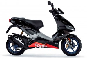
1999-2001 Aprilia 120(S)-154(S) Leonardo/Scarabeo Scooter Workshop Repair & Service Manual

1999-2001 Aprilia 120(S)-154(S) Leonardo/Scarabeo Scooter Workshop Repair & Service Manual

MAPRLS9904OPMK
Price: $9.99 USD

1999-2001 Aprilia 120(S)-154(S) Leonardo/Scarabeo Scooter Workshop Repair & Service Manual

Complete digital workshop service and repair manual written for the Aprilia 120(S)-154(S) Leonardo/Scarabeo (Rotax Engine) Scooter; Production model years: 1999 2000 2001. All styles covered (all models, and engines). It is in the cross-platform PDF document format so that it works like a charm on all kinds of devices.

This QUALITY manual is 100% COMPLETE and INTACT, no MISSING/CORRUPT pages/sections to freak you out! Buy from responsible seller and get INSTANT DOWNLOAD now without wasting your hard-owned money on uncertainty or surprise; this manual is exactly as described.

PRODUCT DETAILS:
Total Pages: 136 pages
File Format: PDF (Windows & Mac & Linux)
Language: English/Italian
Delivery: instant download link displayed on checkout page & emailed to you after payment
Protection: DRM-free; without any restriction
Printable: Yes

This COMPLETE official full workshop service repair manual includes:
* Detailed sub-steps expand on repair procedure information
* Notes, cautions and warnings throughout each chapter pinpoint critical information.
* Numbered instructions guide you through every repair procedure step by step.
* Bold figure number help you quickly match illustrations with instructions.
* Detailed illustrations, drawings and photos guide you through every procedure.
* Enlarged inset helps you identify and examine parts in detail.
* Numbered table of contents easy to use so that you can find the information you need fast.
* This manual also makes it easy to diagnose and repair problems with your machines electrical system.
* Troubleshooting and electrical service procedures are combined with detailed wiring diagrams for ease of use.

* COMPLETE, Absolutely No Missing Pages!
* Official Service INFORMATION You Can Count On!
* Customer Satisfaction GUARANTEED

EXCERPT (1999-2001 Aprilia 120(S)-154(S) Leonardo/Scarabeo Scooter Service/Repair Manual):
CONTENTS
INDICE DEl CAPITOLI
Foreword …. 2 Prefazione …………. 2
Important information lnformazioni importanti
Recurrent symbols ……. 6
General precautions and safety rules ……………. 6
Parts – list ………….. 9
Engine serial number- position ……. 9
Technical data ….. 11
Engine servicing schedule …… 13
Servicing and repair requirements …………. 13
General notes on servicing and repair procedures …….. 15
Fault finding ………………………………. 19
Service tools, equipment, sealing and lubricating agents …. 25
Standard tools ….. 26
Measuring instruments ………. 26
Fasteners …………. 26
Sealing and lubricating agents ……. 27
Torque wrench settings ……….. 32
Oil circuit …………. 35
Repairs without removing engine … 36
Removing engine from frame ……… 37
Positioning engine on stand …. 38 Simboll ripetltivi ………………………. 6
Misure di prudenza generali e direttive di sicurezza …… 6
Partlcolari – indice …….. 9
Numero di serie del motore- posizione …… 9
Dati tecnici ………. 11
Tabella di manutenzione del motore ……… 13
Esigenze per Ia manutenzione e riparazione … 13
Note generali di procedimento per lavori di manutenzione e riparazione ………. 15
Ricerca di difetti … 19
Attrezzi specifici, dispositlvi, materiale di consumo ….. 25
Attrezzi standard ………………. 26
Attrezzi di misura ……. 26
Elementi di fissaggio ………….. 26
Materiali di consume ..’ ……….. 27
Copple di serraggio …. 32
Circuito dell’olio … 35
Riparazioni senza togliere il motore ………. 36
Smontaggio del motore dal telaio ………… 37
Posizionamento del motore sui supporto …….. 38
Dismantling the engine Smontagg io del motore
Starter motor- remove ……… 39
Variator cover- remove ………….. 39
Carburetor hose and valve cover- remove …. 40
Locking crankshaft at top dead center …… 41
Timing chain- check ………… 43
Chain tensioner and timing gear- remove …… 43
Cylinder head – remove …….. 44
Chain guide and chain tension guide- remove ……….. 45
Cylinder- remove ………………………. 45
Piston- remove …….. 46
Oil filter and oil pressure switch- remove …… 47 Motorino d’avviamento – smontaggio ………… 39
Coperchio variatore- smontaggio ………. 39
Manicotto carburatore e coperchio valvole- smontaggio …………40
Bloccaggio dell’albero motore al punto morto superiore ….. 41
Catena distribuzione- controllo ………….43
Tendicatena e ingranaggio distribuzione- smontaggio ….. 43
Testata- smontaggio ……………. 44
Pattino guidacatena e pattino tendicatena- smontaggio …………45
Cilindro – smontaggio ……….. 45
Pistone – smontaggio ……….. 46
Ignition and electric starter gearing – remove …………. 47
Oil pump- remove … 49
Water pump- remove ……….. 49
Chain tension guide and timing chain – remove ………. 51
Oil strainer- remove ………… 51
Variator- remove …… 52
Oil pressure valve …… 54
Transmission- remove ……… 54
Half crankcase – separate …. 57
Crankshaft- remove ………… 58 Accensione e ruotismo per awiamento elettrico- smontaggio ….. 47
Pompa dell’ olio – smontaggio …… 49
Pompa acqua – smontaggio ……… 49
Pattino tendicatena e catena distribuzione- smontaggio ………….. 51
Retino olio – smontaggio …… 51
Variatore – smontaggio ……… 52
Val vola pressione olio …………. 54
Trasmissione- smontaggio ……… 54
Coppia semicarter – separazione ………… 57
Albero motore- smontaggio …….. 58
Servicing procedures lnterventi sulle varie parti
Crankcase ……….. 59
Half crankcase, flywheel side (MS)- flywheel side servicing …….. 61
Half crankcase, clutch side- removal and refitting of plain bearings,
ball bearings, oil seal, etc ……. 65
Transmission cover -servicing … 72
Crankshaft ………………….. 76
Transmission ……. 78
Variator, primary drive side- check ……… 79
Secondary drive ……… 83
Timing gear ………. 87
Chain guide and chain tension guide ……… 88
Oil pump and water pump gearing …………. 88
Oil pressure retaining valve …. 90
Cylinder … 91
Piston and piston pin ………….. 91
Piston rings ……… 93
Cylinder head ……. 95
Valves ….. 98
Valve seats ………. 99
Rocker arms …… 101
Thermostat – check (Leonardo 120 only) ………….. 103
Valve cover …….. 104
Ignition … 105 Carter motore ……….. 59
Semicarter, lato volano (MS)- interventi lato volano …….. 61
Semicarter, lato frizione- smontaggio e montaggio delle bronzine,
cuscinetti a sfere, paraolio ecc …… 65
Coperchio trasmissione – interventi ……. 72
Albero motore ….. 76
Trasmissione ……. 78
Variatore, lato trasmissione primaria- controllo …….. 79
Trasmissione secondaria ……. 83
Comando della distribuzione ……… 87
Patti no guidacatena e patti no tendicatena ……. 88
lngranaggio per pompa dell’olio e pompa dell’acqua … 88
Valvola di sovrappressione olio ….. 90
Cilindro ……. : … 91
Pistone e spinotto …… 91
Segmenti …………. 93
Testata ….. 95
Valvole ….. 98
Sede valvola …….. 99
Bilancieri ……….. 101
Termostato – controllo (solo Leonardo 120) ……….. 103
Coperchio valvola ….. 1 04
Accensione ……. 105
Ignition cover ….. 108
Spark plug …………………………………………… 109
Electric starter gearing ……. 110
Idle gear …… 111
Starter motor …………………………………. 111 Coperchio accensione ……………. 108
Candela ………………. 109
Ruotismo per awiamento elettrico ………. 110
Ruota Iibera ……………………… 111
Motorino d’avviamento ……………………………………. 111
Reassembling the engine Rimontaggio del motore
Half crankcase, flywheel side ………………… 112
Half crankcase, clutch side ……………………………… 113
Oil strainer and magnetic drain plug – refit ………….. 119
Piston – refit ……………….. 120
Cylinder- refit ………….. 121
Chain guide and chain tension guide- refit ………….. 123
Cylinder head- refit …………… 123
Chain tensioner- refit ……… 124
Valve clearance- adjust ………………… 125
Oil filter- refit …………………. 126
Flywheel side components- refit ………. 126
Water pump, idle gear and ignition cover- refit …….. 127
Carburetor hose- refit ………………………. 130
Starter motor – install …………… 130
Variator cover – refit …………….. 130
Refitting engine onto frame …….. 131
Filling …………………………… 131
Engine test …….. 133 Semi carter motore, Ia to volano ………….. 112
Semi carter, lato frizione ………… 113
Retino olio e vite magnetica- montaggio …………… 119
Pistone – montaggio …………………. 120
Cilindro- montaggio ………………………………. 121
Patti no guidacatena e patti no tendicatena- montaggio ………………. 123
Testata – montaggio …………….. 123
Tendicatena- montaggio ……………………… 124
Gioco val vole – registrazione ……………………… 125
Filtro dell’olio – montaggio ……………….. 126
Componenti allato volano – montaggio ……. 126
Pompa acqua, ruota Iibera e coperchio accensione – montaggio …… 127
Manicotto carburatore – montaggio ………………………. 130
Motorino d’awiamento – installazione …………………….. 130
Coperchio variatore- montaggio …………………….. 130
Rimontaggio del motore nel telaio ……………. 131
Riempimento liquidi ………….. 131
Prova motore ……….. 133

MAPRLS9904OPMK
Price: $9.99 USD

Posted on

2003-2010 Alfa Romeo GT Workshop Repair & Service Manual (593M CD, Searchable, Printable)

2003-2010 Alfa Romeo GT Workshop Repair & Service Manual (593M CD, Searchable, Printable)

INSTANT DOWNLOAD


2003-2010 Alfa Romeo GT Workshop Repair & Service Manual (593M CD, Searchable, Printable)

Complete digital workshop service and repair manual written for the Alfa Romeo GT; Production model years: 2003 2004 2005 2006 2007 2008 2009 2010. All styles covered (all models, and engines). This QUALITY manual is 100% COMPLETE and INTACT, no MISSING/CORRUPT pages/sections to freak you out! Buy from responsible seller and get INSTANT DOWNLOAD now without wasting your hard-owned money on uncertainty or surprise; this manual is exactly as described.

PRODUCT DETAILS:
Total Size: 593MB
File Format: ISO
Delivery: instant download link displayed on checkout page & emailed to you after payment
Protection: DRM-free; without any restriction
Printable: Yes

MAKE: Alfa Romeo
YEAR: 2003 2004 2005 2006 2007 2008 2009 2010
MODEL: GT(1.8 T.SPARK, 2.0 JTS, 3.2 V6, 1.9 JTD 16V)
LANGUAGE: EN/DE/ES/FR/IT/NL/GK/PT/PL

This COMPLETE official full workshop service repair manual includes:
* Detailed sub-steps expand on repair procedure information
* Notes, cautions and warnings throughout each chapter pinpoint critical information.
* Numbered instructions guide you through every repair procedure step by step.
* Bold figure number help you quickly match illustrations with instructions.
* Detailed illustrations, drawings and photos guide you through every procedure.
* Enlarged inset helps you identify and examine parts in detail.
* Numbered table of contents easy to use so that you can find the information you need fast.
* This manual also makes it easy to diagnose and repair problems with your machines electrical system.
* Troubleshooting and electrical service procedures are combined with detailed wiring diagrams for ease of use.

* COMPLETE, Absolutely No Missing Pages!
* Official Service INFORMATION You Can Count On!
* Customer Satisfaction GUARANTEED!

EXCERPT (2003-2010 Alfa Romeo GT Service/Repair Manual):
00 MAINTENANCE
05 DIAGNOSTICS
10 ENGINE UNIT
18 CLUTCH UNIT
21 GEARBOX UNIT
27 AXLE
33 BRAKING SYSTEM
41 STEERING UNIT
44 SUSPENSION AND WHEELS
50 AUXILIARY UNITS
55 ELECTRICAL EQUIPMENT
70 FITTINGS
72 PANELS AND FRAME
INTRODUCTION – ENGINE
1004 ENGINE AND POWER UNIT
1008 POWER UNIT SUPPORTS
1016 CYLINDER HEAD/S
1020 CRANKCASE SUMP AND COVERS
1024 CRANKSHAFT AND FLYWHEEL
1028 PISTONS AND CONNECTING RODS
1032 TIMING SYSTEM
1036 TIMING SYSTEM
1040 FUEL TANK AND PIPES
1048 ENGINE AIR SUPPLY CIRCUIT
1056 PETROL INJECTION SYSTEM
1068 ACCELERATOR CONTROLS
1072 INLET AND EXHAUST MANIFOLDS
1076 EXHAUST PIPES AND SILENCERS
1080 EXHAUST EMISSION CONTROL SYSTEM
1084 ENGINE LUBRICATION SYSTEM
1088 ENGINE COOLING
1092 VARIOUS ENGINE COMPONENT CONTROLS
00 MAINTENANCE
10 ENGINE
21 GEARBOX
27 AXLE
33 BRAKING SYSTEM
41 STEERING
50 AUXILIARY UNITS
70 FITTINGS
E10 POWER SUPPLY AND EARTHS
E20 INTERIOR LIGHTING
E25 INTERIOR LIGHTING
E30 ELECTRICALLY ACTIVATED DEVICES
E35 RADIO ACCESSORIES
E40 INSTRUMENT PANEL
E50 ENGINE CONTROL AND MANAGEMENT SYSTEMS
E60 CLIMATE CONTROL SYSTEM
E70 VEHICLE ELECTRONIC SYSTEMS
E80 DIAGNOSTIC SYSTEMS
10 ENGINE UNIT
21 GEARBOX UNIT
33 BRAKING SYSTEM
50 AUXILIARY UNITS
55 ELECTRICAL EQUIPMENT
70 FITTINGS
A ALARM
B STARTING
C GEAR SHIFT
D ENGINE
E CLUTCH
F BRAKING SYSTEM
G HANDBRAKE
H STEERING (VEHICLE BEHAVIOUR)
I LIGHTS
J WINDSCREEN /REAR-SCREEN /REAR VIEW MIRRORS (VISIBILITY)
K INSTRUMENT PANEL
L CLIMATE CONTROL
M WINDOW OPENING MECHANISM
N RADIO AND ACCESSORIES ETC..
O SEATS
P DOORS
S NOISY” / VIBRATIONS
T WIND NOISE
U ODOURS
V WATER PENETRATION
W EMISSIONS
X CONSUMPTION /LEAKS/ WEAR
Z EXAMINER


INSTANT DOWNLOAD


Posted on

1998-2007 Alfa Romeo 166 Workshop Repair & Service Manual (680MB CD, Searchable, Printable)

Alfa Romeo 166 1998-2007


MAR1669807OMMK
Price: $12.99 USD

1998-2007 Alfa Romeo 166 Workshop Repair & Service Manual (680MB CD, Searchable, Printable)

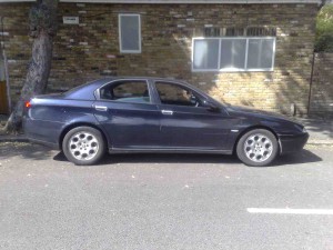
Complete digital workshop service and repair manual written for the Alfa Romeo 166; Production model years: 1998 1999 2000 2001 2002 2003 2004 2005 2006 2007. All styles covered (all models, and engines). This QUALITY manual is 100% COMPLETE and INTACT, no MISSING/CORRUPT pages/sections to freak you out! Buy from responsible seller and get INSTANT DOWNLOAD now without wasting your hard-owned money on uncertainty or surprise; this manual is exactly as described.

PRODUCT DETAILS:
Total Size: 680MB
File Format: ISO
Delivery: instant download link displayed on checkout page & emailed to you after payment
Protection: DRM-free; without any restriction
Printable: Yes

MAKE: Alfa Romeo
MODEL: 166 (2.0 TS, 2.0 TB, 2.5 V6, 3.0 V6, 2.4 JTD 10V, 3.2 V6, 2.4 JTD 20V)
YAER: 1998 1999 2000 2001 2002 2003 2004 2005 2006 2007
LANGUAGE: EN/DE/ES/FR/IT/NL/PT/PL

This COMPLETE official full workshop service repair manual includes:
* Detailed sub-steps expand on repair procedure information
* Notes, cautions and warnings throughout each chapter pinpoint critical information.
* Numbered instructions guide you through every repair procedure step by step.
* Bold figure number help you quickly match illustrations with instructions.
* Detailed illustrations, drawings and photos guide you through every procedure.
* Enlarged inset helps you identify and examine parts in detail.
* Numbered table of contents easy to use so that you can find the information you need fast.
* This manual also makes it easy to diagnose and repair problems with your machines electrical system.
* Troubleshooting and electrical service procedures are combined with detailed wiring diagrams for ease of use.

* COMPLETE, Absolutely No Missing Pages!
* Official Service INFORMATION You Can Count On!
* Customer Satisfaction GUARANTEED!

EXCERPT (1998-2007 Alfa Romeo 166 Service/Repair Manual):
1. Undo the bolts (1a) and remove the flanges on the differential (1b), complete with seals.
2. Remove the adjustment shim.
1. Undo the bolts (1a) and remove the support for the differential internal housing (1b).
2. Remove the differential.
3. Remove the differential bearing outer races.
4. Remove the magnet.
1. Remove the bolt for the Reverse gear shaft.
2. Undo the bolts (2a) and remove the gearbox casing (2b).
The gearbox casing is sealed to the bell housing: release the two parts using a wooden or resin hammer.
1. Unscrew bolts (1a) and (1b).
2. Remove the 5 th speed control rod (2a) from the Reverse gear selector fork (2b) and the 5 th speed selector (2c).
3. Remove the 5 th speed selector fork from the control rod.
1. At the same time, remove the main shaft, layshaft, reverse shaft and 1 st , 2 nd , 3 rd and 4 th speed selector fork assemblies.
Keep the units assembled until they are placed on the workbench.
Separate the selector forks from the rods.
1. Remove the clutch release bearing fork.
2. Remove the outer non-slip bush.
1. Undo the nut fixing the rear power unit rigid support to the flexible mounting.
2. Undo the bolts fixing the power unit rear flexible mounting to the front suspension frame.
3. Undo the bolts (3a) and remove the bracket (3b) connecting the power unit rigid rear support to the crankcase sump.
1. Undo the bolts (1a) and remove the power unit rigid rear support (1b) removing it through the wheel arch.
1820B08 Clutch release HYDRAULIC SYSTEM – Bleeding air and restoring level
1820B13 hose from clutch fluid reservoir to rigid intermediate pipe for master cylinder -r r with pedal unit removed for right hand drive versions
1820B15 hose from rigid intermediate pipe to master cylinder (pump) – r r with pedal unit removed for right hand drive versions
1820B17 pipe from inlet and outlet from master cylinder (pump) and hydraulic damper – r r with pedal unit removed for right hand drive versions
1820B20 (Pump) – MASTER CYLINDER R.R.
1820B21 (Pump) – MASTER CYLINER R.R. for right hand drive versions
1820B30 OPERATING CYLINDER/CLUTCH HYDRAULIC ACTUATOR – R.R.
1820B40 FLEXIBLE PIPE from clutch reservoir to (pump) – master cylinder R.R.
1820B46 RIGID supply PIPE from (pump) – master cylinder R.R .
1820B48 FLEXIBLE supply PIPE to operating cylinder -R.R.
1820B56 rigid pipe from vibration damper to slave cylinder – r r
1820B58 clutch hydraulic circuit vibration damper – r+r
1. Remove the two plastic buttons (1a) and remove soundproof protection (1b).
1. Disconnect the flexible hose from the clutch fluid reservoir to the intermediate rigid pipe for the master cylinder, rigid pipe side.
1. Working from the engine bay, disconnect the flexible hose from the clutch fluid reservoir to the intermediate rigid pipe for the master cylinder, reservoir side, and remove.
Remove the flexible hose from the clutch fluid reservoir to the intermediate rigid pipe for the master cylinder, taking it out of the engine compartment.
Refitting ( Removing )
Place the flexible hose from the clutch fluid reservoir to the intermediate rigid pipe for the master cylinder back in its housing and connect it.
Place the soundproof cover back in its housing and secure it using the plastic pins.


MAR1669807OMMK
Price: $12.99 USD

Posted on

1997-2007 Alfa Romeo 159 Workshop Repair & Service Manual (626M CD, Searchable, Printable)


MAR1590511OMMK
Price: $12.99 USD

1997-2007 Alfa Romeo 159 Workshop Repair & Service Manual (626M CD, Searchable, Printable)

Complete digital workshop service and repair manual written for the Alfa Romeo 159; Production model years: 1997 1998 1999 2000 2001 2002 2003 2004 2005 2006 2007. All styles covered (all models, and engines). This QUALITY manual is 100% COMPLETE and INTACT, no MISSING/CORRUPT pages/sections to freak you out! Buy from responsible seller and get INSTANT DOWNLOAD now without wasting your hard-owned money on uncertainty or surprise; this manual is exactly as described.

PRODUCT DETAILS:
Total Size: 626M
File Format: ISO
Delivery: instant download link displayed on checkout page & emailed to you after payment
Protection: DRM-free; without any restriction
Printable: Yes

MAKE: Alfa Romeo
MODEL: 159 (1.8, 1.9 JTS, 2.2 JTS, 3.2 JTS, 1.9 JTD 8V, 1.9 JTD 16V, 2.4 JTD 20V)
YAER: 2005 2006 2007 2008 2009 2010 2011
LANGUAGE: EN/DE/ES/FR/IT/NL/PT

This COMPLETE official full workshop service repair manual includes:
* Detailed sub-steps expand on repair procedure information
* Notes, cautions and warnings throughout each chapter pinpoint critical information.
* Numbered instructions guide you through every repair procedure step by step.
* Bold figure number help you quickly match illustrations with instructions.
* Detailed illustrations, drawings and photos guide you through every procedure.
* Enlarged inset helps you identify and examine parts in detail.
* Numbered table of contents easy to use so that you can find the information you need fast.
* This manual also makes it easy to diagnose and repair problems with your machines electrical system.
* Troubleshooting and electrical service procedures are combined with detailed wiring diagrams for ease of use.

* COMPLETE, Absolutely No Missing Pages!
* Official Service INFORMATION You Can Count On!
* Customer Satisfaction GUARANTEED!

EXCERPT (1997-2007 Alfa Romeo 159 Service/Repair Manual):
Removing ( Refitting )
– Position the vehicle on a lift.
– Make sure that the ignition key is in the OFF position, then disconnect the battery terminal (-).
– Battery
See A001 BATTERY
Op. 0010T84 COOLANT FOR AIR CONDITIONING SYSTEM – DEHYDRATE AND REPRESSURIZE.
Op. 7210A18 R.R FRONT CROSSMEMBER
– Using a suitable syringe, draw off the power assisted steering fluid from the reservoir.
Op. 4130B40 SUPPLY PIPE FROM PUMP TO POWER STEERING BOX – R.R.
1. Loosen the band and disconnect the supply pipe from the power assisted steering fluid reservoir to the pump, power assisted steering pump side.
2. Disconnect the rapid connector for the return pipe from the heat exchanger pipe to the power assisted steering fluid reservoir, heat exchanger side.
3. Undo the bolts (3a) and remove the power assisted steering fluid reservoir (3b) complete with pipes (3c).
4. Loosen the band and disconnect the coolant return pipe, cylinder head side.
1. Disconnect the rapid connector for the power assisted steering system heat exchanger inlet pipe, heat exchanger side.
2. Remove the heat exchanger pipe (2a) after having released it from the securing band (2b).
1. Undo the bolt (1a) and disconnect the inlet/outlet pipes from the air conditioning compressor (1b).
Seal the connectors that have been disconnected using suitable plugs to prevent dampness and impurities from entering the system.
2. Undo the nut (2a) and disconnect the air conditioning pipes intermediate flange (2b).
Seal the connectors that have been disconnected using suitable plugs to prevent dampness and impurities from entering the system.
3. Remove the air conditioning system pipes.
Op. 5530B10 BATTERY – R+R
1. Disconnect the electrical connections from the injection/ignition system control unit.
1. Engine management control unit
See M010 ENGINE MANAGEMENT ECU
2. Undo the bolts (2a) and remove the battery drip tray (2b) complete with injection/ignition system control unit (2c).
1. Open the junction unit cover, rotate the junction unit and disconnect the electrical connection (connector A).
Front/engine coupling
See D004 FRONT/ENGINE COUPLING
1. Loosen the band and disconnect the brake servo vacuum intake pipe, air chamber side.
1. Disconnect the rapid connector for the fuel vapour pipe intermediate coupling.
2. Disconnect the rapid connector for the fuel supply pipe, multiple connector side.
– Discharge the fuel supply system pressure.
1. Disconnect the electrical connection for the left upper Lambda sensor.
Lambda sensor on pre-catalyzer
See K015 LAMBDA SENSOR ON PRE-CATALYZER
2. Disconnect the electrical connection for the right upper Lambda sensor.
Lambda sensor on pre-catalyzer -2
See K016 LAMBDA SENSOR ON PRE-CATALYZER -2
3. Disconnect the electrical connection for the left rear Lambda sensor to the catalytic converter.
Lambda sensor on catalyser
See K017 LAMBDA SENSOR ON CATALYSER
4. Disconnect the electrical connection for the right rear Lambda sensor to the catalytic converter.
Lambda sensor on catalyser 2
See K018 LAMBDA SENSOR ON CATALYSER – 2
Mark the electrical connections for disconnect them so that they can be correctly refitted.
1. Disconnect the rapid connectors for the air conditioning system heater coolant inlet and outlet pipes.
1. Loosen the collar and disconnect the supply pipe from the engine coolant reservoir.
– Replace the brake-clutch fluid reservoir plug using the tool
Brake-clutch fluid reservoir cap
1. Release the retaining clip (1a) and disconnect the pipe (1b) between the damper and the clutch operating cylinder (1b), operating cylinder side.
2. Undo the bolt (2a) and disconnect the earth lead (2b) (connector B) from the gearbox.
Battery earth on engine
See C002 BATTERY EARTH ON ENGINE
1. Disconnect the electrical connection from the reversing light switch
Reversing lights switch
See I020 REVERSING LIGHTS SWITCH
1. Disconnect the gear selector cable.
2. Disconnect the gear engagement cable.
1. Unscrew the bolts (1a) and move aside the bracket (1b) complete with gear selection and engagement cables (1c).
Op. 4450B12 FRONT WHEELS (TWO) – R+R
Op. 1076B72 INTERMEDIATE EXHAUST PIPE WITH HOSE SECTION – R+R
1. Undo the bolts (1a) and move the brake calliper assemblies (1b) to the side and secure them appropriately.
1. Undo the nuts fixing the steering rods to the front steering knuckles.
2. Disconnect the steering rods (2a) from the front steering knuckle using the tool (2b).
Extracting steering rod from steering knuckle
1. Undo the nuts (1a) and disconnect the front suspension upper track control arms (1b) from the steering knuckles (1c).


MAR1590511OMMK
Price: $12.99 USD

Posted on

1997-2007 Alfa Romeo 156 Workshop Repair Service Manual BEST DOWNLOAD

1997-2007 Alfa Romeo 156 Workshop Repair Service Manual BEST DOWNLOAD

MAR1569707OMMK
Price: $12.99 USD

1997-2007 Alfa Romeo 156 Workshop Repair Service Manual BEST DOWNLOAD

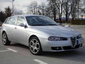
This highly detailed Manual for your 1997-2007 Alfa Romeo 156 contains everything you will ever need to repair, maintain, rebuild, refurbish or restore your vehicle. All diagnostic and repair procedures are covered in great detail.

This QUALITY manual is 100 percents COMPLETE and INTACT, no MISSING/CORRUPT pages/sections to freak you out! Buy from responsible seller and get INSTANT DOWNLOAD now without wasting your hard-owned money on uncertainty or surprise; this manual is exactly as described. This Digital Workshop Repair Manual for 1997-2007 Alfa Romeo 156 covers the same information that Professional Technicians and Mechanics have. You can view and print out the complete repair procedures with this easy to use this Digital Workshop Repair Manual for 1997-2007 Alfa Romeo 156 – you do not need to be skilled with a computer! Once you have found your information, just print it out and start work. No more messy manuals that you have to keep replacing or cant use any more due to wear and tear.

All Repair Procedures Covered From A-Z
High Quality Photos, Illustrations And Diagrams
Buy From A Trusted Seller, Selling Genuine Items

MAKE: Alfa Romeo
MODEL: 156 (2.4 JTD 20V, 2.4 JTD 10V, 2.0 JTS, 1.9 JTD 16V, 1.9 JTD 8V, 3.2 V6, 2.5 V6, 2.0 JTS, 1.8 TS, 1.6 TS, 2.0 TS)
YAER: 1997 1998 1999 2000 2001 2002 2003 2004 2005 2006 2007
LANGUAGE: EN/DE/ES/FR/IT/NL/PL/GK/PT/CZ/TR

SERVICE MANUAL DETAILS:
1. Downloadable: YES
2. Requirements: Windows
3. FileTYPE: ISO
4. Compatibility: All Versions of Windows

1997-2007 Alfa Romeo 156

TABLE OF CONTENT (example)

GENERAL INFORMATION *

ENGINE *
engine mechanical
engine lubrication system
engine cooling system
engine control system
fuel system
exhaust system

TRANSMISSION/TRANSAXLE *
clutch
manual transaxle
automatic transaxle

DRIVELINE/AXLE *
front axle
rear axle

SUSPENSION *
front suspension
rear suspension
road wheels & tyres

BRAKES *
brake system
parking brake system
brake control system

STEERING *
power steering system
steering system

RESTRAINTS *
seat belts
supplemental restraint system (srs)

BODY *
body, lock & security system
glasses, window system & mirrors
roof
exterior & Interior
Instrumental panel
seat

AIR CONDITIONER *
air conditioner system

ELECTRICAL *
wiring diagrams
starting & charging system
lighting system
driver information system
wiper, washer & horn
body control system
lan system
audio visual, navigation & telephone system
auto cruise control system
power supply, ground & circuit elements

MAINTENANCE *
maintenance

INDEX *
alphabetical Index


MAR1569707OMMK
Price: $12.99 USD