Posted on

2006 Chevrolet HHR Workshop Repair & Service Manual (5,863 Pages, Printable, iPad-ready PDF)

2006 Chevrolet HHR Workshop Repair & Service Manual (5,863 Pages, Printable, iPad-ready PDF)

Orbisius CyberStore: Product [341] was not found.

2006 Chevrolet HHR Workshop Repair & Service Manual (5,863 Pages, Printable, iPad-ready PDF)

Complete digital workshop service and repair manual written for the 2006 Chevrolet HHR. All styles covered (all models, and engines). It is in the cross-platform PDF document format so that it works like a charm on all kinds of devices.

This QUALITY manual is 100% COMPLETE and INTACT, no MISSING/CORRUPT pages/sections to freak you out! Buy from responsible seller and get INSTANT DOWNLOAD now without wasting your hard-owned money on uncertainty or surprise; this manual is exactly as described.

PRODUCT DETAILS:
Total Pages: 5,863 pages
File Format: PDF (Windows & Mac & Linux)
Language: English
Delivery: instant download link displayed on checkout page & emailed to you after payment
Protection: DRM-free; without any restriction
Printable: Yes

This COMPLETE full workshop service repair manual includes:
* Detailed sub-steps expand on repair procedure information
* Notes, cautions and warnings throughout each chapter pinpoint critical information.
* Numbered instructions guide you through every repair procedure step by step.
* Bold figure number help you quickly match illustrations with instructions.
* Detailed illustrations, drawings and photos guide you through every procedure.
* Enlarged inset helps you identify and examine parts in detail.
* Numbered table of contents easy to use so that you can find the information you need fast.
* This manual also makes it easy to diagnose and repair problems with your machines electrical system.
* Troubleshooting and electrical service procedures are combined with detailed wiring diagrams for ease of use.
* COMPLETE, Absolutely No Missing Pages!
* Customer Satisfaction GUARANTEED!

EXCERPT (2006 Chevrolet HHR Service/Repair Manual):
1. Install a scan tool.
2. Monitor the engine control module (ECM) for DTCs with a scan tool. If other DTCs are set, except DTC P0315, refer to Diagnostic Trouble Code (DTC) List- Vehicle for the applicable DTC that set.
3. With a scan tool, select the CKP system variation learn procedure within the Special Functions menu and perform the following:
1. Observe the fuel cut-off for the applicable engine.
2. Block the drive wheels.
3. Set the parking brake.
4. Place the vehicle’s transmission in Park or Neutral.
5. Turn the air conditioning (A/C) OFF.
6. Cycle the ignition from OFF to ON.
7. Apply and hold the brake pedal for the duration of the procedure.
8. Start and idle the engine.
9. Accelerate to wide open throttle (WOT). The engine should not accelerate beyond the calibrated fuel cut -off RPM value noted in step 3 .1. Release the throttle immediately if the value is exceeded.
IMPORTANT: While the learn procedure is in progress, release the throttle immediate! when the engine starts to decelerate. The engine control is returned to the operator and the engine responds to throttle position after the learn procedure is complete.
10. Release the throttle when fuel cut-off occurs.
4. The scan tool displays Learn Status: Learned this Ignition. If the scan tool indicates that DTC P0315 ran and passed, the CKP variation learn procedure is complete. If the scan tool indicates DTC P0315 failed or did not run, refer to DTC P0315 . If any other DTCs set, refer to Diagnostic Trouble Code (DTC) List- Vehicle for the applicable DTC that set.
5. Turn OFF the ignition for 30 seconds after the learn procedure is completed successfully.

1. Remove the throttle body. Refer to Throttle Body Assembly Replacement.
2. Disconnect the manifold absolute pressure (MAP) sensor electrical connector.
3. Remove the MAP sensor. IMPORTANT: If the MAP sensor seal is damaged, the MAP sensor must be replaced.
4. Inspect the seal for damage.

1. Install the NEW MAP sensor seal, if required.
2. Install the MAP sensor.
3. Connect the MAP sensor electrical connector.
4. Install the throttle body. Refer to Throttle Body Assembly Replacement.


Orbisius CyberStore: Product [341] was not found.
Posted on

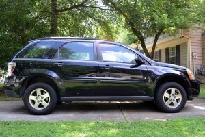
2005-2008 Chevrolet Equinox Workshop Repair & Service Manual (9,720 Pages, Printable, iPad-ready PDF)

2005-2008 Chevrolet Equinox Workshop Repair & Service Manual (9,720 Pages, Printable, iPad-ready PDF)

INSTANT DOWNLOAD


2005-2008 Chevrolet Equinox Workshop Repair & Service Manual (9,720 Pages, Printable, iPad-ready PDF)

Complete digital workshop service and repair manual written for the Chevrolet Equinox; Production model years: 2005 2006 2007 2008. All styles covered (all models, and engines). It is in the cross-platform PDF document format so that it works like a charm on all kinds of devices.

This QUALITY manual is 100% COMPLETE and INTACT, no MISSING/CORRUPT pages/sections to freak you out! Buy from responsible seller and get INSTANT DOWNLOAD now without wasting your hard-owned money on uncertainty or surprise; this manual is exactly as described.

PRODUCT DETAILS:
Total Pages: 9,720 pages
File Format: PDF (Windows & Mac & Linux)
Language: English
Delivery: instant download link displayed on checkout page & emailed to you after payment
Protection: DRM-free; without any restriction
Printable: Yes

This COMPLETE official full workshop service repair manual includes:
* Detailed sub-steps expand on repair procedure information
* Notes, cautions and warnings throughout each chapter pinpoint critical information.
* Numbered instructions guide you through every repair procedure step by step.
* Bold figure number help you quickly match illustrations with instructions.
* Detailed illustrations, drawings and photos guide you through every procedure.
* Enlarged inset helps you identify and examine parts in detail.
* Numbered table of contents easy to use so that you can find the information you need fast.
* This manual also makes it easy to diagnose and repair problems with your machines electrical system.
* Troubleshooting and electrical service procedures are combined with detailed wiring diagrams for ease of use.

* COMPLETE, Absolutely No Missing Pages!
* Official Service INFORMATION You Can Count On!
* Customer Satisfaction GUARANTEED!

EXCERPT (2005-2008 Chevrolet Equinox Service/Repair Manual):
SCAN TOOL DATA DEFINITIONS
Use the Scan Tool Data Display Values and Definitions Information in order to assist in diagnosing control module problems. Compare the vehicles actual scan tool data with the typical data display value table information. Use the data information in order to aid in understanding the nature of the problem when the vehicle does not match with the typical data display values.
The scan tool data values were taken from a known good vehicle under the following conditions:
• The ignition switch is in the ON position.
• The engine is running at idle.
• The vehicle is in PARK.
• The doors are closed.
• The windows are closed.
• The A/C is ON, in UPPER mode.
• The ambient air temperatures are at 22-27°C (70-80°F).
The HVAC Scan Tool Data Definitions contains a brief description of all HVAC related parameters available on the scan tool. The list is in alphabetical order. A given parameter may appear in any one of the data lists. In some cases, the parameter may appear more than once or in more than one data list in order to group certain related parameters together.
Temperature Description and Operation.
• The following could cause window fogging:
• Wet carpet or mats
• High humidity
• Interior water leak
• Blocked A/C evaporator drain tube
• Maximum passenger capacity
• Blocked body pressure relief valves
• Inspect the air distribution system for causes of reduced air flow:
• Obstructed or dirty passenger compartment air filter, if equipped
• Blocked or damaged air inlet or outlet vents
1. Remove the instrument panel compartment. Refer to Compartment Replacement – Instrument Panel (1/P) .
2. Disconnect the electrical connector from the air temperature actuator.
3. Remove the air temperature actuator screws from the HV AC module.
4. Remove the air temperature actuator from the HVAC module.
1. Remove the left side insulator/closeout panel. Refer to Closeout/Insulator Panel Replacement- Left.
2. Remove the communication interface module, if equipped. Refer to Communication Interface Module Replacement .
3. Disconnect the electrical connector from the mode actuator.
4. Remove the mode actuator screws from the evaporator case assembly.
5. Remove the mode actuator from the evaporator case assembly.


INSTANT DOWNLOAD


Posted on

2004-2010 Chevrolet Aveo Workshop Repair & Service Manual (8,275 Pages, Printable, Bookmarked, iPad-ready PDF)

2004-2010 Chevrolet Aveo Workshop Repair & Service Manual (8,275 Pages, Printable, iPad-ready PDF)

MCVLAV0410NPES
Price: $14.99 USD

2004-2010 Chevrolet Aveo Workshop Repair & Service Manual (8,275 Pages, Printable, iPad-ready PDF)

Complete digital workshop service and repair manual written for the Chevrolet Aveo; Production model years: 2004 2005 2006 2007 2008 2009 2010. All styles covered (all models, and engines). It is in the cross-platform PDF document format so that it works like a charm on all kinds of devices.

This QUALITY manual is 100% COMPLETE and INTACT, no MISSING/CORRUPT pages/sections to freak you out! Buy from responsible seller and get INSTANT DOWNLOAD now without wasting your hard-owned money on uncertainty or surprise; this manual is exactly as described.

PRODUCT DETAILS:
Total Pages: 8,275 pages
File Format: PDF (Windows & Mac & Linux)
Language: English
Delivery: instant download link displayed on checkout page & emailed to you after payment
Protection: DRM-free; without any restriction
Printable: Yes

This COMPLETE official full workshop service repair manual includes:
* Detailed sub-steps expand on repair procedure information
* Notes, cautions and warnings throughout each chapter pinpoint critical information.
* Numbered instructions guide you through every repair procedure step by step.
* Bold figure number help you quickly match illustrations with instructions.
* Detailed illustrations, drawings and photos guide you through every procedure.
* Enlarged inset helps you identify and examine parts in detail.
* Numbered table of contents easy to use so that you can find the information you need fast.
* This manual also makes it easy to diagnose and repair problems with your machines electrical system.
* Troubleshooting and electrical service procedures are combined with detailed wiring diagrams for ease of use.

* COMPLETE, Absolutely No Missing Pages!
* Official Service INFORMATION You Can Count On!
* Customer Satisfaction GUARANTEED!

EXCERPT (2004-2010 Chevrolet Aveo Service/Repair Manual):
DIAGNOSTIC STARTING POINT- ENGINE MECHANICAL
Begin the system diagnosis by reviewing the Symptoms-Engine Mechanical Symptoms-Engine Mechanical. Reviewing the description and operation information will help you determine the correct symptom diagnostic procedure when a malfunction exists. Reviewing the description and operation information will also help you determine if the condition described by the customer is normal operation. Refer to Engine Component Description in order to identify the correct procedure for diagnosing the system and where the procedure is located.
SYMPTOMS -ENGINE MECHANICAL
Strategy Based Diagnostics
1. Perform the Diagnostic System Check – Engine Controls in Engine Controls – 1.2L before using the symptom tables, if applicable.
2. Review the system operations in order to familiarise yourself with the system functions. Refer to Disassembled Views and Engine Component Description and Lubrication Description.
All diagnosis on a vehicle should follow a logical process. Strategy based diagnostics is a uniform approach for repairing all systems. The diagnostic flow may always be used in order to resolve a system condition. The diagnostic flow is the place to start when repairs are necessary.
Visual/Physical Inspection
• Inspect for aftermarket devices which could affect the operation of the engine.
• Inspect the easily accessible or visible system components for obvious damage or conditions which could cause the symptom.
• Check for the correct oil level, proper oil viscosity, and correct filter application.
• Verify the exact operating conditions under which the concern exists. Note factors such as engine RPM, ambient temperature, engine temperature, amount of engine warm-up time, and other specifics.
• Compare the engine sounds, if applicable, to a known good engine and make sure you are not trying to correct a normal condition.
Intermittent
Test the vehicle under the same conditions that the customer reported in order to verify the system is operating properly.

1. Remove the fuel pump fuse.
2. Start the engine. After it stalls, crank the engine for 10 seconds to rid the fuel system of fuel pressure.
CAUTION: Refer to Battery Disconnect Caution in Cautions and Notices.
3. Disconnect the negative battery cable.
4. Remove the air filter housing.
5. Remove the fuel rail. Refer to Fuel Rail Assembly Replacement in Engine Controls – 1.2L.
6. Disconnect the A/C pressure sensor connector.
7. Disconnect the power steering pump pressure sensor connector.
8. Disconnect the throttle cable bracket with the bolt.
9. Disconnect the manifold absolute pressure (MAP) sensor connector.
10. Remove the brake booster vacuum hose at the intake manifold.
11. Remove the exhaust gas recirculation (EGR) pipe and valve.
12. Remove the engine wiring harness from the intake manifold.
13. Remove the intake manifold retaining bolts and the nuts in the sequence shown.
14. Remove the intake manifold.
15. Remove the intake manifold gasket.
16. Remove the intake manifold subsidiary bracket bolts.
17. Remove the intake manifold subsidiary bracket.


MCVLAV0410NPES
Price: $14.99 USD

Posted on

1995-2005 Chevrolet Astro Workshop Repair & Service Manual in Spanish (Searchable, Printable, Bookmarked, iPad-ready PDF)

1995-2005 Chevrolet Astro Workshop Repair & Service Manual in Spanish (Searchable, Printable, Bookmarked, iPad-ready PDF)

1995-2005 Chevrolet Astro Workshop Repair & Service Manual in Spanish (Searchable, Printable, Bookmarked, iPad-ready PDF)


MCVLASTR9505OPSK
Price: $9.99 USD

Complete digital workshop service and repair manual written for the Chevrolet Astro; Production model years: 1995 1996 1997 1998 1999 2000 2001 2002 2003 2004 2005. All styles covered (all models, and engines). It is in the cross-platform PDF document format so that it works like a charm on all kinds of devices.

This QUALITY manual is 100% COMPLETE and INTACT, no MISSING/CORRUPT pages/sections to freak you out! Buy from responsible seller and get INSTANT DOWNLOAD now without wasting your hard-owned money on uncertainty or surprise; this manual is exactly as described.

PRODUCT DETAILS:
Total Pages: 3,291 pages
File Format: PDF (Windows & Mac & Linux)
Language: Spanish
Delivery: instant download link displayed on checkout page & emailed to you after payment
Protection: DRM-free; without any restriction
Printable: Yes

This COMPLETE official full workshop service repair manual includes:
* Detailed sub-steps expand on repair procedure information
* Notes, cautions and warnings throughout each chapter pinpoint critical information.
* Numbered instructions guide you through every repair procedure step by step.
* Bold figure number help you quickly match illustrations with instructions.
* Detailed illustrations, drawings and photos guide you through every procedure.
* Enlarged inset helps you identify and examine parts in detail.
* Numbered table of contents easy to use so that you can find the information you need fast.
* This manual also makes it easy to diagnose and repair problems with your machines electrical system.
* Troubleshooting and electrical service procedures are combined with detailed wiring diagrams for ease of use.

* COMPLETE, Absolutely No Missing Pages!
* Official Service INFORMATION You Can Count On!
* Customer Satisfaction GUARANTEED!

EXCERPT (1995-2005 Chevrolet Astro Service/Repair Manual):
1. Los tubos de freno, apretando las conexiones manualmente en el cilindro principal y en la unidad hidráulica (2/3).
– Las conexiones de los tubos de freno: 11,5 N.m (8,5 lbf.pie).
– Alinee los tubos de freno, asegurándose de que los mismos estén paralelos para que no haya interferencia entre ellos y ni tampoco con los otros componentes.
2. Las abrazaderas de fijación (1) en los tubos rígidos de freno.
3. La caja de relevadores en el soporte.
4. El mazo de conductores en el soporte de la caja de relevadores.
5. Los conectores múltiples en el soporte de la caja de relevadores.
6. La batería en el vehículo.

Tubo de Freno de la Unidad Hidráulica del ABS a la Manguera (Flexible) de la Rueda Delantera Izquierda (Freno de Servicio) – Quitar e Instalar
Grupo H – 5 de 6 10/2002 Astra
1. El tubo de freno de la rueda delantera izquierda, fijándolo en los soportes y hebillas alrededor de la carrocería del vehículo.
2. La conexión del tubo de freno de la rueda delantera izquierda en la manguera flexible del freno delantero. – La conexión del tubo de freno a la manguera de la rueda: 11,5 N.m (8,5 lbf.pie).
3. El tubo de freno (2) de la rueda delantera izquierda en la unidad hidráulica, apretando la conexión manualmente. – Alinee el tubo de freno, asegurándose de que estén perfectamente alineados y paralelos para evitar fricción con el otro tubo y los demás componentes.
– La conexión del tubo de freno a la unidad hidráulica: 11,5 N.m (8,5 lbf.pie).
4. La abrazadera de fijación (1) en los tubos de freno.
5. La caja de relevadores en el soporte.
6. El mazo de conductores en el soporte de la caja de relevadores.
7. Los conectores múltiples en los soportes de la caja de relevadores.

Tubo de Freno de la Unidad Hidráulica del ABS a la Manguera (Flexible) de la Rueda Delantera Derecha (Freno de Servicio) – Quitar e Instalar Grupo H – 3 de 6 10/2002 Astra
3. La caja de relevadores (3) del soporte de la caja de relevadores y desplácela hacia el lado.
4. El mazo de conductores del soporte de la caja de relevadores.
5. La tapa del depósito de fluido de freno y quite el fluido de freno.
6. La abrazadera de fijación (1) de los tubos de freno.
7. El tubo de freno de la rueda delantera derecha (2) de la unidad hidráulica.
– Proteja las conexiones abiertas de la unidad hidráulica para evitar contaminación; utilice tapones selladores.
– Levante el vehículo.


MCVLASTR9505OPSK
Price: $9.99 USD

Posted on

2002-2004 Cadillac Escalade Workshop Repair & Service Manual (9,610 Pages, Printable, iPad-ready PDF)

2002-2004 Cadillac Escalade Workshop Repair & Service Manual (9,610 Pages, Printable, iPad-ready PDF)

MCDLESCL0204NPEK
Price: $14.99 USD

2002-2004 Cadillac Escalade Workshop Repair & Service Manual (9,610 Pages, Printable, iPad-ready PDF)

Complete digital workshop service and repair manual written for the 2002-2004 Cadillac Escalade; Production model years: 2002 2003 2004. All styles covered (all models, and engines). It is in the cross-platform PDF document format so that it works like a charm on all kinds of devices.

This QUALITY manual is 100% COMPLETE and INTACT, no MISSING/CORRUPT pages/sections to freak you out! Buy from responsible seller and get INSTANT DOWNLOAD now without wasting your hard-owned money on uncertainty or surprise; this manual is exactly as described.

PRODUCT DETAILS:
Total Pages: 9,610 pages
File Format: PDF (Windows & Mac & Linux)
Language: English
Delivery: instant download link displayed on checkout page & emailed to you after payment
Protection: DRM-free; without any restriction
Printable: Yes

This COMPLETE full workshop service repair manual includes:
* Detailed sub-steps expand on repair procedure information
* Notes, cautions and warnings throughout each chapter pinpoint critical information.
* Numbered instructions guide you through every repair procedure step by step.
* Bold figure number help you quickly match illustrations with instructions.
* Detailed illustrations, drawings and photos guide you through every procedure.
* Enlarged inset helps you identify and examine parts in detail.
* Numbered table of contents easy to use so that you can find the information you need fast.
* This manual also makes it easy to diagnose and repair problems with your machines electrical system.
* Troubleshooting and electrical service procedures are combined with detailed wiring diagrams for ease of use.

* COMPLETE, Absolutely No Missing Pages!
* Customer Satisfaction GUARANTEED!

EXCERPT (2002-2004 Cadillac Escalade Service/Repair Manual):
MOLDING REPLACEMENT – FRONT BUMPER CAP
Removal Procedure
1. Open the hood.
2. Remove the upper air baffle. Refer to Radiator Air Baffle and Deflector Replacement – Upper in Engine Cooling.
3. Remove the front grille. Refer to Grille Replacement (Cadillac) or Grille Replacement (Avalanche) or Grille Replacement (Chevrolet) or Grille Replacement (GMC) in Exterior Trim.
4. Remove the front bumper. Refer to Bumper Replacement – Front (Old Style) .
5. Remove the front bumper fascia cap by depressing all the tabs and pulling up.
Installation Procedure
1. Position the fascia cap tabs to the slots in the bumper.
2. Install the front bumper cap to the bumper pressing into place until fully seated.
3. Install the front bumper. Refer to Bumper Replacement – Front (Old Style) .
4. Install the front grille. Refer to Grille Replacement (Cadillac) or Grille Replacement (Avalanche) or Grille Replacement (Chevrolet) or Grille Replacement (GMC) in Exterior Trim.
5. Install the upper air baffle. Refer to Radiator Air Baffle and Deflector Replacement – Upper in Engine Cooling.
6. Close the hood.

Installation Procedure
1. Install the fog lamps, if equipped. Refer to Fog Lamp Replacement – Front in Lighting Systems.
2. Install the air deflector to the bumper if necessary. Refer to Air Deflector Replacement – Front Bumper Fascia.
3. Position the front bumper assembly on the vehicle.
MPORTANT: Tighten the bolts in the following sequence.
4. Install the retaining bolts (1, 2) to the front bumper.
Tighten:
1. Tighten the bracket bolt (1) to 85 N.m (63 lb ft).
2. Tighten the bracket bolt (2) to 85 N.m (63 lb ft).
3. Tighten the brace bolt to 55 N.m (41 lb ft).
5. Connect the electrical connector to the fog lamps, if equipped.
6. Install the front grille Refer to Grille Replacement (Cadillac) or Grille Replacement (Avalanche) or Grille Replacement (Chevrolet) or Grille Replacement (GMC) in Exterior Trim.


MCDLESCL0204NPEK
Price: $14.99 USD