Posted on

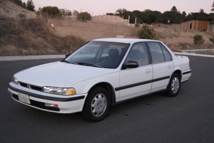
1986-2002 Honda Accord Repair & Service Manual (Printable PDF, 1.42GB)

Honda Accord 1986-2002

1986-2002 Honda Accord Repair & Service Manual (Printable PDF, 1.42GB)


INSTANT DOWNLOAD


Honda Accord 1986-2002 SAMPLE

Complete digital official shop manual contains service, maintenance, and troubleshooting information for the 1986-2002 Honda Accord. Diagnostic and repair procedures are covered in great detail to repair, maintain, rebuild, refurbish or restore your vehicle like a professional mechanic in local service/repair workshop. This cost-effective quality manual is 100% complete and intact as should be without any missing pages. It is the same factory shop manual used by dealers that guaranteed to be fully functional to save your precious time.

This manual for 1986-2002 Honda Accord is divided into different sections. Each section covers a specific component or system and, in addition to the standard service procedures, includes disassembling, inspecting, and assembling instructions. A table of contents is placed at the beginning of each section. Pages are easily found by category, and each page is expandable for great detail. It is in the cross-platform PDF document format so that it works like a charm on all kinds of devices. You do not need to be skilled with a computer to use the manual.

Buy the best manual on the Internet from responsible merchant and get instant download without surprise.

MAKE: Honda
YEAR: 1986 1987 1988 1989 1990 1991 1992 1993 1994 1995 1996 1997 1998 1999 2000 2001 2002
MODEL:

“’86.pdf”
835 pages
CA4: Accord 1600; CA5: Accord 2000
Transmission Group:
3: 5-speed (30)
4: Automatic (30)
5: 5-speed (40)
6: Automatic (401

“’86 Supplement.pdf”
177 pages

“’87 Supplement.pdf”
242 pages

“’88 Supplement.pdf”
340 pages

“’89 Supplement.pdf”
116 pages

“’90-’93 Aero Deck.pdf”
1,925 pages
1991 Accord Shop Manual
1991 Accord Aero Deck Shop Manual
1992 Accord & Accord Aero Deck Shop Manual
1992 Accord Coupe Shop Manual
1993 Accord & Accord Aero Deck Shop Manual

“’90.pdf”
1,020 pages

“’91 Aero Deck Supplement.pdf”
89 pages

“’91 Supplement.pdf”
166 pages

“’92 Aero Deck Supplement.pdf”
414 pages

“’92 Supplement.pdf”
152 pages

“’93 Aero Deck Supplement.pdf”
90 pages

“’93-’96 4D”
Accord 4D, Accord 4D Diesel
120MB PDF

“’94 Aero Deck Supplement.pdf”
234 pages

“’94 Coupe.pdf”
1,379 pages

“’94 Supplement.pdf”
315 pages

“’94 Wiring.pdf”
50 pages

“’94-’95 Supplement.pdf”
66 pages

“’94-’97 Coupe_AD”
Accord Coupe/(Aerodeck)AD Wagon
98MB PDF

“’95 Coupe.pdf”
1,378 page

“’96 Aero Deck_Coupe Supplement.pdf”
280 pages

“’96 Diesel Supplement.pdf”
230 pages

“’96 Supplement.pdf”
380 pages

“’96 Supplement alternate.pdf”
146 pages

“’96-’97 Supplement.pdf”
72 pages

“’97 Aero Deck_Coupe Supplement.pdf”
58 pages

“’98-’00”
440 MB, EXE format

“’98-’02 ETM”
1998-2002 Honda Accord Electrical Troubleshooting Manual
“Index.pdf” = the Table of Contents
31.6 MB PDF

“’98-’02.pdf”
2,520 pages
1998-2002 Accord (2Door/4Door, V6 Engine included) Factory Service Manual
Body (Chassis) Codes: CF8 CG3 CG5 CG6
Includes J30A V6 engine
Electrical Troubleshooting Manual

“’99”
297 MB, HTML format

“’99 alternate”
388 MB, EXE format

INSTANT Delivery: A download link will be sent to you instantly after payment. Simply click on the link and save it to your computer. You can use this Manual as long as you wish with no restrictions.

PRINTABLE with Diagrams: Just print the manual out and start to work. You can also use the manual with your laptop in your garage.

Customer SATISFACTION: If there is any problem, just drop a quick email. Within hours the issue shall be taken care of.

REFUND Policy: We sell high quality products only. In case there is any problem with your purchase, a replacement link will be sent to you. If we are at fault, you get 100% refund.

EXCERPT:
General Information
Chassis and Paint Codes
1998 Model… …. …. …….. …… … …… …… 1-2
Chassis and Paint Codes
1999 Model …………………………………. 1-3
Chassis and Paint Codes
2000 Model …………………………………. 1-4
Chassis and Paint Codes
2001 Model …………………………………. 1-5
Chassis and Paint Codes
2002 Model …………………………………. 1-6
Identification Number Locations …….. 1-7
Warning/Caution Label Locations 1-8
Under-hood Emission
Control Label ………………………………. 1-12
Lift and Support Points …………………… 1-17
Towing ………………………………………….. 1-18
Parts Marking .. ……………. ….. ….. ….. …… 1-19
Revised Component Terms …………….. 1-20

Transmission End Cover
End Cover and Idler Gears Installation
Special Tools Required
Mainshaft holder 07GAB-PF50101 or 07GAB-PF50100
1. Install the park lever (A) and park lever stop (B) on the control shaft (C), then install the lock bolt (D) with a new lock washer (E). Do not bend the lock tab of the lock washer in this step; bend it after check the park pawl engagement in step 25.
2. Coat the following parts with ATF:
• Splines of the countershaft, park gear, and old
locknut.
• Threads of the countershaft and old locknut.
• Old conical spring washer.
3. Install the park gear (A) using the old locknut (B) and a collar (C). Engage the park pawl (D) to the park gear, then tighten the old locknut until the shaft splines come out slightly over the park gear splines.
NOTE: Do not use an impact wrench.
4. Remove the locknut and the collar, then install only the bearing hub/bearing assembly (A) and old conical spring washer (B). Tighten the old locknut
(C) to seat the park gear to 226 N·m, then remove the locknut and conical spring washer.
NOTE: Do not use an impact wrench. Always use a
torque wrench to tighten the locknut.

INSTANT DOWNLOAD


Posted on

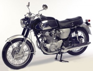
1965-1987 Honda 450-500 Motorcycle Repair & Service Manual (133 MB, Searchable & Printable PDF)

1965-1987 Honda 450-500 Motorcycle Repair & Service Manual

1965-1987 Honda 450-500 Motorcycle Repair & Service Manual (133 MB, Searchable & Printable PDF)


MHD450500OPEK.PDF
Price: $19.99 USD

’68-’75 CB450, CL450 SAMPLE

Complete digital official shop manual contains service, maintenance, and troubleshooting information for the 1965-1987 Honda 450-500 Motorcycle (450cc & 500cc). Diagnostic and repair procedures are covered in great detail to repair, maintain, rebuild, refurbish or restore your vehicle like a professional mechanic in local service/repair workshop. This cost-effective quality manual is 100% complete and intact as should be without any missing pages. It is the same factory shop manual used by dealers that guaranteed to be fully functional to save your precious time.

This manual is divided into different sections. Each section covers a specific component or system and, in addition to the standard service procedures, includes disassembling, inspecting, and assembling instructions. A table of contents is placed at the beginning of each section. Pages are easily found by category, and each page is expandable for great detail. It is in the cross-platform PDF document format so that it works like a charm on all kinds of devices. You do not need to be skilled with a computer to use the manual.

Buy the best manual on the Internet from responsible merchant and get instant download without surprise.

MAKE: Honda
YEAR: 1965 1966 1967 1968 1969 1970 1972 1973 1974 1975 1976 1977 1978 1979 1980 1981 1982 1983 1984 1985 1986 1987
MODEL:
“’65-’77 450cc & 500cc TWINS.pdf”
176 pages

“’68-’75 CB450, CL450.pdf”
246 pages

“’78-’87 450cc & 500cc Twins.pdf”
439 pages

INSTANT Delivery: A download link will be sent to you instantly after payment. Simply click on the link and save it to your computer. You can use this Manual as long as you wish with no restrictions.

PRINTABLE with Diagrams: Just print the manual out and start to work. You can also use the manual with your laptop in your garage.

Customer SATISFACTION: If there is any problem, just drop a quick email. Within hours the issue shall be taken care of.

REFUND Policy: We sell high quality products only. In case there is any problem with your purchase, a replacement link will be sent to you. If we are at fault, you get 100% refund.

EXCERPT:

A. Construction
It is no exaggeration to state that the quality of the engine reflects the superiority of the motorcycle.
An engine that is light in weight, compact, and having a large power output is a desirable attribute, however, the engine must have a well balanced appearance which matches the frame, in order to produce a perfect motorcycle.
This model was designed to fulfill this aim by employing many new ideas and the latest in technology.
The fruit of the effort is reflected in the motorcycle of high performance and a beautiful piece of machinery much sought after by avid riding fans.
Features such as the twin cylinder double overhead cam, torsion bar valve springs (which eliminates surging during high speed, and a regulating mechanism featured with an eccentric cam follower shaft which practically eliminates tappet adjustment, are typical of the revolutionary features of this motorcycle.
Also, the system of seven guide rollers suppresses the chain noise to the level which is unnoticeable; extra heavy duty bearings at the crankshaft and the transmission, and the dual oil filtering system incorporating both the centrifugal and the filtering mesh to enhance the durability and the long economical life of the engine. The two variable Venturi system of the CV carburetors assures uniform fuel mixture independently to the respective cylinders to provide smooth power output at all speed ranges. We are proud of the engine’s responsive acceleration and its high fuel economy.


MHD450500OPEK.PDF
Price: $19.99 USD

Posted on

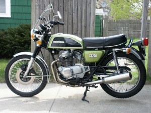
1968-1977 Honda 200-250-350-360 Motorcycle Repair & Service Manual (209 MB Searchable & Printable PDF)

1968-1977 Honda 200-250-350-360 Motorcycle Repair & Service Manual

1968-1977 Honda 200-250-350-360 Motorcycle Repair & Service Manual (209 MB Searchable & Printable PDF)


MHD200360OPEK.PDF
Price: $19.99 USD

’68-’73 250-350 SAMPLE

Complete digital official shop manual contains service, maintenance, and troubleshooting information for the 1968-1977 Honda 200-250-350-360 Motorcycle. Diagnostic and repair procedures are covered in great detail to repair, maintain, rebuild, refurbish or restore your vehicle like a professional mechanic in local service/repair workshop. This cost-effective quality manual is 100% complete and intact as should be without any missing pages. It is the same factory shop manual used by dealers that guaranteed to be fully functional to save your precious time.

This manual for 1968-1977 Honda 200-250-350-360 Motorcycle is divided into different sections. Each section covers a specific component or system and, in addition to the standard service procedures, includes disassembling, inspecting, and assembling instructions. A table of contents is placed at the beginning of each section. Pages are easily found by category, and each page is expandable for great detail. It is in the cross-platform PDF document format so that it works like a charm on all kinds of devices. You do not need to be skilled with a computer to use the manual.

Buy the best manual on the Internet from responsible merchant and get instant download without surprise.

MAKE: Honda
YEAR: 1968 1969 1970 1971 1972 1973 1974 1975 1976 1977
MODEL:

“’68-’73 250-350.pdf”
250-350 Model Shop Manual (CB250, CL250, CB350, CL350, SL350)
219 pages

“’68-’76 CB250, CB350, CL250, CL350, SL350.pdf”
250-350 Model Shop Manual (CB250, CL250, CB350, CL350, SL350)
359 pages
6228604; A3900908

“’73-’76 CB200, CL200.pdf”
CB200, CL200 Shop Manual
98 pages

“’74-’77 CB250-360, CL360_K1, CJ250T_360T.pdf”
CB250, CB360, CL360, CL360K1, CJ250T, CJ360T Shop Manual
173 pages

INSTANT Delivery: A download link will be sent to you instantly after payment. Simply click on the link and save it to your computer. You can use this Manual as long as you wish with no restrictions.

PRINTABLE with Diagrams: Just print the manual out and start to work. You can also use the manual with your laptop in your garage.

Customer SATISFACTION: If there is any problem, just drop a quick email. Within hours the issue shall be taken care of.

REFUND Policy: We sell high quality products only. In case there is any problem with your purchase, a replacement link will be sent to you. If we are at fault, you get 100% refund.

EXCERPT:
l. CAMSHAFT AND VALVE MECHANISM
Cylinder head
The cylinder head is so designed that the rocker arm shafts and rocker arms are incorporated into the cylinder head cover.
It can be removed or installed with the engine mounted on the frame to enable the cylinder and pistons to be replaced easily.
Valve guides
Each valve guide is securely supported by the spring seats as shown at right. It is also provided with the stem seals to prevent oil from leaking into the combustion chamber.
When disassembling the valve guide, take care not to compress the valve compressor (Tool No. 07957-3290000) more than necessary; otherwise the stem seals may be damaged.
Cylinder
The cylinder is an aluminum die casting which is light-weight and has great cooling efficiency. Two special cast iron sleeves are pressed into the cylinder.
Eight stud bolt holes are provided in the cylinder and the two holes at the rear outside act as oil passages to the cylinder head.
Pistons
The pistons are made of aluminum alloy. They are three-stage tapered as shown to provide for unequal expansion that occurs at operating temperature.
Piston pins
Each piston pin is full floating in both the connecting rod and piston with snap rings in both piston bosses. It is 1 mm offset (0.039 in.) to the intake side with respect to the center of the piston. The reason for this is that since the pressure on the piston on the explosion stroke rises to the maximum after the top dead center position, the side thrust on the piston is moved before the top dead center position to avoid rapid movement of the side thrust on the explosion stroke, preventing the piston from slapping the cylinder sleeve. The head of each piston is marked to make it easier to install it correctly.
2. CAM CHAIN TENSIONER MECHANISM
1. The cam chain tensioner is made of spring steel on which heat-resistant rubber is lined by paking and then heat-resistant teflon having less frictional resistance is coated, minimizing chain noise and improving durability.
2. The chain tension can be easily adjusted by loosening the adjusting bolt and then retightening it.
Cam chain slipper
1. The cam chain slipper installed to the cylinder block prevents chain vibrations often developed due to temporarily disturbed engine speed during deceleration.
2. The cam chain slipper is so constructed that the synthetic rubber is attached to the steel plate and it has great durability.


MHD200360OPEK.PDF
Price: $19.99 USD

Posted on

1959-1988 Honda 90/100/125/150/160/175 Model Motorcycle Repair & Service Manual (125 MB Searchable & Printable PDF)

1959-1988 Honda 90/100/125/150/160/175 Model Motorcycle Repair & Service Manual (125 MB Searchable & Printable PDF)

1959-1988 Honda 90/100/125/150/160/175 Model Motorcycle Repair & Service Manual (125 MB Searchable & Printable PDF)


MHD90175OPEK.PDF
Price: $19.99 USD

Honda 100-125 Series SAMPLE

Complete digital official shop manual contains service, maintenance, and troubleshooting information for the 1959-1988 Honda 90/100/125/150/160/175 Model Motorcycle. Diagnostic and repair procedures are covered in great detail to repair, maintain, rebuild, refurbish or restore your vehicle like a professional mechanic in local service/repair workshop. This cost-effective quality manual is 100% complete and intact as should be without any missing pages. It is the same factory shop manual used by dealers that guaranteed to be fully functional to save your precious time.

This manual for 1959-1988 Honda 90-175 Model Motorcycle is divided into different sections. Each section covers a specific component or system and, in addition to the standard service procedures, includes disassembling, inspecting, and assembling instructions. A table of contents is placed at the beginning of each section. Pages are easily found by category, and each page is expandable for great detail. It is in the cross-platform PDF document format so that it works like a charm on all kinds of devices. You do not need to be skilled with a computer to use the manual.

Buy the best manual on the Internet from responsible merchant and get instant download without surprise.

MAKE: Honda
YEAR: 1959 1960 1961 1962 1963 1964 1965 1966 1967 1968 1969 1970 1971 1972 1973 1974 1975 1976 1977 1978 1979 1980 1981 1982 1983 1984 1985 1986 1987 1988

MODEL:
“’59-’66 125-150 Series.pdf”
125-150 (C92, CS92, CB92, C95, CA95) Shop Manual
174 pages

“’64-’79 90 Series.pdf”
S90, CL90L, C90, CL90, CD90, CT90 Shop Manual
180 pages

“’65-’75 CB125, CB160.pdf”
CB125, CB160 Shop Manual
139 pages

“’69-’85 CB125, CB175, CL125, CL175.pdf”
CB125, CB175, CL125, CL175 Shop Manual
208 pages

“’69-’88 100-125 Series.pdf”
100-125 Model (CB100, CL100, SL100, CB125S, CD125S, SL125, TL125) Shop Manual
101 pages

INSTANT Delivery: A download link will be sent to you instantly after payment. Simply click on the link and save it to your computer. You can use this Manual as long as you wish with no restrictions.

PRINTABLE with Diagrams: Just print the manual out and start to work. You can also use the manual with your laptop in your garage.

Customer SATISFACTION: If there is any problem, just drop a quick email. Within hours the issue shall be taken care of.

REFUND Policy: We sell high quality products only. In case there is any problem with your purchase, a replacement link will be sent to you. If we are at fault, you get 100% refund.

EXCERPT:

II. MAINTENANCE OPERATIONS
1. TAPPET ADJUSTMENT
The inspection and adjustment must be performed while the engine is cold.
I) Unscrew the two 8mm seat mounting bolts and remove the seat.
2) Remove the fuel tank.
3) Unscrew and remove the tappet hole caps.
4) Remove the dynamo cover.
5) Turn the crankshaft so that the “T’ (timing) mark aligns with index mark on the stator and the piston is in the compression stroke. The piston in the compression
stroke can be determined by feeling rocker arms for clearance. (Fig. I)
6) Check tappet clearances with a thickness gauge and if it is necessary to adjust, loosen the lock nut and adjust the tappet adjust screw. (Fig. 2)
Tappet clearances:
Intake O.O5mm (0.002 in.)
Exhaust O.O5mm (0.002 in.)
When tightening the lock nut, exercise care so that the tappet clearance will not be disturbed. Recheck the tappet clearance.
2. CARBURETOR ADJUSTMENT
Warm up the engine before setting the engine idle speed and make the idle adjustment with the pilot air screw and throttle stop screw.
(Fig. 3)
1) Adjust the throttle stop screw to give idle speed of 1,200 rpm. Use a tachometer when it is available.
2) Turn the pilot air screw in and out to locate the position where engine rpm is highest.
Turning the screw in will provide a rich fuel mixture, turning the screw out will give a lean fuel mixture.
3) If engine rpm has increased by the adjustment of air screw, the engine rpm
should be set to the proper idle speed by using the throttle stop screw .
4) Turn the pilot air screw in or out within the range of 1/8 to 1/4 turn to obtain the optimum idling condition.


MHD90175OPEK.PDF
Price: $19.99 USD

Posted on

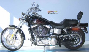
1991-2009 Harley Davidson DYNA Repair & Service Manual (315 MB, Searchable & Printable PDF)

1991-2009 Harley Davidson DYNA Repair & Service Manual

1991-2009 Harley Davidson DYNA Repair & Service Manual (315 MB, Searchable & Printable PDF)


MHDDYNA9109OPES.PDF
Price: $29.99 USD

’08 DYNA models SAMPLE

Complete digital official shop manual contains service, maintenance, and troubleshooting information for the Harley Davidson DYNA 1991-2009 Motorcycle. Diagnostic and repair procedures are covered in great detail to repair, maintain, rebuild, refurbish or restore your vehicle like a professional mechanic in local service/repair workshop. This cost-effective quality manual is 100% complete and intact as should be without any missing pages. It is the same factory shop manual used by dealers that guaranteed to be fully functional to save your precious time.

This manual for 1991-2009 Harley Davidson DYNA bike is divided into different sections. Each section covers a specific component or system and, in addition to the standard service procedures, includes disassembling, inspecting, and assembling instructions. A table of contents is placed at the beginning of each section. Pages are easily found by category, and each page is expandable for great detail. It is in the cross-platform PDF document format so that it works like a charm on all kinds of devices. You do not need to be skilled with a computer to use the manual.

Buy the best manual on the Internet from responsible merchant and get instant download without surprise.

MAKE: Harley Davidson
YEAR: 1991 1992 1993 1994 1995 1996 1997 1998 1999 2000 2001 2002 2003 2004 2005 2006 2007 2008 2009
MODEL:

“’08 DYNA models.pdf”
2008 Dyna Models Service Manual
99481-08
1,032 pages

“’09 DYNA models.pdf”
2009 Dyna Models Service Manual
99481-09
576 pages

“’91-’98 DYNA Glide.pdf”
1991-1998 DYNA EVOLUTION Service Manual
545 pages

“’99-’05 DYNA Glide.pdf”
1991-1998 FXD DYNA Service Manual
596 pages

INSTANT Delivery: A download link will be sent to you instantly after payment. Simply click on the link and save it to your computer. You can use this Manual as long as you wish with no restrictions.

PRINTABLE with Diagrams: Just print the manual out and start to work. You can also use the manual with your laptop in your garage.

Customer SATISFACTION: If there is any problem, just drop a quick email. Within hours the issue shall be taken care of.

REFUND Policy: We sell high quality products only. In case there is any problem with your purchase, a replacement link will be sent to you. If we are at fault, you get 100% refund.

EXCERPT:
1 Chapter One General Information
2 Chapter Two Troubleshooting
3 Chapter Three Periodic Lubrication, Maintenance & Tune-up
4 Chapter Four Engine
5 Chapter Five Clutch and Primary Drive
6 Chapter Six Transmission
7 Chapter Seven Fuel, Exhaust & Emission Control Systems
8 Chapter Eight Electrical System
9 Chapter Nine Wheels, Hubs & Tires
10 Chapter Ten Front Suspension & Steering
11 Chapter Eleven Rear Suspension
12 Chapter Twelve Brakes
13 Chapter Thirteen Body
14 Chapter Fourteen Supplement 2002-2005 Models Service Information
15 Chapter Fifteen Index
16 Chapter Sixteen Wiring Diagrams

CHAPTER FIVE
CLUTCH AND PRIMARY DRIVE
This chapter describes service procedures for the clutch and primary drive assemblies.
Tables 1-3 are at the end of the chapter.
Table 1 lists the clutch general specifications and sprocket sizes
Table 2 lists clutch torque specifications.
Table 3 lists sprocket alignment spacers.
PRIMARY CHAINCASE OUTER COVER
Removal
Refer to Figure 1.
NOTE
On models so equipped, always disarm the optional TSSM security system prior to disconnecting the battery or the siren will sound.
1. Disconnect the negative battery cable as described in Chapter Eight.
WARNING
Disconnect the negative battery cable before working on the clutch or any primary drive component to avoid accidentally activating the starter motor.
2. Remove the bolts securing the left side footpeg assembly (Figure 2) and remove the assembly.
3. Drain the primary chain oil as described in Chapter Three.
NOTE
Note the location of the inspection cover bolts. There are two different
length bolts and they must be reinstalled in the correct location.
4A. On all models except FXDWG, perform the following:
a. Make an alignment mark (A, Figure 3) on the outer shift lever and the end of the inner shift lever shaft.


MHDDYNA9109OPES.PDF
Price: $29.99 USD