Posted on

BMW K1/K75/K100/K1100/K1200/K1300 1983-2010 Workshop Repair & Service Manual

BMW K 1983-2010


INSTANT DOWNLOAD


Complete digital official shop manual contains service, maintenance, and troubleshooting information for the 1983-2010 BMW K1, K75, K75C, K75S, K75T, K100, K100RS, K100RT, K100LT, K1100LT, K1100RS, K1200RS, K1200LT, K1200GT, K1200R, K1200R-Sport, K1200S, K1300S, K1300R, K1300GT. Diagnostic and repair procedures are covered in great detail to repair, maintain, rebuild, refurbish or restore your bike like a professional mechanic in local service/repair workshop. This cost-effective quality manual is 100% complete and intact as should be without any missing pages. It is the same factory shop manual used by dealers that guaranteed to be fully functional to save your precious time.

This manual for 1983-2010 BMW K1/K75/K100/K1100/K1200/K1300 is divided into different sections. Each section covers a specific component or system and, in addition to the standard service procedures, includes disassembling, inspecting, and assembling instructions. A table of contents is placed at the beginning of each section. Pages are easily found by category, and each page is expandable for great detail. It is in the cross-platform PDF document format so that it works like a charm on all kinds of devices. You do not need to be skilled with a computer to use the manual.

MAKE: BMW
— — — — — — — — —
MODEL: K1, K75, K75C, K75S, K75T, K100, K100RS, K100RT, K100LT, K1100LT, K1100RS, K1200RS, K1200LT, K1200GT, K1200R, K1200R-Sport, K1200S, K1300S, K1300R, K1300GT
— — — — — — — — —
YEAR: 1983, 1984, 1985, 1986, 1987, 1988, 1989, 1990, 1991, 1992, 1993, 1994, 1995, 1996, 1997, 1998, 1999, 2000, 2001, 2002, 2003, 2004, 2005, 2006, 2007, 2008, 2009, 2010
— — — — — — — — —
LANGUAGE: EN/DE/ES/FR/IT/NL/JP/GK/PT

@’83-’93 K1, K100RS (DE).pdf@
’83-’93 K1, K100RS Reparaturanleitung, 414 pages
— — — — — — — — —
@’91-’98 K1100LT, ’91-’96 K1100RS.pdf@
K1100LT, K1100RS Repair Manual, 364 pages
— — — — — — — — —
@’96-’05 K1200RS.pdf@
K1200RS Repair Manual, 385 pages
— — — — — — — — —
@’98-’09 K1200LT.pdf@
BMW K1200LT Repair Manual, 452 pages
— — — — — — — — —
@K1200 (2005.Nov).iso@
629MB CD IMAGE
RepRom K-Modelle K4x (2. Edition, 11/2005)
K 1200 GT
K 1200 R
K 1200 S
K 1200 GT (USA)
K 1200 R (USA)
K 1200 S (USA)
— — — — — — — — —
@K1200 (2007.Sep).iso@
903MB CD IMAGE
RepRom K Models K4x (1st Ed., 09/2007)
K 1200 GT
K 1200 R
K 1200 R Sport
K 1200 S
K 1200 GT (USA)
K 1200 R (USA)
K 1200 R Sport (USA)
K 1200 S (USA)
— — — — — — — — —
@K1200-1300.iso@
903MB CD IMAGE
RepRom K Models K4x (5. Edition, 12/2010)
K 1200 S
K 1200 R
K 1200 R Sport
K 1200 GT
K 1300 S
K 1300 R
K 1300 GT
K 1200 S (USA)
K 1200 R (USA)
K 1200 R Sport (USA)
K 1200 GT (USA)
K 1300 S (USA)
K 1300 R (USA)
K 1300 GT (USA)
— — — — — — — — —
@’83-’89 K100, K75 (EN).pdf@
The models covered by the manual are:
BMW K75, 740cc UK January 1987 on
BMW K75C 740cc UK September 1985 on, US February 1986 on
BMW K75S, 740cc UK June 1986 on (including Special, January 1987 on), US September 1986 on
BMW K75T, 740cc US February 1986 on
BMW K100, 987cc UK October 1983 on, US August1984 on
BMW K100RS, 987cc UK November 1983 on (Including Motorsport Limited Edition of June 1986 and Special, May 1987 on), US August 1984 on
BMWK100RT, 987cc UK and US August 1984 on
BMW K100LT, 987cc UK January 1987 on, US September 1986 on
The contents include:
Introductory pages
Engine
Clutch
Gearbox
Cooling System
Fuel System and Lubrication
Ignition System
Frame and Forks
Final Drive and Rear Suspension
Wheels, brakes and tyres
Electrical System
Wiring Diagrams
English/American terminology
Conversion Factors
Index.
— — — — — — — — —

EXCERPT:
Contents
Group / Chapter
00 Maintenance and general instructions ………….. 00.1
11 Motor ……………………………. 11.1
12 Engine electrics …………………….. 12.1
13 Fuel preparation and control ……………….. 13.1
16 Fuel tank and lines……………………… 16.1
17 Radiator ……………………….. 17.1
18 Exhaust system ……………………… 18.1
21 Clutch…………………………… 21.1
23 Gearbox………………………… 23.1
31 Front fork ………………………….. 31.1
32 Steering………………………… 32.1
33 Rear wheel drive ……………………. 33.1
34 Brakes ………………………….. 34.1
36 Wheels and tyres……………………. 36.1
46 Frame …………………………… 46.1
51 Equipment………………………… 51.1
61 General electrical equipment ………………. 61.1
62 Instruments……………………….. 62.1
63 Lights……………………….. 63.1

Stripping down and re-assembling intermediate flange
Removing the driver bearing
• Bearing plate (1)
• Cup spring (2)
• Pull out ball bearing (3) with counter-support, BMW No. 00 8 572, and internal puller 21/2, BMW No. 00 8 571.
• Seeger circlip (4)
Installing driver bearing
• Heat the intermediate flange at the bearing seat to 120 °C.
• Press the ball bearing in as far as the Seeger circlip.
• Insert the cup spring with the larger diameter facing the bearing.
• Install the bearing plate with the large cutout facing upwards.
• The retaining screws must be clean and free from grease; insert them with Loctite 243.

Removing and installing fuel tank
• Open seat.
• Remove left/right knee pads.
• Remove retaining clips (1).
• Release fuel line (2) at fuel tank.
• Release fuel line (3) at injector rail.
• Disconnect plug (4).
• Lift out fuel tank.
• Install in the reverse order of removal.
Note: To facilitate installation, coat rubber sleeves with tyre fitting paste

Removing and installing thermostat
• Remove fuel tank.
• Remove right side section of fairing.
• Remove radiator cowling.
• Remove cover (1).
• Pull out thermostat (2).
• Checking thermostat
• Heat up thermostat in water bath.
• Check start of opening and fully open setting.

4 Final drive: refitting
Before refitting the final drive assembly check the swinging arm gaiter is securely fixed and undamaged (especially if signs of water were noted in the swinging arm). Apply a coat of the specified lubricant (See Routine Maintenance) to the drive shaft splines and check that the swinging arm is securely supported at the normal working position.
2 Especially on early 1 00 models, but on any model which has been fitted with a new or different final drive housing or swinging arm, measure the depth of the tapped holes in the final drive housing into which are screwed the retaining bolts; they must be at least 17.5 mm (0.7 in) deep, measured from the joint face. The manufacturing limits of the swinging arm mounting flange thickness were increased and to ensure that the thread length remained sufficient the final drive housing holes were drilled and tapped deeper; longer bolts 45 mm instead of 40 mm were also used. The early swinging arm and final drive housing are identified by the external horizontal cast rib which is 3.5 mm (0.14 in) wide; on modified castings it is 10 mm (0.40 in) wide. To ensure that the bolts are long enough to clamp the housing threads securely but without bottoming in their tapped holes select bolts as follows. If a modified final drive housing is fitted to either type of swinging arm, bolts 45mm long must be used, also if an unmodified final drive housing is fitted to a modified swinging arm; note however that in this latter case the 40mm bolts must be used if the longer bolts bottom in the tapped holes. Obviously if two unmodified (early type) castings are being installed, the 40 mm bolts are required.
3 If water was found in the swinging arm apply a thin coat of sealant to the mating surfaces and check that the two locating dowels are securely fixed in the final drive housing surface. Refit the housing, aligning the drive pinion splines with those of the drive shaft rear end, then push the housing firmly into place. Refit and tighten the retaining bolts to the specified torque setting.
4 Refit the rear suspension unit to its bottom mounting and tighten the mounting nuts and bolts to the specified torque setting. Remove the swinging arm support.
5 Refit the rear brake components and rear wheel, as described in the relevant Sections of Chapter 9.
6 Press the speedometer impulse transmitter into the final drive housing, ensuring that it does not contact the rotor and that the sealing 0-ring is coated with the specified oil to prevent any risk of damage. Fasten the retaining screw and secure the transmitter lead in the guide provided.
7 Where necessary, fill the housing with oil as described in Routine Maintenance, then check the oil level. Make a final check that all disturbed components are correctly refitted and fully secured, that the brake is correctly adjusted and working properly and that the rear suspension is working properly. Check also that the rear wheel is free to rotate smoothly and easily before taking the machine out on the road.


INSTANT DOWNLOAD


Posted on

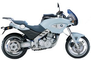
BMW F650 1994-2008 Workshop Repair & Service Manual

BMW F650 1994-2008

MBMWF6509408OPES.PDF
Price: $29.99 USD

Complete digital official shop manual contains service, maintenance, and troubleshooting information for the 1994-2008 BMW F650, F650CS, F650GS, F650ST, F650 Funduro, F650ST Strada. Diagnostic and repair procedures are covered in great detail to repair, maintain, rebuild, refurbish or restore your vehicle like a professional mechanic in local service/repair workshop. This cost-effective quality manual is 100% complete and intact as should be without any missing pages. It is the same factory shop manual used by dealers that guaranteed to be fully functional to save your precious time.

This manual for BMW F650 1994-2008 is divided into different sections. Each section covers a specific component or system and, in addition to the standard service procedures, includes disassembling, inspecting, and assembling instructions. A table of contents is placed at the beginning of each section. Pages are easily found by category, and each page is expandable for great detail. It is in the cross-platform PDF document format so that it works like a charm on all kinds of devices. You do not need to be skilled with a computer to use the manual.

’00-’08 F650GS (EN).pdf
’01-’06 F650CS (EN).pdf
’94-’00 F650, F650ST (EN).pdf
’00-’08 F650GS (DE).pdf
’94-’95 F650 (F650ST Strada, F650 Funduro) (FR).pdf
’94-’95 F650 (F650ST Strada, F650 Funduro) (ES).pdf

EXCERPT:
Contents
Group / Chapter
00 Tightening torques, Operating fluids
00 Pre-delivery check
00 Maintenance
11 Engine
12 Engine electrics
13 Fuel preparation and control
16 Fuel tank and lines
17 Radiator
18 Exhaust system
21 Clutch
23 Gearbox
27 Chain/belt drive
31 Front forks
32 Steering
33 Rear wheel drive
34 Brakes
36 Wheels and tires
46 Frame
51 Equipment
61 General electrical equipment
62 Instruments
63 Lights

17 40 000 Removing and installing fan
Remove right cover ( a 46.6).
Unclip the MoDiTeC plug from its holder.
Disconnect plug for fan.
Disengage the clips at top and bottom and remove the fan.
If necessary, remove fan from fan shroud.
Installation is the reverse of the removal procedure, pay particular attention to the following.
Slide the rubber grommet of the fan onto the pin of the expansion tank and then engage the tabs of the fan on the radiator.

33 Rear wheel drive
Technical Data …….. 3
Removing and installing suspension strut………5
Removing and installing rear swinging arm……6
Removing and installing needle roller races in rear swinging arm….8
Removing needle roller races ..8
Installing needle roller races ….8
Removing and installing needle bearings in rear swinging arm……..9
Removing needle roller bearing ………..9
Installing needle roller bearing ………..10
Removing and installing reaction link …..10
Removing and installing angled lever ….. 11
Removing and installing needle roller bearings and needle roller races in angled lever …….. 11
Removing needle roller bearings and needle roller races ……. 11
Installing needle roller bearings and needle roller races ……… 12
Removing and installing drive damper…..15
Measuring runout of belt pulley…13
Removing and installing eccentric with drive shaft
Separating eccentric from drive shaft 16
Removing and installing floating bearing of eccentric 16
Removing and installing fixed bearing of eccentric ….17
Pressing eccentric onto drive shaft …17

Contents
General view of crated motorcycle
Checking the shipping crate for damage
In case of damage in Germany
In case of damage in importer markets
Unpacking the motorcycle
Inspecting motorcycle for damage
Installing remaining items on motorcycle
Installing windscreen
Installing front mudguard, mirrors and handlebar weights
Filling and charging the battery
Removing right and centre covers
Filling and charging the battery
Checking that delivery is complete
Reading the fault code memory with the BMW MoDiTeC
Checking tyre pressures
Adding fuel to tank
Final inspection and function check
Final cleaning
Handing over the motorcycle

Inhalt
Übersicht Verpackung
Transportverschlag auf Schäden prüfen
Im Schadensfall in Deutschland
Im Schadensfall in Importeursmärkten
Motorrad auspacken
Motorrad auf Schäden prüfen
Motorrad komplettieren
Windschild anbauen
Vorderradkotflügel, Spiegel und Lenkergewichte anbauen
Batterie befüllen und laden
Cover rechts/mitte ausbauen
Batterie befüllen und laden
Vollständigen Lieferumfang prüfen
Fehlerspeicher mit BMW MoDiTeC auslesen
Reifenluftdruck prüfen
Kraftstoff einfüllen
Funktionsprüfung als Endkontrolle
Abschlußreinigung
Fahrzeugübergabe

23 00 622 Disassembling and reassembling compensating shaft
Clamp the compensating shaft in a vise fitted
with protective jaws.
Pull off gearwheels (1, 2).
Pull off needle roller bearing (3) and washer (4).
Pull off gearwheel (5).
Remove circlip (6) with special pliers,
BMW No. 23 4 500.
Pull off washer (7) and gearwheel (8).

Posted on

BMW Electrical Troubleshooting Manual & Owner’s Manual 1982-2006

BMW ETM & OM

MBMWETMOMOPES.PDF
Price: $29.99 USD

Complete digital Electrical Troubleshooting Manual & Owner’s Manual contains service, maintenance, and troubleshooting information for the 1982-2006 BMW cars. This manual is divided into different sections. A table of contents is placed at the beginning of each section. Pages are easily found by category, and each page is expandable for great detail. It is in the cross-platform PDF document format so that it works like a charm on all kinds of devices. You do not need to be skilled with a computer to use the manual.

MAKE: BMW
— — — — — — — — —
MODEL: Miscellaneous
— — — — — — — — —
YEAR: 1982 1983 1984 1985 1986 1987 1988 1989 1990 1991 1992 1993 1994 1995 1996 1997 1998 1999 2000 2001
— — — — — — — — —
LANGUAGE: English
— — — — — — — — —
TYPE: Electrical Troubleshooting Manual, Owner’s Manual
— — — — — — — — —
FORMAT: PDF (3.6GB)
— — — — — — — — —

├── ’00 Z3, Z3 Roadster, Z3 Coupe, M Roadster, M Coupe (E36_E37) ETM.pdf
├── ’01 Z3, Z3 Roadster, Z3 Coupe, M Roadster, M Coupe (E36_E37) ETM.pdf
├── ’82 5-Series (E28) 528e ETM.pdf
├── ’82 528e ETM.pdf
├── ’82 7-Series (E23) 733i ETM.pdf
├── ’82 735i ETM.pdf
├── ’83 528e – 533i ETM.pdf
├── ’83 633csi ETM.pdf
├── ’83 735i ETM.pdf
├── ’84 318i – 325e ETM.pdf
├── ’84 318i ETM.pdf
├── ’84 325e 318i ETM.pdf
├── ’84 528e – 533i ETM.pdf
├── ’84 633CSi ETM.pdf
├── ’84 735i ETM.pdf
├── ’85 318i – 325e ETM.pdf
├── ’85 524TD ETM.pdf
├── ’85 528e – 535i ETM.pdf
├── ’85 635CSi ETM.pdf
├── ’85 735i ETM.pdf
├── ’86 325 ETM.pdf
├── ’86 524TD ETM.pdf
├── ’86 528e – 535i ETM.pdf
├── ’86 635CSi ETM.pdf
├── ’86 735i ETM.pdf
├── ’87 325, 325e, 325es, 325i, 325is, 325i Convertible ETM.pdf
├── ’87 735i (E32) ETM.pdf
├── ’87 L6 – M6 ETM.pdf
├── ’87 M3 ETM.pdf
├── ’87-’88 528e ETM.pdf
├── ’87-’88 535i, M5 ETM.pdf
├── ’88 5- (E34), 7- Series (E32) ETM (’88&up, 1,783 pages).pdf
├── ’88 325 – 325i – 325is ETM.pdf
├── ’88 325 325i 325is ETM.pdf
├── ’88 325i Convertible ETM.pdf
├── ’88 325iX ETM.pdf
├── ’88 525i – 535i (E34) ETM.pdf
├── ’88 635CSi – M6 ETM.pdf
├── ’88 735i – 735iL – 750iL (E32) ETM.pdf
├── ’88 M3 ETM.pdf
├── ’88-’89 5-Series (E34) 525i, 535i ETM.pdf
├── ’89 325i – 325is ETM.pdf
├── ’89 325i Convertible ETM.pdf
├── ’89 325ix ETM.pdf
├── ’89 525i – 535i (E34) ETM.pdf
├── ’89 635CSi – ETM.pdf
├── ’89 735i – 735iL – 750iL (E32) ETM.pdf
├── ’89 M3 ETM.pdf
├── ’90 325i Convertible ETM.pdf
├── ’90 325iX ETM.pdf
├── ’90 525i – 535i – M5 (E34) ETM.pdf
├── ’90 735i – 735iL – 750iL (E32) ETM.pdf
├── ’90 M3 ETM.pdf
├── ’91 318i – 318is – 318ic ETM.pdf
├── ’91 325i ETM.pdf
├── ’91 525i – 535i – M5 (E34) ETM.pdf
├── ’91 735i – 735iL – 750iL (E32) ETM.pdf
├── ’91 850i (E31) ETM.pdf
├── ’92 318ic ETM.pdf
├── ’92 318is – 325i (E36) ETM.pdf
├── ’92 325i Convertible ETM.pdf
├── ’92 525i – 525it – 535i – M5 (E34) ETM.pdf
├── ’92 735i – 735iL – 750iL (E32) ETM.pdf
├── ’92 850i (E31) ETM.pdf
├── ’93 318i – 318is – 325i – 325is (E36) ETM.pdf
├── ’93 525i – 525it – 535i – M5 (E34) ETM.pdf
├── ’93 740i – 740iL – 750iL (E32) ETM.pdf
├── ’93 850i (E31) ETM.pdf
├── ’93-’94 318i(s)(c), 320i, 325(i)(s)(c), M3 (E36) ETM.pdf
├── ’94 318i, 318s, 318c, 320i, 325i, 325s, 325c, M3 (E36) ETM.pdf
├── ’94 5-Series (E34) 518i, 520i, 525td, 525tds, incl. touring ETM.pdf
├── ’94 525i – 525it – 530i – 530it – 540i (E34) ETM.pdf
├── ’94 840Ci – 850Ci – 850CSi (E31) ETM.pdf
├── ’95 318i, 318s, 318c, 320i, 325i, 325s, 325c, M3 (E36) ETM.pdf
├── ’95 318ti (E35_E36) ETM.pdf
├── ’95 525i – 525it – 530i – 530it – 540i (E34) ETM.pdf
├── ’95-’96 840Ci – 850Ci – 850CSi (E31) ETM.pdf
├── ’96 318is, 318ic, 320i, 325i, 325ic , 328i, 328ic, M3 (E36) ETM.pdf
├── ’96 318ti (E35_E36) ETM.pdf
├── ’96 Z3 (E36_E37) ETM.pdf
├── ’96 Z3 Roadster (E36_E37) ETM.pdf
├── ’97 318is, 318ic, 328i, 328ic, M3 (E36) ETM.pdf
├── ’97 318ti (E35_E36) ETM.pdf
├── ’98 318is, 318ic, 323i, 323ic, 328i, 328ic, M3, M3c (E36) ETM.pdf
├── ’98 318ti (E35_E36) ETM.pdf
├── ’98 Z3, Z3 Roadster, M Roadster (E36_E37) ETM.pdf
├── ’99 318is(C), 323is(C), 328is(C), M3 (E36) ETM.pdf
├── ’99 318ti (E35_E36) ETM.pdf
├── ’99 Z3, Z3 Roadster, Z3 Coupe, M Roadster, M Coupe (E36_E37) ETM.pdf
└── 8-Series (E31) ETM Diagnostic Procedures.pdf
├── 2004 325Ci Convertible Owner’s Manual.pdf
├── 2004 325Ci Coupe Owner’s Manual.pdf
├── 2004 325i Owner’s Manual.pdf
├── 2004 325i Wagon Owner’s Manual.pdf
├── 2004 325iT Wagon Owner’s Manual.pdf
├── 2004 325xi Owner’s Manual.pdf
├── 2004 325xi Wagon Owner’s Manual.pdf
├── 2004 330Ci Convertible Owner’s Manual.pdf
├── 2004 330Ci Coupe Owner’s Manual.pdf
├── 2004 330i Owner’s Manual.pdf
├── 2004 330xi Owner’s Manual.pdf
├── 2004 525i Owner’s Manual.pdf
├── 2004 530i Owner’s Manual.pdf
├── 2004 545i 6 Speed Sedan Owner’s Manual.pdf
├── 2004 545i Owner’s Manual.pdf
├── 2004 645Ci Convertible Owner’s Manual.pdf
├── 2004 645Ci Coupe Owner’s Manual.pdf
├── 2004 745Li Owner’s Manual.pdf
├── 2004 745i Owner’s Manual.pdf
├── 2004 760Li Owner’s Manual.pdf
├── 2004 760i Sedan Owner’s Manual.pdf
├── 2004 M3 Convertible Owner’s Manual.pdf
├── 2004 M3 Coupe Owner’s Manual.pdf
├── 2004 X3 2-5i Owner’s Manual.pdf
├── 2004 X3 3-0i Owner’s Manual.pdf
├── 2004 X5 3-0i Owner’s Manual.pdf
├── 2004 X5 4-4i Owner’s Manual.pdf
├── 2004 X5 4-8is SAV Owner’s Manual.pdf
├── 2004 Z4 2-5i Owner’s Manual.pdf
├── 2004 Z4 3-0i Owner’s Manual.pdf
├── 2005 325Ci Convertible Owner’s Manual.pdf
├── 2005 325Ci Owner’s Manual.pdf
├── 2005 325i Sports Wagon Owner’s Manual.pdf
├── 2005 325i with iDrive Owner’s Manual.pdf
├── 2005 325i without iDrive Owner’s Manual.pdf
├── 2005 325xi Sports Wagon Owner’s Manual.pdf
├── 2005 325xi with iDrive Owner’s Manual.pdf
├── 2005 325xi without iDrive Owner’s Manual.pdf
├── 2005 330Ci Convertible Owner’s Manual.pdf
├── 2005 330Ci Owner’s Manual.pdf
├── 2005 330i with iDrive Owner’s Manual.pdf
├── 2005 330i without iDrive Owner’s Manual.pdf
├── 2005 330xi with iDrive Owner’s Manual.pdf
├── 2005 330xi without iDrive Owner’s Manual.pdf
├── 2005 525i Owner’s Manual.pdf
├── 2005 530i Owner’s Manual.pdf
├── 2005 545i Owner’s Manual.pdf
├── 2005 645Ci Owner’s Manual.pdf
├── 2005 745Li Owner’s Manual.pdf
├── 2005 745i Owner’s Manual.pdf
├── 2005 760Li Owner’s Manual.pdf
├── 2005 760i Owner’s Manual.pdf
├── 2005 M3 Convertible Owner’s Manual.pdf
├── 2005 M3 Coupe Owner’s Manual.pdf
├── 2005 MINI All Models.pdf
├── 2005 X3 2.5i Owner’s Manual.pdf
├── 2005 X3 3.0i Owner’s Manual.pdf
├── 2005 X5 3.0i Owner’s Manual.pdf
├── 2005 X5 4.4i Owner’s Manual.pdf
├── 2005 X5 4.8is Owner’s Manual.pdf
├── 2005 Z4 2.5i Owner’s Manual.pdf
├── 2005 Z4 3.0i Owner’s Manual.pdf
├── 2006 325Ci Coupe with iDrive Owner’s Manual.pdf
├── 2006 325Ci Coupe without iDrive Owner’s Manual.pdf
├── 2006 325i with iDrive Owner’s Manual.pdf
├── 2006 325i without iDrive Owner’s Manual.pdf
├── 2006 325xi Wagon with iDrive Owner’s Manual.pdf
├── 2006 325xi Wagon without iDrive Owner’s Manual.pdf
├── 2006 325xi with iDrive Owner’s Manual.pdf
├── 2006 325xi without iDrive Owner’s Manual.pdf
├── 2006 330Ci Coupe with iDrive Owner’s Manual.pdf
├── 2006 330Ci Coupe without iDrive Owner’s Manual.pdf
├── 2006 330i with iDrive Owner’s Manual.pdf
├── 2006 330i without iDrive Owner’s Manual.pdf
├── 2006 330xi with iDrive Owner’s Manual.pdf
├── 2006 330xi without iDrive Owner’s Manual.pdf
├── 2006 525i Owner’s Manual.pdf
├── 2006 525xi Owner’s Manul.pdf
├── 2006 530i Owner’s Manual.pdf
├── 2006 530xi Owner’s Manual.pdf
├── 2006 530xi Sports Wagon Owner’s Manual.pdf
├── 2006 550i Owner’s Manual.pdf
├── 2006 650i Convertible Owner’s Manual.pdf
├── 2006 650i Coupe Owner’s Manual.pdf
├── 2006 750Li Owner’s Manual.pdf
├── 2006 750i Owner’s Manual.pdf
├── 2006 760Li Owner’s Manual.pdf
├── 2006 760i Owner’s Manual.pdf
├── 2006 M3 Convertible Owner’s Manual.pdf
├── 2006 M3 Coupe Owner’s Manual.pdf
├── 2006 M5 Owner’s Manual.pdf
├── 2006 M6 Owner’s Manual.pdf
├── 2006 X3 3.0i SAV Owner’s Manual.pdf
├── 2006 X5 3.0i SAV Owner’s Manual.pdf
├── 2006 X5 4.4i SAV Owner’s Manual.pdf
├── 2006 X5 4.8is SAV Owner’s Manual.pdf
├── 2006 Z4 3.0i Roadster Owner’s Manual.pdf
├── 2006 Z4 3.0si Roadster Owner’s Manual.pdf
├── 2006 Z4 Coupe Owner’s Manual.pdf
├── 2006 Z4 M Coupe Owner’s Manual.pdf
└── 2006 Z4 M Roadster Owner’s Manual.pdf

— — — — — — — — —
’82-’94 5-6-7-Series (E23-24-28-32-34) ETM
564MB PDF,
BMW 5-Series:
E28:
528e 1982
528e, 533i 1983
528e, 533i 1984
528e, 533i 1985
528e, 533i 1986
528e 1987/1988
535i, M5 1987/1988
524TD 1985
524TD 1986
E34:
525i, 535i 1989
525i, 535i 1989 (2/89 and later)
525i, 535i, M5 1990
525i, 535i, M5 1991
525i, 525it, 535i, M5 1992
525i, 525it, 535i, M5 1993
525i, 525it, 530i, 530it, 540i 1994
525i, 525it, 530i, 530it, 540i 1995
BMW 6-Series:
E24:
633CSi 1983
633CSi 1984
635CSi 1985
635CSi 1986
L6 / M6 1987
635CSi / M6 1988
635CSi 1989
BMW 7-Series:
E23:
733i 1982
733i 1983
733i 1984
735i 1985
735i / L7 1986/1987
E32:
735i 1988
735i, 735iL, 750iL 1988
735i, 735iL, 750iL 1989
735i, 735iL, 750iL 1990
735i, 735iL, 750iL 1991
735i, 735iL, 750iL 1992
740i, 740iL, 750iL 1993/1994
— — — — — — — — —
’84-’98 3-8-Series (E30, E31, E36) ETM
535MB PDF
BMW 3-Series:
E30:
318i 1984
325e, 318i 1984
325e, 318i 1985
325e 1986
325, 325e, 325es, 325i, 325is, 325i Conv. 1987
325, 325i, 325is 1988
325i, 325is 1989
325iX 1988
325iX 1989
325iX 1990
325i Convertible 1988
325i Convertible 1989
325i Convertible 1990
325i Convertible 1992
M3 1987
M3 1988
M3 1989
M3 1990
325i, 325iX, 325ic, M3 1991
318i, 318is, 318ic 1991
318ic 1992
E36:
318is, 325i 1992
318i, 318is, 325i, 325is 1993
318i, 318is, 318ic, 320i, 325i, 325is, 325ic, M3 1994
318i, 318is, 318ic, 320i, 325i, 325is, 325ic, M3 1995
318i, 325i, 325ic, 328i, 328ic, M3 1996
318is/c, 328i/c, M3 1997
318is/c, 323i/c, 328i/c, M3/c 1998
E36/5 Compact:
318ti 1995
318ti 1996
318ti 1997
318ti 1998
E36/7 Z 3:
Z 3 Roadster 1996
Z 3 Roadster 1997
Z 3 Roadster 1998
BMW 8-Series:
E31:
850i 1991
850i 1992
850i 1993
840Ci, 850Ci, 850CSi 1994
840Ci, 850Ci, 850CSi 1995/1996
— — — — — — — — —
’98-’01 3-Series (E36) ETM
363MB PDF
1998 E36:
Series 3 – E36 (316i, 318i, 318is, 320i, 323i, 328i, M3, 318tds, 325td, 325tds incl. Convertible and Touring)
1999 E36:
Series 3 – E36 (Coupé, Convertible and Touring)
1998 E36/5 Compact:
Series 3 – E36/5 compact (316i, 316g, 318ti, 318tds, 323ti)
1999 E36/5 Compact:
Series 3 – E36/5 compact (316i, 316g, 318ti, 318tds, 323ti)
2000 E36/5 Compact:
Series 3 – E36/5 compact (316i, 316g, 318tds, 323ti)
2000 E36/5 Compact (RHD):
Series 3 – E36/5 compact (316i, 316g, 318ti, 318tds, 323ti)
1998 E36/7 Z3:
Series 3 – E36/7 (Z3 Roadster)
1999 E36/7 Z3:
Series 3 – E36/7 (Z3 Roadster and Coupé)
2000 E36/7 Z3:
Series 3 – E36/7 (Z3 Roadster and Coupé)
2001 E36/7 Z3:
Series 3 – E36/7 (Z3 Roadster and Coupé)
2000 E36/7 Z3 (RHD):
Series 3 – E36/7 (Z3 Roadster and Coupé)
2001 E36/7 Z3 (RHD):
Series 3 – E36/7 (Z3 Roadster and Coupé)
— — — — — — — — —

Posted on

BMW Alpina B7 2003-2008 Workshop Repair & Service Manual

BMW Alpina B7 2003-2008


INSTANT DOWNLOAD


Complete digital official shop manual contains service, maintenance, and troubleshooting information for the 2003-2008 BMW Alpina B7 (E65/E66 Series). Diagnostic and repair procedures are covered in great detail to repair, maintain, rebuild, refurbish or restore your vehicle like a professional mechanic in local service/repair workshop. This cost-effective quality manual is 100% complete and intact as should be without any missing pages. It is the same factory shop manual used by dealers that guaranteed to be fully functional to save your precious time.

This manual for 2003-2008 BMW Alpina B7 (E65/E66 Series) is divided into different sections. Each section covers a specific component or system and, in addition to the standard service procedures, includes disassembling, inspecting, and assembling instructions. A table of contents is placed at the beginning of each section. Pages are easily found by category, and each page is expandable for great detail. It is in the cross-platform PDF document format so that it works like a charm on all kinds of devices. You do not need to be skilled with a computer to use the manual.

FILE LIST:ACCESSORIES & BODY, CAB Audio – SI Techniques – E60, E61, E63, E64, E65, E66.pdf
ACCESSORIES & EQUIPMENT Body Equipment – Operating Fluids.pdf
ACCESSORIES & EQUIPMENT Car Care Products – Operating Fluids.pdf
ACCESSORIES & EQUIPMENT Communication System – Tightening Torques.pdf
ACCESSORIES & EQUIPMENT Lights – Special Tools.pdf
ACCESSORIES & EQUIPMENT Night Vision, Cruise Control – Overview.pdf
ACCESSORIES & EQUIPMENT Seats – Operating Fluids.pdf
ACCESSORIES & EQUIPMENT Seats – Special Tools.pdf
ACCESSORIES & EQUIPMENT Vehicle Lighting – Product Information.pdf
ACCESSORIES AND BODY, CAB Audio, Navigation and Anti-Theft – Repair Instructions.pdf
ACCESSORIES AND BODY, CAB Audio, Navigation and Anti-Theft – SI Techniques.pdf
ACCESSORIES AND BODY, CAB Audio, Navigation and Anti-Theft – Special Tools.pdf
ACCESSORIES AND BODY, CAB Audio, Navigation and Anti-Theft – Tightening Torques.pdf
ACCESSORIES AND BODY, CAB Body Equipment – Repair Instructions.pdf
ACCESSORIES AND BODY, CAB Body Equipment – Special Tools.pdf
ACCESSORIES AND BODY, CAB Body Equipment – Tightening Torques.pdf
ACCESSORIES AND BODY, CAB Communication Systems – Repair Instructions.pdf
ACCESSORIES AND BODY, CAB Cruise Control – Special Tools.pdf
ACCESSORIES AND BODY, CAB Cruise Control Systems – Repair Instructions.pdf
ACCESSORIES AND BODY, CAB Distance Systems, Cruise Control – SI Techniques.pdf
ACCESSORIES AND BODY, CAB Distance Systems, Cruise Control – Tightening Torque.pdf
ACCESSORIES AND BODY, CAB Electrical Drives – Repair Instructions.pdf
ACCESSORIES AND BODY, CAB Electrical Drives – Tightening Torques.pdf
ACCESSORIES AND BODY, CAB General Electrical System – Repair Instructions.pdf
ACCESSORIES AND BODY, CAB General Electrical System – SI Techniques.pdf
ACCESSORIES AND BODY, CAB General Electrical System – Special Tools.pdf
ACCESSORIES AND BODY, CAB General Electrical System – Technical Data.pdf
ACCESSORIES AND BODY, CAB General Electrical System – Tightening Torques.pdf
ACCESSORIES AND BODY, CAB Instruments – Repair Instructions.pdf
ACCESSORIES AND BODY, CAB Instruments – SI Techniques.pdf
ACCESSORIES AND BODY, CAB Instruments – Special Tools.pdf
ACCESSORIES AND BODY, CAB Lights – Repair Instructions.pdf
ACCESSORIES AND BODY, CAB Lights – SI Techniques.pdf
ACCESSORIES AND BODY, CAB Lights – Technical Data.pdf
ACCESSORIES AND BODY, CAB Parts & Accessories – Repair Instructions.pdf
ACCESSORIES AND BODY, CAB Seats – Repair Instructions.pdf
ACCESSORIES AND BODY, CAB Seats – Tightening Torques.pdf
ACCESSORIES AND BODY, CAB Trailer Hitch – Tightening Torques.pdf
ACCESSORIES AND BODY, CAB Trailers – Repair Instructions.pdf
ACCESSORIES AND BODY, CAB Trailers – Tightening Torques.pdf
AUTOMATIC TRANSMISSION Diagnostic Trouble Codes – 6-Speed ZF Transmission.pdf
BRAKES Brakes – Operating Fluids.pdf
BRAKES Brakes – Repair Instructions.pdf
BRAKES Brakes – Special Tools.pdf
BRAKES Brakes – Technical Data.pdf
BRAKES Brakes – Tightening Torques.pdf
BRAKES Pedals – Operating Fluids.pdf
BRAKES Pedals – Repair Instructions.pdf
BRAKES Pedals – Tightening Torques.pdf
CABIN AIR FILTER.pdf
DRIVELINEAXLE Rear Axle – Operating Fluids.pdf
DRIVELINEAXLES Front Axle – Operating Fluids.pdf
DRIVELINEAXLES Propeller Shaft – Operating Fluids.pdf
DRIVELINEAXLES Propeller Shaft – Repair Instructions – Alpina.pdf
DRIVELINEAXLES Propeller Shaft – Special Tools.pdf
DRIVELINEAXLES Propeller shaft – Technical Data.pdf
DRIVELINEAXLES Propeller Shaft – Tightening Torques.pdf
DRIVELINEAXLES Rear Axle – SI Techniques.pdf
ELECTRICAL BMW – 7 Series (E65E66).pdf
ELECTRICAL Electrical System – Operating Fluids.pdf
ELECTRICAL Engine Electrical System – Special Tools.pdf
ELECTRICAL Fuse Assignment Symbol Definitions.pdf
ENGINE Cooling System – Operating Fluids.pdf
ENGINE Cooling system – Repair Instructions.pdf
ENGINE Cooling system – Special Tools.pdf
ENGINE Cooling System – Technical Data.pdf
ENGINE Cooling system – Tightening Torques.pdf
ENGINE Engine – Operating Fluids.pdf
ENGINE Engine – Repair Instructions.pdf
ENGINE Engine – Special Tools.pdf
ENGINE Engine – Technical Data .pdf
ENGINE Engine – Technical Data.pdf
ENGINE Engine – Tightening Torques.pdf
ENGINE Engine and Gearbox Suspension – Repair Instructions.pdf
ENGINE Engine And Gearbox Suspension – Tightening Torques.pdf
ENGINE Engine Electrical System – Repair Instructions.pdf
ENGINE Engine Electrical System – Tightening Torques.pdf
ENGINE Exhaust System – Operating Fluids.pdf
ENGINE Exhaust System – Repair Instructions.pdf
ENGINE Exhaust system – Tightening Torques.pdf
ENGINE Fuel Supply System – Repair Instructions.pdf
ENGINE Fuel Supply System – Special Tools.pdf
ENGINE Fuel Supply System – Technical Data.pdf
ENGINE Fuel Supply System – Tightening Torques.pdf
ENGINE Fuel System – Operating Fluids.pdf
ENGINE PERFORMANCE Diagnostic Trouble Codes – ME9.2.2 Engine Operating System – DTC P0010 to P1199.pdf
ENGINE PERFORMANCE Diagnostic Trouble Codes – ME9.2.2 Engine Operating System – DTC P1230 – U1135.pdf
ENGINE PERFORMANCE Firing Order & Cylinder Identification.pdf
ENGINE PERFORMANCE Fuel System – Repair Instructions.pdf
ENGINE PERFORMANCE Fuel System – Technical Data.pdf
ENGINE PERFORMANCE Fuel system – Tightening Torques.pdf
ENGINEPERFORMANCE Fuel System – Special Tools.pdf
GENERAL INFORMATION Alpina B7 – Overview.pdf
GENERAL INFORMATION Basic Engine Measuring Techniques – Overview.pdf
GENERAL INFORMATION BMW Model Identification.pdf
GENERAL INFORMATION BMW Night Vision – Overview.pdf
GENERAL INFORMATION BMW Universal Bluetooth – Overview.pdf
GENERAL INFORMATION Breakout Boxes & Connectors – Overview.pdf
GENERAL INFORMATION Charging Systems – Overview.pdf
GENERAL INFORMATION Chassis Dynamics – Overview.pdf
GENERAL INFORMATION CIP Programming – Overview.pdf
GENERAL INFORMATION Diagnostic Connector (DLC) Locations.pdf
GENERAL INFORMATION DVOM – Overview.pdf
GENERAL INFORMATION Electronic Signals – Overview.pdf
GENERAL INFORMATION Electronic Transmission Control – Overview.pdf
GENERAL INFORMATION Emissions – Overview.pdf
GENERAL INFORMATION Engine Diagnosis – Overview.pdf
GENERAL INFORMATION Euro English-to-U.S. Translations.pdf
GENERAL INFORMATION Maintenance & General Information – SI Techniques.pdf
GENERAL INFORMATION Maintenance & General Information – Special Tools.pdf
GENERAL INFORMATION Maintenance & General Information – Tightening Torques.pdf
GENERAL INFORMATION New Engine Technology – Overview.pdf
GENERAL INFORMATION Passive Safety System.pdf
GENERAL INFORMATION Starting Systems – Overview.pdf
GENERAL INFORMATION Telephone Diagnostics – Overview – All Models.pdf
GENERAL INFORMATION The Battery – Overview.pdf
GENERAL INFORMATION Transmission Fundamentals – Overview.pdf
GENERAL INFORMATION Undercar Technology – Overview.pdf
GENERAL INFORMATION Understanding Diagnostics – Overview.pdf
HVAC Heating & Air Conditioning – Repair Instructions.pdf
HVAC Heating & Air Conditioning – Special Tools.pdf
HVAC Heating & Air Conditioning – Technical Data.pdf
HVAC Heating & Air Conditioning – Tightening Torques.pdf
HVAC Heating and Air Conditioning – Operating Fluids.pdf
MAINTENANCE Maintenance & General Information – Repair Instructions.pdf
MAINTENANCE Maintenance and General Information – Operating Fluids.pdf
Printing from undefined.pdf
REMINDER INDICATOR RESET PROCEDURES BMW – 1982-14.pdf
RESTRAINTS Parts & Accessories – Tightening Torques.pdf
STEERING Steering – Operating Fluids.pdf
STEERING Steering And Wheel Alignment – SI Techniques.pdf
SUSPENSION Front Axle – Repair Instructions.pdf
SUSPENSION Front Axle – Special Tools.pdf
SUSPENSION Front Axle – Technical Data.pdf
SUSPENSION Front Axle – Tightening Torques.pdf
SUSPENSION Integrated Suspension Systems – Operating Fluids.pdf
SUSPENSION Integrated Suspension Systems – Repair Instructions.pdf
SUSPENSION Integrated Suspension Systems – Tightening Torques.pdf
SUSPENSION Rear Axle – Repair Instructions.pdf
SUSPENSION Rear Axle – Special Tools.pdf
SUSPENSION Rear Axle – Technical Data.pdf
SUSPENSION Rear Axle – Tightening Torques.pdf
SUSPENSION Steering And Wheel Alignment – Repair Instructions.pdf
SUSPENSION Steering And Wheel Alignment – Special Tools.pdf
SUSPENSION Steering And Wheel Alignment – Technical Data.pdf
SUSPENSION Steering And Wheel Alignment – Tightening Torques.pdf
SUSPENSION Suspension – Special Tools.pdf
SUSPENSION Wheel And Tires – Repair Instructions.pdf
SUSPENSION Wheel And Tires – SI Techniques.pdf
SUSPENSION Wheel And Tires – Special Tools.pdf
SUSPENSION Wheel And Tires – Technical Data.pdf
SUSPENSION Wheel And Tires – Tightening Torques.pdf
SUSPENSION Wheels And Tires – Operating Fluids.pdf
TIRE PRESSURE MONITOR SYSTEMS BMW – 7-Series (E65-E66).pdf
TRANSMISSION Automatic Transmission – Operating Fluids.pdf
TRANSMISSION Automatic Transmission – Repair Instructions.pdf
TRANSMISSION Automatic Transmission – SI Techniques.pdf
TRANSMISSION Automatic Transmission – Special Tools.pdf
TRANSMISSION Automatic Transmission – Technical Data.pdf
TRANSMISSION Gear Shift Mechanism – Operating Fluids.pdf
TRANSMISSION Manual Transmission – Operating Fluids.pdf
TRANSMISSION Transfer Box – Repair Instructions.pdf
TRANSMISSION Transfer Case – Operating Fluids.pdf

EXCERPT:
2007-08 ENGINE Cooling system – Repair Instructions – Alpina
22 OIL COOLER LINES
17 21 500 FLUSHING OIL COOLER WITH LINES (AUTOMATIC TRANSMISSION)
Special tools required:
 17 2 018
 17 2 019
Procedure:
Automatic transmission removed.
Connect appropriate adapters (see description below) to oil lines exiting from automatic transmission.
Connect the connecting line 17 2 019 from the oil collection unit with the quick-release coupling.
Connect drain line 17 2 018 using quick-release coupling.
Feed open end of drain line into a suitable collection container.
Using oil collection unit, flush approx. 1 liter of transmission fluid (refer to AUTOMATIC TRANSMISSION – OPERATING FLUIDS ) through oil lines and oil cooler.
Reposition quick-release couplings.
Flush oil lines/oil cooler in opposite direction with approx. 1 liter of transmission fluid (refer to AUTOMATIC TRANSMISSION – OPERATING FLUIDS ).
Disconnect quick-release couplings, remove adapters.
Arrangement of flushing device for transmissions A5S 310Z, A5S 560Z, A5S 360R/390R, A4S 200R, A5S 325Z, GA6HP26Z
NOTE: Carry out the work steps listed when:
Fitting a new or replacement transmission
Flushing can only be carried out with the automatic transmission removed.
NOTE: Dispose of flushing oil properly; do not under any circumstances reuse it.
Fig. 87: Arrangement Of Flushing Device For Transmissions A5S 310Z, A5S 560Z, A5S 360R/390R
1. Transmission-oil cooler with lines
2. Oil collection unit
3. Oil drip tray
17 2 011 Adapter for connecting transmission-side oil cooler lines (1)
17 2 015 Connection for oil collection unit (2), manufacturer: Deutsche Tecalemit or
17 2 016 Connection for oil collection unit (2), manufacturer: Horn
17 2 017 Quick-release coupling (2 pieces)
17 2 018 Hose to oil drip tray (3)
17 2 019 Hose to oil collection unit (2)


INSTANT DOWNLOAD


Posted on

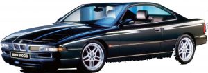
BMW 840Ci/850i/850Ci/850CSi 1991-1997 Workshop Repair & Service Manual

BMW 840-850 1991-1997

MBMW840NPES.PDF
Price: $29.99 USD

Complete digital official shop manual contains service, maintenance, and troubleshooting information for the 1991-1997 BMW 840Ci, 850i, 850Ci, 850CSi. Diagnostic and repair procedures are covered in great detail to repair, maintain, rebuild, refurbish or restore your vehicle like a professional mechanic in local service/repair workshop. This cost-effective quality manual is 100% complete and intact as should be without any missing pages. It is the same factory shop manual used by dealers that guaranteed to be fully functional to save your precious time.

This manual for 1991-1997 BMW 840Ci/850i/850Ci/850CSi is divided into different sections. Each section covers a specific component or system and, in addition to the standard service procedures, includes disassembling, inspecting, and assembling instructions. A table of contents is placed at the beginning of each section. Pages are easily found by category, and each page is expandable for great detail. It is in the cross-platform PDF document format so that it works like a charm on all kinds of devices. You do not need to be skilled with a computer to use the manual.

BMW 840Ci 1994-1997
BMW 850i 1991-1992
BMW 850Ci 1993-1997
BMW 850CSi 1994-1995

EXCERPT:
1995-01 ENGINES BMW – 5.4L V12
FLYWHEEL & RING GEAR
Removal & Installation
1. Block flywheel using Holder (11 2 070). See Fig. 30 . Remove flywheel bolts. Remove drive plate.
Remove flywheel. See Fig. 31 .
2. To install, reverse removal procedure. Clean flywheel bolt threads in crankshaft. Flywheel is secured with a dowel sleeve. Install flywheel and mount drive plate for torque converter. Holes in drive plate and flywheel must be aligned. See Fig. 32 . Install new flywheel bolts. See TORQUE SPECIFICATIONS .
Fig. 30: Blocking Flywheel
CAUTION: Whenever flywheel is removed, impulse sensor must be reset.
Fig. 31: Removing Drive Plate & Flywheel
Fig. 32: Installing Drive Plate & Flywheel
FAN COUPLING
Removal & Installation
1. Lock belt pulley in position using Holder (11 5 050). See Fig. 33 . Remove cap nut with Open-End Spanner (11 5 040). Remove fan wheel with fan coupling from water pump. Remove bolts and detach fan from fan coupling. See Fig. 34 .
2. To install, reverse removal procedure. For tightening torque, see TORQUE SPECIFICATIONS.
NOTE: Fan coupling utilizes left hand threads
NOTE: Tightening torque of 30 ft. lbs (40 N.m) when using Open-End Spanner (11 5 040) is equivalent to 22 ft. lbs. (30 N.m) on torque wrench scale.
Fig. 33: Locking Belt Pulley In Position
Fig. 34: Removing Fan Coupling From Fan
COOLANT THERMOSTAT
Removal & Installation
1. Drain coolant. Remove complete fan assembly. See FAN COUPLING under REMOVAL & INSTALLATION . Remove non-return valve for cylinders No. 1-6. See NON-RETURN VALVE under REMOVAL & INSTALLATION. Remove bolts and thermostat housing. Remove thermostat.
2. To install, reverse removal procedure. Clean sealing faces and replace gasket. Note support bracket for delivery pipe and stabilizer for drive belt. See Fig. 35 . Install thermostat with vent bore pointing upwards, then fit new gasket. See Fig. 36 . Bleed cooling system and check for water leaks.
Fig. 35: Identifying Bracket For Delivery Pipe & Stabilizer
Fig. 36: Installing New Gasket On Thermostat
COOLANT MANIFOLD
Removal & Installation
1. Remove both cylinder head covers. Remove splash guard. Remove left heat baffle plate from front axle support. Unfasten coolant drain plug from left side of engine. Drain coolant. Mark plug connection for impulse sensor on crankshaft (flywheel), press down interlock on connector and disconnect connector.
See Fig. 37 and Fig. 38 .
2. Unclip wiring harness on transmission and remove from brackets behind cylinder head. Unfasten hose clip. Remove coolant hose from back of coolant pipe. See Fig. 39 . Remove hose clip and remove coolant hose from back of cylinder head. See Fig. 40 . Remove hose clips on coolant hoses on face wall of heating unit. See Fig. 41 . Remove bolt.
3. Loosen bolts on cylinder head for cylinders No. 7-12. See Fig. 42 . Loosen bolts on cylinder head for cylinders No. 1-6. See Fig. 43 . Remove coolant manifold. Remove coolant pipes. See Fig. 44 . To install, reverse removal procedure. Clean sealing faces behind cylinder heads and coolant manifold. Replace gaskets. Replace sealing ring. See TORQUE SPECIFICATIONS . Top off coolant. Bleed cooling system and check for water leaks. Replace “O” rings. See Fig. 45 . Coat “O” rings with anti-friction agent and replace cooling pipe.
Fig. 37: Identifying Impulse Sensor For DME 1