Posted on

Ford New Holland 60 Series Tractors (8160, 8260, 8360, 8560) Factory Service & Shop Manual

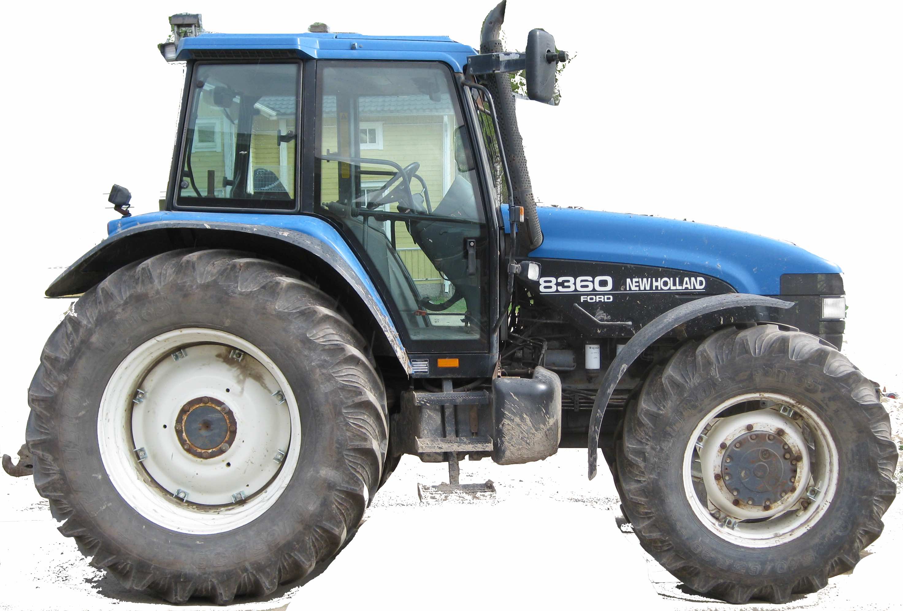
New Holland_Ford 8160, 8260, 8360, 8560


INSTANT DOWNLOAD


Complete workshop & service manual with electrical wiring diagrams for Ford New Holland 60 Series Tractors (8160, 8260, 8360, 8560). It’s the same service manual used by dealers that guaranteed to be fully functional and intact without any missing page.

This Ford New Holland 60 Series Tractors (8160, 8260, 8360, 8560) service & repair manual (including maintenance, overhaul, disassembling & assembling, adjustment, tune-up, operation, inspecting, diagnostic & troubleshooting…) is divided into different sections. Each section covers a specific component or system with detailed illustrations. A table of contents is placed at the beginning of each section. Pages are easily found by category, and each page is expandable for great detail. The printer-ready PDF documents work like a charm on all kinds of devices.

“40816040.pdf”
Ford New Holland 60 Series Tractors (8160, 8260, 8360, 8560) Service Manual
1,414 pages PDF
Part number 40816040 English
Ford New Holland 60 Series Tractors (8160, 8260, 8360, 8560) Repair Manual

— — —

“86588680.pdf”
Ford New Holland 8160 8260 8360 8560 Section 2 – Electrical System Supplement
280 pages

EXCERPT:
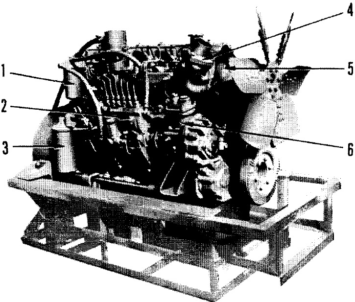
SECTION 1 – ENGINES (Engine)
DIESEL ENGINE-DESCRIPTION AND OPERATION
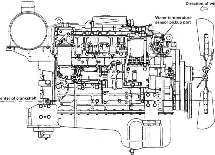
The engines are 6 cylinder and available in naturally aspirated and turbocharged forms.
All engines feature cross flow cylinder heads, with the inlet and exhaust manifolds on opposite sides of the cylinder head. The fuel and air combustion process, takes place in the specially designed bowl in the crown of the pistons.
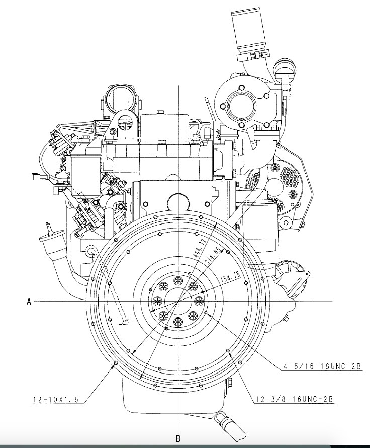
CYLINDER HEAD ASSEMBLY
The cylinder head incorporates valves and springs, with the valve rocker arm shaft assembly bolted to the cylinder block through the cylinder head. Cylinder head retaining bolts are evenly spaced with a six point pattern around each cylinder, this ensures an even clamping load across the cylinder head area.
The intake and exhaust manifolds are bolted to the head, the intake manifold is mounted on the right hand side of the engine, with the diesel injectors mounted outside the rocker cover. The exhaust manifold is mounted on the left hand side of the engine. Water outlet connections and thermostat being attached to the front of the cylinder block directly behind the radiator.


INSTANT DOWNLOAD


Posted on

Komatsu 108 Series Diesel Engines Factory Service & Shop Manual

Pages from SEBM006904 – 108-2 Series Diesel Engines Shop Manual

MKMTSENG108OPES.PDF
Price: $29.99 USD

Complete workshop & service manual with electrical wiring diagrams for Komatsu 108 Series Diesel Engines (S6D108-1, SA6D108-1, S6D108-2, SA6D108-2, SAA6D108-2). It’s the same service manual used by dealers that guaranteed to be fully functional and intact without any missing page.

This Komatsu 108 Series Diesel Engines (S6D108-1, SA6D108-1, S6D108-2, SA6D108-2, SAA6D108-2)service & repair manual (including maintenance, overhaul, disassembling & assembling, adjustment, tune-up, operation, inspecting, diagnostic & troubleshooting…) is divided into different sections. Each section covers a specific component or system with detailed illustrations. A table of contents is placed at the beginning of each section. Pages are easily found by category, and each page is expandable for great detail. The printer-ready PDF documents work like a charm on all kinds of devices.

FILELIST:
SEBE62210103 – 108 Series Diesel Engines (S6D108-1, SA6D108-1) Shop Manual.pdf
SEBE62210104 – 108 Series Diesel Engines (S6D108-1, SA6D108-1) Shop Manual.pdf
SEBM006904 – 108-2 Series Diesel Engines (S6D108-2, SA6D108-2, SAA6D108-2) Shop Manual.pdf
SEBM006906 – 108-2 Series Diesel Engines Shop Manual.pdf

EXCERPT:
12 TESTING AND ADJUSTING
INTAKE AND EXHAUST SYSTEM
Adjusting valve clearance …………………. 12-3
ENGINE BODY
Measuring compression pressure ……… 12-4
FUEL SYSTEM
Testing and adjusting
Procedure for adjusting
fuel injection timing ………………………. 12-5
fuel cut solenoid linkage ……………….. 12-9
engine stop motor cable ……………….. 12-10
PERFORMANCE TEST
Running in standard ………………………….. 12-13
Performance test criteria …………………… 12-14
FUEL INJECTION PUMP
CALIBRATION DATA ……………………… 12-16
TROUBLESHOOTING …………………………….. 12-19
TOOLS FOR TESTING, ADJUSTING, AND TROUBLESHOOTING …………….. 12-44
TESTING AND ADJUSTING DATA ………… 12-46

Posted on

Komatsu 107E Series Engines Factory Service & Shop Manual

Pages from SEN00161-08 – 107E-1 Series Engine Shop Manual

MKMTSENG107OPES.PDF
Price: $29.99 USD

Complete workshop & service manual with electrical wiring diagrams for Komatsu 107E-1, 107E-2 Series Engines. It’s the same service manual used by dealers that guaranteed to be fully functional and intact without any missing page.

This Komatsu 107E-1, 107E-2 Series Engines service & repair manual (including maintenance, overhaul, disassembling & assembling, adjustment, tune-up, operation, inspecting, diagnostic & troubleshooting…) is divided into different sections. Each section covers a specific component or system with detailed illustrations. A table of contents is placed at the beginning of each section. Pages are easily found by category, and each page is expandable for great detail. The printer-ready PDF documents work like a charm on all kinds of devices.

FILELIST:
SEN00161-08 – 107E-1 Series Engines (SAA6D107E-1, SAA4D107E-1) Shop Manual.pdf
SEN00161-24 – 107E-1 Series Engines Shop Manual.pdf
SEN05623-06 – 107E-2 Series Engines Shop Manual.pdf

EXCERPT:
SEN00258-01 50 Disassembly and assembly
General disassembly of engine 1
This disassembly manual is a general disassembly manual for the SAA4D107E-1 and SAA6D107E-1 engines. Since the shapes,
numbers, locations, etc. of the parts depend on each applicable machine, check them before starting the work.
The photos and illustrations show the 6D107E-1, unless otherwise specified.
1. Preparation work
Before disassembling the engine, check its parts for cracking, damage, etc. and clean it generally and carefully for accurate inspection of its parts and quick disassembly and assembly.
Before cleaning the engine, carefully seal or remove the openings, electric parts, and wiring connectors so that water will
not enter them.
1) Prepare stable 2 engine stands (Blocks [1]) for the right and left and secure the engine assembly on them so that it will not
tip over.
2) Remove oil gauge assembly (2).

Posted on

Komatsu 6D105 Series Diesel Engines Factory Service & Shop Manual

Pages from SEBE61360109 – 6D105 Series Diesel Engine Shop Manual

MKMTSENG105OPES.PDF
Price: $29.99 USD

Complete workshop & service manual with electrical wiring diagrams for Komatsu 6D105 Series Diesel Engines (6D105-1, S6D105-1). It’s the same service manual used by dealers that guaranteed to be fully functional and intact without any missing page.

This Komatsu 6D105 Series Diesel Engines (6D105-1, S6D105-1)service & repair manual (including maintenance, overhaul, disassembling & assembling, adjustment, tune-up, operation, inspecting, diagnostic & troubleshooting…) is divided into different sections. Each section covers a specific component or system with detailed illustrations. A table of contents is placed at the beginning of each section. Pages are easily found by category, and each page is expandable for great detail. The printer-ready PDF documents work like a charm on all kinds of devices.

FILELIST:
SEBE61360109 – 6D105 Series Diesel Engines (6D105-1, S6D105-1) Shop Manual.pdf
SEBE6130A04 – 105 Series Diesel Engines (4D105-3, S4D105-3, 6D105-1, S6D105-1) Shop Manual.pdf

EXCERPT:
CONTENTS
01 GENERAL ………. 01
11 STRUCTURE AND FUNCTION …………………… 11
12 TESTING AND ADJUSTING …………………. 12
13 DISASSEMBLY AND ASSEMBLY …………….. 13
14 MAINTENANCE STANDARD …………………. 14

STRUCTURE AND FUNCTION
Function of the governor
1. Engine starting
• If the fuel control lever (14) is pushed to START position, the governor spring (13) connected to the swivel lever (12) integrated with the control lever will be pushed until the tension lever (1) is brought into contact with the full-load stopper (10) at the lower end.
• Then, the sleeve (7) will be shifted to the left, and the control rack (11) will be pulled by the start spring (2) in the direction of increasing the fuel
quantity, making ease the engine starting.
2. Engine idling
• If the control lever (14) is moved back to IDLING position after engine start, the governor spring (13) will become weak in tension, causing the flyweight
to open outward at a low speed. Then, the sleeve (7) will move to the right, pushing the tension lever (1) to a paint where the idling sub-spring (5) applies
tension. Consequently, the floating lever (3) will move to the right with the lower end used as the fulcrum, bringing the control rack (11) into the idling position.
• When the revolution increases, the flyweight opens and move the tension lever to the right, then the idling sub-spring operates to adjust the idling revolution.
If the revolution decrease excessively, the start spring (2} works to keep the idling revolution.

Posted on

Komatsu 102 Series Diesel Engines Factory Service & Shop Manual

Komatsu 102 Series Diesel Engines Factory Service & Shop Manual

Pages from SEBM010021 – 102 Series Diesel Engine Shop Manual

MKMTSENG102OPES.PDF
Price: $29.99 USD

Complete workshop & service manual with electrical wiring diagrams for Komatsu 102 Series Diesel Engines (4D102E-1, S4D102E-1, 6D102E-1, S6D102E-1, SA6D102E-1, SAA4D102E-2, SAA6D102E-2). It’s the same service manual used by dealers that guaranteed to be fully functional and intact without any missing page.

This Komatsu 102 Series Diesel Engines service & repair manual (including maintenance, overhaul, disassembling & assembling, adjustment, tune-up, operation, inspecting, diagnostic & troubleshooting…) is divided into different sections. Each section covers a specific component or system with detailed illustrations. A table of contents is placed at the beginning of each section. Pages are easily found by category, and each page is expandable for great detail. The printer-ready PDF documents work like a charm on all kinds of devices.

FILELIST:
SEBM010019 – 102 Series Diesel Engines (4D102E-1, S4D102E-1, 6D102E-1, S6D102E-1, SA6D102E-1, SAA4D102E-2, SAA6D102E-2) Shop Manual.pdf
SEBM010021 – 102 Series Diesel Engines (4D102E-1, S4D102E-1, 6D102E-1, S6D102E-1, SA6D102E-1, SAA4D102E-2, SAA6D102E-2) Shop Manual.pdf
SEBM010023 – 102 Series Diesel Engines Shop Manual.pdf
SRBM010005 – 102 СЕРИЯ ДИЗЕЛЬНЫЙ ДВИГАТЕЛЬ Shop Manual (RU).pdf

EXCERPT:
CONTENTS
01 GENERAL ………. 01-1
11 STRUCTURE AND FUNCTION ……. 11-1
12 TESTING AND ADJUSTING ……. 12-1
13 DISASSEMBLY AND ASSEMBLY …. 13-1
14 MAINTENANCE STANDARD …. 14-1
15 REPAIR AND REPLACEMENT OF PARTS … 15-1

DISASSEMBLY AND ASSEMBLY – DISASSEMBLY OF ENGINE
REMOVAL OF FUEL FILTER HEAD
24mm
If a dual filter head is installed, remove the nut, dual filter head, and O-ring.
Screwdriver
Remove fuel filter adapter and o-ring.
REMOVAL OF FUEL PIPING
Removal of high-pressure fuel piping 14 mm, 17 mm crowsfoot wrench, 19 mm 17 mm, 19 mm
Remove the high-pressure line from the injector.
Caution: For details of the inspection of the fuel line, see Component.