Posted on

Alfa Romeo Milano/Giulietta/Spider/Guilia/Alfetta/AR 1963-1995 Workshop Repair & Service Manual

MARALL6395OMES.zip
Price: $19.99 USD

Complete digital official shop manual contains service, maintenance, and troubleshooting information for the 1963-1995 Alfa Romeo 164, Alfetta, Alfetta GTV 6, AR 1750, AR 2000, Guilia GT, Giulietta 54-64, Milano, 75, Spider, Spider Duetto. Diagnostic and repair procedures are covered in great detail to repair, maintain, rebuild, refurbish or restore your vehicle like a professional mechanic in local service/repair workshop. This cost-effective quality manual is 100% complete and intact as should be without any missing pages. It is the same factory shop manual used by dealers that guaranteed to be fully functional to save your precious time.

This manual is divided into different sections. Each section covers a specific component or system and, in addition to the standard service procedures, includes disassembling, inspecting, and assembling instructions. A table of contents is placed at the beginning of each section. Pages are easily found by category, and each page is expandable for great detail.

MAKE: Alfa Romeo
MODEL: ’91-’95 164, ’75-’79 Alfetta, ’81-’86 Alfetta GTV 6, ’69-’71 AR 1750, ’72-’74 AR 2000, ’63-’68 Guilia GT, Giulietta 54-64, ’86-’93 Milano/75, ’75-’81 Spider, ’82-’89 Spider, ’91-’94 Spider, Spider Duetto
YEAR: 1963, 1964, 1965, 1966, 1967, 1968, 1969, 1970, 1971, 1972, 1973, 1974, 1975, 1976, 1977, 1978, 1979, 1980, 1981, 1982, 1983, 1984, 1985, 1986, 1987, 1988, 1989, 1990, 1991, 1992, 1993, 1994, 1995
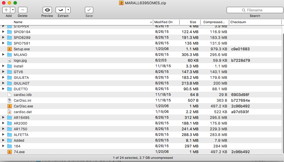
SIZE: 2.7 GB

EXCERPT:
ALFA ROMEO
3.0L V6
MANUFACTURER’S SUGGESTED SCHEDULED MAINTENANCE
The manufacturer recommends the belt be replaced every 50,000 miles.
REMOVAL & INSTALLATION
TIMING BELT
Removal
1. Disconnect negative battery cable. Raise and support vehicle. Remove right front wheel. Remove right front inner fenders. Disconnect throttle opening switch electrical connector. Remove throttle body cover.
2. Remove water pump, air conditioning, and power steering drive belts. Remove hydraulic belt tensioner.
Disconnect crankshaft position sensor connector, and remove sensor. Disconnect constant idle speed actuator electrical connector. Disconnect oil vapor separator hoses.
3. Disconnect accelerator cable. On models equipped with automatic transmission, disconnect kickdown cable. On S models, disconnect engine throttle sensor electrical connector. On all models, disconnect fuel vapor and cruise control hoses.
4. Disconnect fuel pressure regulator and power brake unit vacuum hoses. Disconnect ground strap from air intake box. Remove air intake box attaching screws and clamps, and remove air intake box.
5. Disconnect spark plug wires for cylinders No. 1, 2 and 3. Remove intake ducts and gaskets. Remove right valve cover and gasket. Disconnect spark plug wires for cylinders No. 4, 5 and 6. Remove left side valve cover and gasket.
6. Partially drain cooling system. Disconnect coolant hose from thermostat unit. Disconnect return hose from water pump. Disconnect coolant temperature switch and sensor electrical connectors. If equipped, disconnect oil cooling tubes from heat exchanger.
7. Remove timing belt covers. Remove spark plugs Rotate crankshaft so No. 1 cylinder is at TDC of compression stroke. Flywheel and transmission housing timing marks should align. See Fig. 1. Camshaft sprocket timing marks should align with bearing cap marks. See Fig. 2.
8. Lift belt tensioner arm from timing belt. Insert Holding Tool (1.820.053.00) or equivalent into hole on arm to lock in position. Loosen hydraulic belt tensioner retaining nuts. Push tensioner downward to limit of travel, and tighten upper retaining nut. Remove timing belt.
Fig. 1: Identifying Flywheel Timing Marks
Fig. 2: Identifying Camshaft Timing Marks
Installation
1. Position Adapter (1.825.007.000), or equivalent, and a dial indicator into No. 1 cylinder spark plug hole. See Fig. 2. Ensure camshaft and crankshaft timing marks align.
2. Install timing belt over crankshaft sprocket, left camshaft sprocket, right camshaft sprocket, and oil pump sprocket hydraulic belt tensioner pulley. See Fig. 3. Maintain tension on timing belt during installation.

Posted on

Alfa Romeo 4C 2013-2016 Workshop Repair & Service Manual


Download Link

INSTANT DOWNLOAD (add to cart)

SAMPLE NEW 4C MODEL

Complete digital official shop manual contains service, maintenance, and troubleshooting information for the Alfa Romeo 4C 2013-2016. Diagnostic and repair procedures are covered in great detail to repair, maintain, rebuild, refurbish or restore your vehicle like a professional mechanic in local service/repair workshop. This cost-effective quality manual is 100% complete and intact as should be without any missing pages. It is the same factory shop manual used by dealers that guaranteed to be fully functional to save your precious time.

This manual for Alfa Romeo 4C 2013-2016 is divided into different sections. Each section covers a specific component or system and, in addition to the standard service procedures, includes disassembling, inspecting, and assembling instructions. A table of contents is placed at the beginning of each section. Pages are easily found by category, and each page is expandable for great detail. It is in the cross-platform PDF document format so that it works like a charm on all kinds of devices. You do not need to be skilled with a computer to use the manual.

EXCERPT:
The Fiat Powertrain Technologies Alfa TCT is a three-shaft transmission capable of transmitting a maximum torque of 350 Nm. It uses innovative technology that allows driving comfort to be combined with an automatic transmission, with lower running costs than for manual gearboxes.
The Alfa TCT transmission is made by combining two aluminium alloy half-casings. It can be installed in front wheel drive, transverse engine layout arrangements. The Alfa TCT has a typical three-shaft layout for additional compactness. A particularity is that the main shaft actually consists of two mutually coaxial driveshafts. Two dry clutches operated by two separate hydraulic actuators are used to transmit torque to the main shaft:
a traditional one located under the transmission casing (traditional) to manage the even gear clutch;
the second one located on the transmission casing to manage the odd gear clutch.
Gears are engaged and the clutches are managed by an electro-hydraulic robot, controlled in turn by a specific transmission control unit (NCR). The electro-hydraulic robot is positioned directly on the transmission casing.

Posted on

Alexander Dennis Dart SLF, Enviro 400 Workshop Repair & Service Manual

SAMPLE Alexander Dennis Enviro 400


INSTANT DOWNLOAD


Complete digital official shop manual contains service, maintenance, and troubleshooting information for the Alexander Dennis Dart SLF (Euro3/Euro4), Enviro 400 (EURO3/EURO4&4+) Bus. Diagnostic and repair procedures are covered in great detail to repair, maintain, rebuild, refurbish or restore your vehicle like a professional mechanic in local service/repair workshop. This cost-effective quality manual is 100% complete and intact as should be without any missing pages. It is the same factory shop manual used by dealers that guaranteed to be fully functional to save your precious time.

This manual for Alexander Dennis Dart SLF (Euro3/Euro4), Enviro 400 (EURO3/EURO4&4+) Bus is divided into different sections. Each section covers a specific component or system and, in addition to the standard service procedures, includes disassembling, inspecting, and assembling instructions. A table of contents is placed at the beginning of each section. Pages are easily found by category, and each page is expandable for great detail. It is in the cross-platform PDF document format so that it works like a charm on all kinds of devices. You do not need to be skilled with a computer to use the manual.

MAKE: Alexander Dennis
MODEL: Dart SLF (Euro3/Euro4), Enviro 400 (EURO3/EURO4&4+)
FORMAT: PDF

2197:
Dart SLF Euro 3 – 4 Cylinder Parts Manual
Date: Nov 2001 (05/06); 280 pages

2209:
Dart SLF Euro 3 Service Manual
Date: Nov 2001 (01/06); 378 pages

2225:
Dart 4 & 6 cylinder/ Pointer Operation Guide
Date: September 2003 (03/04); 72 pages

2266:
Dart 4 & 6 cylinder/ Pointer Operation Guide
Date: October 2003 (08/05); 72 pages

2291:
Enviro 400 (EURO 4&4+) 4 & 6 cylinder Service Manual
Date: July 2006 (03/08); 474 pages

2292:
Enviro 400 (EURO 3) Service Manual
Date: December 2005 (03/06); 450 pages

2297:
Enviro 400 (EURO 4&4+) Service Manual
Date: March 2006 (10/07); 466 pages

2300:
Dart E4 Pointer Handbook

2301:
Dart Euro 4 Parts Manual
Covering EURO 4 CHASSIS 4-CYLINDER MODELS: SFD1HFCR56GW1, SFD1HFCR56GW9, SFD2HFCR56GW9
Publication Number: 2301 Date: October 2006

2302:
Dart SLF Euro 4 – 4 Cylinder Models Service Manual
Date: September 2006; 294 pages

EXCERPT:
Air Cleaner – Amended:

Description
The air cleaner is fitted on the nearside of the vehicle. The cleaner encloses a pleated filter element which is treated to combat premature blockage by exhaust carbon.
A remote restriction indicator is connected to the outlet to indicate clogging.

Maintenance
Access is obtained through the rear engine door. The element should be changed if the restriction indicator (fitted adjacent to the rear EDC) shows red. It is not recommended that treated elements should be washed as this removes the active chemical. In a case of necessity the element can be cleaned by blowing through with air at a max 100 p.s.i. (7 bar) in the reverse direction. To remove the element, undo the centre hand nut on the cleaner casing lid. Pull out the element and wipe out the inside of the casing with a damp cloth. Check that the gaskets are in good condition and that the casing and lid are undamaged. Fit the new element, position the lid and tighten the hand nut. If necessary reset the restriction indicator by pressing down on the top.

Vehicle checks
After reassembly but before restarting engine, the following system checks must be carried out.
a. Check all cleaner to engine pipe work for defects to ensure good and leak free condition.
b. Check that all rubber hose connections are tight and leak free. Renew any worn or damaged parts.
c. Check that the cleaner mounting fixtures are secure.

Restriction Indicator
The restriction indicator gives a warning that the air cleaner filter is too clogged for further service. The indicator is operated by the depression between the air cleaner and the engine, and at a preset figure, the red warning indicator will remain locked up in a visible position after the engine has stopped running.
When the red indicator band appears, the air cleaner element must be removed and renewed. After the element has been renewed, reset the indicator by pushing on the diaphragm at the top of the instrument. Blank off the connection if the indicator is not fitted.


INSTANT DOWNLOAD


Posted on

Acura ZDX 2010-2013 Workshop Repair & Service Manual

Sample Acura-ZDX ENGINE Cylinder Head

MACRZDX1013NPES.PDF
Price: $19.99 USD

Complete digital official shop manual contains service, maintenance, and troubleshooting information for the Acura ZDX 2010-2013. Diagnostic and repair procedures are covered in great detail to repair, maintain, rebuild, refurbish or restore your vehicle like a professional mechanic in local service/repair workshop. This cost-effective quality manual is 100% complete and intact as should be without any missing pages. It is the same factory shop manual used by dealers that guaranteed to be fully functional to save your precious time.

This manual for Acura ZDX 2010-2013 is divided into different sections. Each section covers a specific component or system and, in addition to the standard service procedures, includes disassembling, inspecting, and assembling instructions. A table of contents is placed at the beginning of each section. Pages are easily found by category, and each page is expandable for great detail. It is in the cross-platform PDF document format so that it works like a charm on all kinds of devices. You do not need to be skilled with a computer to use the manual.

FILELIST:
ACCESSORIES & EQUIPMENT AcuraLInk.pdf
ACCESSORIES & EQUIPMENT Adaptive Cruise Control (ACC).pdf
ACCESSORIES & EQUIPMENT Audio System.pdf
ACCESSORIES & EQUIPMENT Audio, Navigation and Telematics (Special Tools).pdf
ACCESSORIES & EQUIPMENT Automatic Dimming Inside Mirror.pdf
ACCESSORIES & EQUIPMENT Blind Spot Information System (BSI).pdf
ACCESSORIES & EQUIPMENT Body (Special Tools).pdf
ACCESSORIES & EQUIPMENT Body-Panoramic Glass Roof.pdf
ACCESSORIES & EQUIPMENT Bumpers.pdf
ACCESSORIES & EQUIPMENT Consoles.pdf
ACCESSORIES & EQUIPMENT Cruise Control.pdf
ACCESSORIES & EQUIPMENT Dashboard.pdf
ACCESSORIES & EQUIPMENT Dashlights Brightness Controller.pdf
ACCESSORIES & EQUIPMENT Doors.pdf
ACCESSORIES & EQUIPMENT Driver Position Memory System (DPMS).pdf
ACCESSORIES & EQUIPMENT Entry Lights Control System.pdf
ACCESSORIES & EQUIPMENT Exterior Lights.pdf
ACCESSORIES & EQUIPMENT Exterior Trim.pdf
ACCESSORIES & EQUIPMENT Fenderwell.pdf
ACCESSORIES & EQUIPMENT Frame.pdf
ACCESSORIES & EQUIPMENT Fuel Fill Door.pdf
ACCESSORIES & EQUIPMENT Gauges.pdf
ACCESSORIES & EQUIPMENT Glass.pdf
ACCESSORIES & EQUIPMENT HandsFreeLink System.pdf
ACCESSORIES & EQUIPMENT HomeLink Remote Control System.pdf
ACCESSORIES & EQUIPMENT Hood.pdf
ACCESSORIES & EQUIPMENT Horns.pdf
ACCESSORIES & EQUIPMENT Ignition Switch.pdf
ACCESSORIES & EQUIPMENT Immobilizer System.pdf
ACCESSORIES & EQUIPMENT Interior Lights.pdf
ACCESSORIES & EQUIPMENT Interior Trim.pdf
ACCESSORIES & EQUIPMENT Keyless Access System.pdf
ACCESSORIES & EQUIPMENT KeylessPower Door LocksSecurity System.pdf
ACCESSORIES & EQUIPMENT Mirrors.pdf
ACCESSORIES & EQUIPMENT Multiplex Integrated Control System.pdf
ACCESSORIES & EQUIPMENT Navigation System.pdf
ACCESSORIES & EQUIPMENT Panoramic Glass Roof.pdf
ACCESSORIES & EQUIPMENT Power Lumbar Support.pdf
ACCESSORIES & EQUIPMENT Power Mirrors.pdf
ACCESSORIES & EQUIPMENT Power Seats.pdf
ACCESSORIES & EQUIPMENT Power Tailgate.pdf
ACCESSORIES & EQUIPMENT Power Windows.pdf
ACCESSORIES & EQUIPMENT Rear Window Defogger.pdf
ACCESSORIES & EQUIPMENT Rearview Mirror With Rearview Camera Display.pdf
ACCESSORIES & EQUIPMENT Reminder Systems.pdf
ACCESSORIES & EQUIPMENT Safety Indicator System.pdf
ACCESSORIES & EQUIPMENT Seat Heaters.pdf
ACCESSORIES & EQUIPMENT Seats.pdf
ACCESSORIES & EQUIPMENT Tailgate.pdf
ACCESSORIES & EQUIPMENT Turn SignalHazard Warning Lights.pdf
ACCESSORIES & EQUIPMENT Ventilated Seats.pdf
ACCESSORIES & EQUIPMENT Wiper System Washer System.pdf
BRAKES Collision Mitigation Braking System (CMBS).pdf
BRAKES Conventional Brake System.pdf
BRAKES VSA System Components.pdf
CABIN AIR FILTER.pdf
DRIVELINEAXLES DrivelineAxle.pdf
DRIVELINEAXLES Rear Differential.pdf
ELECTRICAL Accessory Power Sockets.pdf
ELECTRICAL Battery Management System.pdf
ELECTRICAL Battery.pdf
ELECTRICAL Body Electrical (Special Tools.pdf
ELECTRICAL Charging System.pdf
ELECTRICAL Connectors and Harnesses.pdf
ELECTRICAL Engine Electrical (Special Tools).pdf
ELECTRICAL FuseRelay Boxes.pdf
ELECTRICAL Ground Distribution.pdf
ELECTRICAL OEM Wiring Diagram General Information.pdf
ELECTRICAL Power Distribution (Fuse ID).pdf
ELECTRICAL Relay and Control Unit Locations.pdf
ELECTRICAL Relays.pdf
ELECTRICAL Under-Dash FuseRelay Box.pdf
ELECTRICAL Under-Hood FuseRelay Box.pdf
ENGINE Cooling System.pdf
ENGINE Cylinder Head.pdf
ENGINE Engine Assembly.pdf
ENGINE Engine Block.pdf
ENGINE Engine Lubrication.pdf
ENGINE Engine Mount Control System.pdf
ENGINE Fan Controls.pdf
ENGINE Ignition System.pdf
ENGINE Intake Manifold and Exhaust System.pdf
ENGINE PERFORMANCE Advanced Diagnostics.pdf
ENGINE PERFORMANCE Catalytic Converter System-.pdf
ENGINE PERFORMANCE Catalytic Converter System.pdf
ENGINE PERFORMANCE Communication Systems (F-CAN, K-LINE).pdf
ENGINE PERFORMANCE EGR System.pdf
ENGINE PERFORMANCE Electronic Throttle Control System.pdf
ENGINE PERFORMANCE EVAP System.pdf
ENGINE PERFORMANCE Fuel and Emissions Systems.pdf
ENGINE PERFORMANCE Fuel Supply System.pdf
ENGINE PERFORMANCE Idle Control System.pdf
ENGINE PERFORMANCE IMT System.pdf
ENGINE PERFORMANCE Mode 6.pdf
ENGINE PERFORMANCE PCV System.pdf
ENGINE PERFORMANCE PGM-FI System.pdf
ENGINE PERFORMANCE VTEC.pdf
ENGINE Starting System—.pdf
ENGINE Starting System.pdf
FIRING ORDER & CYLINDER IDENTIFICATION Firing Order & Cylinder Identification.pdf
GENERAL INFO Battery Cable Reset.pdf
GENERAL INFORMATION General Information.pdf
GENERAL INFORMATION Specifications.pdf
GENERAL INFORMATION Symptom Check List Worksheets.pdf
GENERAL INFORMATION Trouble Shooting – Basic Procedures.pdf
HVAC Climate Control.pdf
HVAC HVAC (Special Tools).pdf
MAINTENANCE Maintenance.pdf
REMINDER INDICATOR RESET PROCEDURES.pdf
RESTRAINTS Restraints (Special Tools).pdf
RESTRAINTS Seat Belts.pdf
RESTRAINTS SRS (Supplemental Restraint System).pdf
STEERING Electronic Power Steering (EPS) System.pdf
STEERING Hydraulic Power Steering Components.pdf
STEERING Power Steering System.pdf
SUSPENSION Active Damper System.pdf
SUSPENSION ACURA WHEEL ALIGNMENT SPECIFICATIONS.pdf
SUSPENSION Front and Rear Suspension (Inspection).pdf
SUSPENSION Front Suspension.pdf
SUSPENSION Rear Suspension.pdf
SUSPENSION TPMS (Tire Pressure Monitoring System).pdf
SYSTEM WIRING DIAGRAMS 1.pdf
SYSTEM WIRING DIAGRAMS 2.pdf
TIRE PRESSURE MONITOR SYSTEMS.pdf
TRANSMISSION Automatic Transmission.pdf

EXCERPT:
Acura ZDX – 2012 ENGINE Engine Block – ZDX

CRANKSHAFT MAIN BEARING REPLACEMENT
MAIN BEARING CLEARANCE INSPECTION
1. Remove the main bearing caps and the bearing halves (see CRANKSHAFT AND PISTON REMOVAL ).
2. Clean each main journal and bearing half with a clean shop towel.
3. Place one strip of plastigage across each main journal.
4. Reinstall the bearings and the main bearing caps, then torque the bearing cap bolts to 74 N.m (7.5 kgf.m, 55 lbf.ft), and the bearing cap side bolts to 49 N.m (5.0 kgf.m, 36 lbf.ft) in the proper sequence (see step 22 ).
5. Remove the main bearing cap and the bearing half, and measure the widest part of the plastigage. Main Bearing-to-Journal Oil Clearance Standard (New): 0.019-0.045 mm (0.00075-0.00177 in)
Service Limit: 0.050 mm (0.00197 in)
Fig. 7: Checking Main Bearing-To-Journal Oil Clearance
6. If the plastigage measures too wide or too narrow, remove the crankshaft, and remove the upper half of the bearing. Install a new, complete bearing with the same color code, and recheck the clearance. Do not file, shim, or scrape the bearings or the caps to adjust clearance.
7. If the plastigage shows the clearance is still incorrect, try the next larger or smaller bearing (the color listed above or below that one), and check the clearance again. If the proper clearance cannot be obtained by using the appropriate larger or smaller bearings, replace the crankshaft and start over (see CRANKSHAFT AND PISTON REMOVAL ).

MAIN BEARING SELECTION
Block Bore Code Locations
Letters or bars have been stamped on the end of the engine block as a code for the size of each of the four main journal bores.
Use them, and the numbers or bars stamped on the crankshaft (codes for main journal size), to choose the correct bearings. If the codes are indecipherable because of an accumulation of dirt and dust, do not scrub them with a wire brush or scraper. Clean them only with solvent or detergent.
Fig. 8: Identifying Block Bore Code Locations
Fig. 9: Bearing Color Code Chart
Main Journal Code Locations (Numbers or Bars)
Fig. 10: Identifying Main Journal Code Locations (Numbers And Bars)

CONNECTING ROD BEARING REPLACEMENT
CONNECTING ROD BEARING CLEARANCE INSPECTION
1. Remove the connecting rod cap and the bearing half (see CRANKSHAFT AND PISTON
REMOVAL ).
2. Clean the connecting rod journal and the bearing half with a clean shop towel.
3. Place a strip of plastigage across the connecting rod journal.
4. Reinstall the bearing half and the connecting rod cap, and torque the connecting rod bolt to 20 N.m (2.0 kgf.m, 15 lbf.ft) + 90°.

Posted on

Acura SLX 1996-1999 Workshop Repair & Service Manual

Acura SLX 1996-1999 Preview

MACRSLX9699NPES.PDF
Price: $19.99 USD

Complete digital official shop manual contains service, maintenance, and troubleshooting information for the Acura SLX 1996-1999. Diagnostic and repair procedures are covered in great detail to repair, maintain, rebuild, refurbish or restore your vehicle like a professional mechanic in local service/repair workshop. This cost-effective quality manual is 100% complete and intact as should be without any missing pages. It is the same factory shop manual used by dealers that guaranteed to be fully functional to save your precious time.

This manual for Acura SLX 1996-1999 is divided into different sections. Each section covers a specific component or system and, in addition to the standard service procedures, includes disassembling, inspecting, and assembling instructions. A table of contents is placed at the beginning of each section. Pages are easily found by category, and each page is expandable for great detail. It is in the cross-platform PDF document format so that it works like a charm on all kinds of devices. You do not need to be skilled with a computer to use the manual.

MAKE: Acura 1996-1999
— — — — — — — — —
MODEL: SLX
— — — — — — — — —
YEAR: 1996, 1997, 1998, 1999

EXCERPT:
1999-2001 ENGINES 3.2L & 3.5L V6
EXHAUST MANIFOLD
Removal & Installation
Disconnect negative battery cable. On right manifold, remove torsion bar. On left manifold, disconnect O2 sensor connector. On both manifolds, remove front exhaust pipe. On right manifold, remove EGR pipe bolts and gasket from exhaust manifold. On both manifolds, remove exhaust manifold heat shield. Remove exhaust manifolds from engine. To install, reverse removal procedure. Tighten bolts and nuts to specification. See TORQUE SPECIFICATIONS.
CYLINDER HEAD COVERS
Removal & Installation (3.2L – Left Side)
1. Disconnect negative battery cable. Remove air cleaner and duct assembly. Disconnect PCV hose.
Disconnect camshaft angle sensor connector.
2. Remove ground cable bolt from cylinder head cover. Remove ignition coils. Remove fuel injector harness bracket bolt. Remove 8 cylinder head cover bolts and cylinder head cover.
3. To install, apply RTV sealant to corners of end camshaft bearing towers. To complete installation, reverse removal procedure. Tighten bolts to specification. See TORQUE SPECIFICATIONS.
Removal & Installation (3.2L – Right Side)
1. Disconnect negative battery cable. Disconnect ventilation hose from cylinder head cover. Remove ignition coils. Remove heater pipe bolts from bracket. Disconnect fuel injector harness connector, then remove fuel injector harness bracket bolt.
2. Remove EGR pipe flare nut from EGR valve. Remove EGR pipe bracket bolt from rear of cylinder head.
Remove 2 EGR pipe bolts and nut from exhaust manifold. Remove EGR pipe. Remove 8 cylinder head cover bolts and cylinder head cover.
3. To install, apply RTV sealant to corners of end camshaft bearing towers. To complete installation, reverse removal procedure. Tighten bolts to specification. See TORQUE SPECIFICATIONS.
Removal (1999 3.5L – Left Side)
1. Disconnect battery ground cable. Drain engine coolant from radiator. Remove engine cover from dowels on common chamber. Remove air cleaner duct assembly and air cleaner element.
NOTE: Disconnect Mass Airflow (MAF) sensor connector, Intake Air Temperature
(IAT) sensor connector, and PCV hose before air cleaner duct assembly is removed.
2. Disconnect following wiring connectors and bonding cable:
 Manifold Absolute Pressure (MAP) sensor.
 Vacuum Switching Valve (VSV) for Induction Air Control Valve (IACV) actuator.
 Ignition coils for left bank.
 Fuel injectors for left bank.
 Idle air control (IAC) valve.
 Throttle position sensor (TPS).
 Bonding cable.
 Others as necessitated.
3. Disconnect following vacuum hoses:
 Brake master VAC
 Canister
 VSV for IACV actuator
 Duty solenoid valve
 PCV
4. Disconnect radiator upper and lower hoses. Remove engine harness from cylinder head cover. Remove upper fan guide. Remove cooling fan and clutch assembly. Remove drive belt by rotating auto tensioner
clockwise.
5. Remove power steering oil pump pulley. Remove fan pulley and bracket assembly. Remove idle pulley assembly. Remove auto tensioner assembly. Remove crankshaft pulley using Crankshaft Holder (J-8614-
01).
6. Remove timing belt covers from right bank side and left bank side in that order. Remove ignition coil assemblies for the left side bank. Remove cylinder head cover assembly.
Removal (1999 3.5L – Right Side)
1. Disconnect battery cables, and remove battery. Drain engine coolant from radiator. Remove engine cover from dowels on common chamber. Remove air cleaner duct assembly and air cleaner element.
2. Disconnect following wiring connectors and ground cable:
 EGR valve.
 Fuel injectors for right bank.
 Ignition coils for right bank.
 Ground cable.
 Others as necessitated.