Posted on

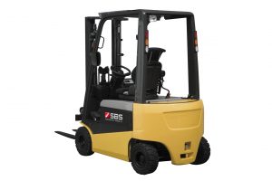
Atlet Forklift Trucks 2008-2011 Workshop Repair & Service Manual

Atlet Forklift Trucks 2008-2011 Workshop Repair & Service Manual

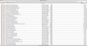
SAMPLE Atlet 2008-2011

MATL0811OPES.PDF
Price: $29.99 USD

Complete digital official shop manual contains service, maintenance, and troubleshooting information for the Atlet Forklift Trucks 2008-2011. Diagnostic and repair procedures are covered in great detail to repair, maintain, rebuild, refurbish or restore your vehicle like a professional mechanic in local service/repair workshop. This cost-effective quality manual is 100% complete and intact as should be without any missing pages. It is the same factory shop manual used by dealers that guaranteed to be fully functional to save your precious time.

This manual for Atlet Forklift Trucks 2008-2011 is divided into different sections. Each section covers a specific component or system and, in addition to the standard service procedures, includes disassembling, inspecting, and assembling instructions. A table of contents is placed at the beginning of each section. Pages are easily found by category, and each page is expandable for great detail. It is in the cross-platform PDF document format so that it works like a charm on all kinds of devices. You do not need to be skilled with a computer to use the manual.

MAKE: Atlet
MODEL: T / A / X / U / O / P Chassis
FORMAT: PDF
SIZE: 435 MB
LANGUAGE: English / German / French / Swedish

MAKE: Atlet
MODEL: T / A / X / U / O / P Chassis
FORMAT: PDF
SIZE: 484 MB
LANGUAGE: English / German / French / Swedish

Atlet Forklift Trucks Spare Parts Catalog, Service Manual, and Electrical Diagrams

├── T Chassis
│   ├── TLL / TLP
│   ├── TP
│   ├── TS
├── A Chassis
│   ├── A
│   ├── A-Ergo
├── X Chassis
│   ├── X-90
│   ├── X-Ergo
├── U Chassis
│   ├── UNN
│   ├── URF AC (Powder Plus)
│   ├── U*S AC (Powder Plus)
│   ├── U-TERGO
├── O Chassis
├── P Chassis
│   ├── PLL
│   ├── PLP
│   ├── PP
│   ├── PS

BONUS.MATERIAL:
Warehouse 2008B (PDF, 49 MB)
A-Ergo
OP
PLL-PSD-PSL-PLE
PLP
PP
PS
T
U
X-Ergo

Atlet (Eden Farm) (PDF, 12 MB)
Electrical Diagrams
U Tergo
UNS_UHS

EXCERPT:
7.2.2.4 Operation test of steering servo system – fly by wire
1. Log on the truck and check that the operation of the end stops in both directions is correct.
2. Turn the mini wheel clockwise to the maximum. Connect the red/black cable with the pink/black cable coming from X18’s connection closest to the servo box. Turn the steering to the centre position. After approx. 10 mm of movement on the gearbox the servo contactor should open. Check that the brakes are properly applied and that it is not possible to drive the machine. If
the brakes are not on and the machine can be driven then the circuit must be checked. The drive controller E1 is supplied from the servo contact E4 pin 8.
Check that pin 8 is not live, if it is – replace the servo box. Reset using the off-on buttons on the keyboard.
3. Brown/white cable. Perform the equivalent procedure with the switch by connecting together the red/black cable with the brown/white cable.
4. Pull apart the connector P14 (tied to the return hose on UNS). The servo contactor should open and it should be impossible to release the brake; it should also be impossible to drive the truck. Connect P14 again.
5. Pull out the motor fuse for the servo motor (F4). The servo motor should
open and it should be impossible to release the brake; it should also be impossible to drive the truck. Fit the fuse again.
6. If it is possible to release the brake after points 2, 3, 4 or 5 have been implemented, or it is possible to drive the truck, the truck must be checked carefully and not used until the fault has been rectified.
7. Finally check that the drive unit does not hit the mechanical stop in the end
positions.

7.2.2.5 Mechanical adjustment to the steering sensors – EPS 2001/ EPS AC0
With the gear box on the seat side of the truck, turn the drive wheel anticlockwise a little over +90 degrees (Circa +100 degrees) ensuring that the cam on the drive unit is located under both threaded holes for the sensors.
Screw in the sensor (follow with the cable to avoid twisting) until it reaches the bottom on the cam. Then unscrew the sensor a 3/4 turn and lock the sensor with the nut.
Important!
The nut is to be locked using thread locking solution. However, make sure that the thread locking solution is not applied in the threaded hole.

7.2.2.6 Operation test of the steering sensors – EPS 2001/EPS AC0
1. With the gear box on the seat side of the truck, turn the drive wheel anticlockwise a little over +90 degrees (Circa +100 degrees) ensuring that the cam on the drive unit is located under both threaded holes for the sensors.
2. Switch off the truck.
3. Disconnect the cable to the steering sensor.
4. Unscrew the steering sensor (follow with the cable to avoid twisting).
5. Reconnect the cable.
6. Start the truck and log on.
7. Hold the sensor top against some metal (iron, steel, etc).
8. Make sure that the sensor has the correct status by checking the menu “Logged on service”:
9. The steering sensor must be active when metal comes within about 2 mm of the sensor top.
10. Reinstall the sensor as described in section 7.2.2.5.

Posted on

Aston Martin DB9 2004-2016 Factory Service & Shop Manual

Pages from 4G43-43-10032 – Aston Martin DB9 Workshop Manual (Issue 7)

MASMADB9OPEK.PDF
Price: $29.99 USD

Complete workshop & service manual with electrical wiring diagrams for Aston Martin DB9 2004-2016. It’s the same service manual used by dealers that guaranteed to be fully functional and intact without any missing page.

This Aston Martin DB9 2004-2016 service & repair manual (including maintenance, overhaul, disassembling & assembling, adjustment, tune-up, operation, inspecting, diagnostic & troubleshooting…) is divided into different sections. Each section covers a specific component or system with detailed illustrations. A table of contents is placed at the beginning of each section. Pages are easily found by category, and each page is expandable for great detail. The printer-ready PDF documents work like a charm on all kinds of devices.

4G43-43-10032 – Aston Martin DB9 Workshop Manual (Issue 7).pdf

EXCERPT:
DB9 Workshop Manual
Contents
Introduction
Welcome…….. i-i-iv
Safety Precautions……. i-i-v
Lifting and Jacking………….. i-i-vii
Vehicle Recovery ……………i-i-viii
Vehicle Identification Number ……. i-i-ix
Body System (01.00)
Body Structure (01.01) …….1-1-3
Front End System (01.02) …………..1-2-1
Body Closures (01.03)……..1-3-1
Interior Trim (01.05) ……….1-5-1
Exterior Trim (01.08)……….1-8-1
Mirrors (01.09)……..1-9-1
Seating (01.10)……..1-10-1
Glass, Frame and Mechanism (01.11)…….1-11-1
Instrument Panel (IP) (01.12)…….1-12-1
Handles and Lock Mechanisms (01.14) ………….1-14-1
Wipers and Washer System (01.16)……..1-16-1
Bumpers (01.19) …………..1-19-1
Restraining Devices (01.20)………1-20-1
Frame and Mounting (02.00)
Subframes (02.03)…………..2-1-2
Engine System (03.00)
Engine Assembly (03.00) ……………3-0-3
Engine Structure (03.01)…….3-1-1
Lubrication System (03.02)…………3-2-1
Cooling System (03.03) ……..3-3-1
Fuel Charging System (03.04) ……..3-4-1
Accessory Drive System (03.05)…….3-5-1
Engine Cranking System (03.06) ……………3-6-1
Ignition System (03.07) ……..3-7-1
Emission Control (03.08) ……………3-8-1
Valve Train (03.09) …………3-9-1
Engine Sealing (03.10)……..3-10-1
Power Conversion (03.11)………..3-11-1
Air Charging (03.12)………3-12-1
Evaporative Emissions (03.13) …….3-13-1
Engine Management System (03.14)…….3-14-1
Throttle Control (03.16) …………..3-16-1
Suspension (04.00)
Road Wheel Alignment (04.00) …….4-0-2
Front Suspension (04.01)……………4-1-1
Rear Suspension (04.02)…….4-2-1
Road Wheels and Tyres (04.04) ……………4-4-1
Driveline (05.00)
Driveshaft (05.01) …………..5-1-2
Rear Drive System (05.02) …………5-2-1
Halfshafts (05.05)……………5-5-1
Brake System (06.00)
Description………….6-1-2
Front Disc Brake (06.03) ……………6-3-1
Rear Disc Brakes (06.04)……………6-4-1
Hand Brake (06.05) ………..6-5-1
Brake Actuation System (06.06) ……………6-6-1
Power Brake System (06.09) ………6-9-1
Transmission (07.00)
Automatic Transmission (07.01) ……………7-1-2
Transmission Cooling (07.02) ……..7-2-1
Manual Transmission (07.03) ……..7-3-1
Automatic Control System (07.05)…………7-5-1
Clutch (08.00)
Clutch Controls (08.02)……..8-2-1
Exhaust (09.00)
Exhaust Overview …………..9-1-2
Silencer Assembly (09.01) ………….9-1-3
Pipes and Supports (09.03) ………..9-3-1
Fuel (10.00)
Fuel Tank and Lines (10.01)……..10-1-2
Steering (11.00)
Steering Gear (11.01)…….11-1-2
Power Steering (11.02)…….11-2-1
Steering Column (11.04) ………….11-4-1
Steering Column Switches (11.05)……….11-5-1
Steering Wheel (11.06) ……………11-6-1
Climate Control (12.00)
Body Ventilation system (12.01)………….12-1-3
Heater System (12.02) …….12-2-1
Air Conditioning (A/C) System (12.03) ……………12-3-1
A/C Control System (12.04)………12-4-1
Information, Gauge and Warning (13.00)
Instrument Cluster (13.01) ……….13-1-2
Power Supply (14.00)
Battery System (14.01) …….14-1-2
Alternator and Regulator System (14.02) ………..14-2-1
Vehicle Entertainment (15.00)
Audio System ……. 15-1-1
Vacuum Distribution (16.00)
Body Vacuum System (16.01)……. 16-1-1
Lighting (17.00)
Front Lights (17.01) ……… 17-1-2
Interior Lighting (17.02)………….. 17-2-1
Rear Lights (17.03) ………. 17-3-1
Lighting Mechanisms (17.04) …….. 17-4-1
Electric Distribution/Electronic Control (18.00)
Wiring and Circuit Protection (18.01) …………… 18-1-2
Vehicle Control System (18.08) …………. 18-8-1
Electronic Features (19.00)
Active Anti-Theft System (19.01)………… 19-1-2
Navigation (19.07)……….. 19-7-1
Appendix & Glossary
Diagnostic Ports……. 20-1-2
Fluids/Capacities…………… 20-1-3
Abbreviations …….. 20-1-3
Terms……… 20-1-3
Special Tools – Pictorial Index…….. 20-1-4
Specialist Tool Operation ………… 20-1-8
Maintenance Schedules…………. 20-1-11
Torque Figures …………… 20-1-14
Torque Conversion Tables ……… 20-1-31
….
Brake Systems (06.00)
Hand Brake (06.05)
Description
The hand brake control lever is installed at the outer side of the driver’s seat. When the lever is operated, a cable applies mechanical brakes to each rear wheel. Each mechanical caliper applies brake pads to a brake disc installed on each rear road wheel hub. The calipers are bolted to the vertical links. When the parking brake is released, the pads are retracted by springs. Each caliper has a mechanism that automatically adjusts for wear in the pads. There are adjusters to tension the cable if it stretches.
There is a switch installed on the lever assembly that has contacts that are normally closed. When the handbrake is off, the contacts in the switch are open. The contacts close when the handbrake is applied. This causes the hand brake warning light in the instrument panel to come on.

Posted on

Aprilia Motorcycles Factory Service & Shop Manual

MAPRMISCOPEK.PDF.zip
Price: $19.99 USD

Complete workshop & service manual with electrical wiring diagrams for Aprilia Atlantic 125-200-250-500 Sprint, SRV 850, NA 850 Mana, Dorsoduro, Dorsoduro 750 F, RS 125, Tuono 1000, RST Mille, RST Mille Futura, RSV mille, SR 50, SR 50 TE, ETV Mille, ETV Mille Rally, Leonardo 120-154-250-300, Scarabeo 120S-154S-500, Mojito 50-125-150, RS4 125, RS 125-250, Pegaso 650, Pegaso 650 Strada, Sportcity 125, Sportcity 250 i.e.. It’s the same service manual used by dealers that guaranteed to be fully functional and intact without any missing page.

This Aprilia Motorcycles Atlantic 125-200-250-500 Sprint, SRV 850, NA 850 Mana, Dorsoduro, Dorsoduro 750 F, RS 125, Tuono 1000, RST Mille, RST Mille Futura, RSV mille, SR 50, SR 50 TE, ETV Mille, ETV Mille Rally, Leonardo 120-154-250-300, Scarabeo 120S-154S-500, Mojito 50-125-150, RS4 125, RS 125-250, Pegaso 650, Pegaso 650 Strada, Sportcity 125, Sportcity 250 i.e. service & repair manual (including maintenance, overhaul, disassembling & assembling, adjustment, tune-up, operation, inspecting, diagnostic & troubleshooting…) is divided into different sections. Each section covers a specific component or system with detailed illustrations. A table of contents is placed at the beginning of each section. Pages are easily found by category, and each page is expandable for great detail. The printer-ready PDF documents work like a charm on all kinds of devices.

970MB PDF
FILELIST:
1095 2 – Aprilia Ditech Engine Electronic Air Injection Quick Workshop Handbook.pdf
677617 EN – SRV 850 SRV 850 ABS – ATC Service Station Manual.pdf
854007 – Atlantic 250 i.e. Owner’s Manual.pdf
854171 – NA 850 Mana Service Station Manual.pdf
854251 – Dorsoduro ABS Service Station Manual.pdf
895785 – Dorsoduro Factory Service Station Manual.pdf
8102474 RX 125 Use & Maintenance Book (IT).pdf
8102710 – Moto 6.5 Use & Maintenance.pdf
8102759 – Pegaso 650 Use & Maintenance Manual.pdf
8104065 – Pegaso 650 USA Use & Maintenance Manual.pdf
8104163 – RST Mille Futura Use & Maintenance Book.pdf
8104269 – RSV mille – RSV mille R Use & Maintenance Book.pdf
8104312 – Pegaso 650 I.E. Use & Maintenance Manual.pdf
8104468 – RS 125 Use & Maintenance Manual.pdf
8104553 – 125 – 150 – 250 Use & Maintenance Book.pdf
8104675 – Atlantic 125 – 200 Use & Maintenance Book.pdf
8104713 – QUASAR 125-180 Use & Maintenance Book.pdf
8104928 – RSV 1000 Tuono R Use & Maintenance Book.pdf
8104936 – Pegaso 650 Strada – Trail Use & Maintenance Manual.pdf
8104976 – RS 125 Workshop Manual.pdf
8104982 – Tuono 1000 Workshop Manual.pdf
8140134 – Engine 122 (ROTAX) Workshop Manual.pdf
8140139 – Engine 655_97, 655 EFI Repair Manual.pdf
8140172 – RSV mille Service and Repair Manual.pdf
8140212 – SR 50 Service & Repair Manual.pdf
8140240 – Engine AM6 (970X) Workshop Manual.pdf
8140246 – Engine MA 50, MY 50 Workshop Manual.pdf
8140279 – Motor 125_150 2T Manuale d’officina (IT).pdf
8140291 – 120-154 Leonardo, 120S-154S Scarabeo (Rotax) Workshop Manual.pdf
8140542 – RST Mille Workshop Manual.pdf
8140548 – ETV Mille Workshop Manual.pdf
8140586 – Engine V990 Workshop Manual.pdf
8140587 – Engine V990 Workshop Manual.pdf
8140632 – Atlantic 500 Workshop Manual.pdf
8140638 – Atlantic 500 Workshop Manual.pdf
8140674 – Atlantic 125 – 200 Workshop Manual.pdf
8140687 – RSV Mille Workshop Manual.pdf
8140688 – RSV Mille Workshop Manual.pdf
8140754 – Mojito 50 – 125 – 150 Workshop Manual.pdf
8140782 – Leonardo 250 – 300 Workshop Manual.pdf
8140787 – Engines 3AS – 4AS Workshop Manual.pdf
8140811 – Sportcity 125 – 200 Workshop Manual.pdf
8140816 – SR 50 Workshop Manual.pdf
8140817 – SR 50 Workshop Manual.pdf
8140822 – Engine C361M, C364M, C216M Workshop Manual.pdf
8140866 – Atlantic – 125 – 200 – 250 – 500 Sprint Workshop Manual.pdf
8140963 – Pegaso 650 Strada – Trail Workshop Manual.pdf
8181011 – Atlantic – 125 – 250 – 500 Sprint Use + Maintenance Book.pdf
8181024 – Scarabeo 500 Workshop Manual.pdf
8202351 – Rally 50 Use & Maintenance Book.pdf
8202412 – RS 50 Use & Maintenance Manual.pdf
8202427 – QUASAR 50-100-125-180 Use & Maintenance Book.pdf
AP8181026 – Sportcity 250 i.e. Service Station Manual.pdf
Aprilia Engine 50 cc Quick Workshop Handbook.pdf
Aprilia Engine 122 (Rotax) Repair Manual.pdf
Aprilia Engine 655_95 (BRP Rotax 655) Repair Manual.pdf
Aprilia Engine 655_95 Repair Manual.pdf
Aprilia Engine MY 660 Service Manual.pdf
Aprilia Motor YP 250 4T Quick Workshop Handbook.pdf
B043126 – RS4 125 Service Station Manual.pdf
Dorsoduro 750 Factory – ABS 2010-2013 Spare Parts Catalog.pdf
ETV 1000 Caponord Use & Maintenance.pdf
ETV mille Rally Repair manual ’03-’04 Update.pdf
Leonardo 125 Service & Repair Manual.pdf
NSG5000U01 – SR 50 – 125 – 150 Use & Maintenance Book.pdf
NSG5000U01 – SRV 850 4T 8V E3 2012-2013 Spare Parts Catalogue.pdf
Pegaso 650 (942V) Service & Repair Manual.pdf
Pegaso 650 Service & Repair Manual.pdf
Pegaso 650 Service Manual.pdf
RS 125 MY 07 (EURO 3) Wiring Diagram.pdf
RS 125 Tuono Workshop Manual Update.pdf
RS 125 Workshop Manual.pdf
RS 250 Service & Repair Manual.pdf
RS 250 Workshop Manual.pdf
RS4 125 4T 2011-2013 Spare Parts Catalog.pdf
RST Mille Futura Workshop Manual.pdf
RSV 1000 Technical Training Course – RSV Mille.pdf
RSV Mille Parts list.pdf
RSV4 Factory – R Owner’s Manual.pdf
Scarabeo 50 2T Owner’s Manual.pdf
SR 50 TE (Engine C361M, Engine C364M) Service Manual Update.pdf
SXV_RXV 450-550 Use & Maintenance Book.pdf

Posted on

Allison Transmission 1000/2000/3000/4000 Product Families Factory Service & Shop Manual

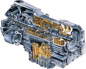
SAMPLE – Allison Transmission 1000/2000/3000/4000 Product Families Factory Service & Shop Manual


INSTANT DOWNLOAD


Complete workshop & service manual with bonus troubleshooting manuals for Allison Transmission 1000/2000/3000/4000 Product Families. It’s the same service manual used by dealers that guaranteed to be fully functional and intact without any missing page.

This Allison Transmission 1000/2000/3000/4000 Product Families service & repair manual (including maintenance, overhaul, disassembling & assembling, adjustment, tune-up, operation, inspecting, diagnostic & troubleshooting…) is divided into different sections. Each section covers a specific component or system with detailed illustrations. A table of contents is placed at the beginning of each section. Pages are easily found by category, and each page is expandable for great detail. The printer-ready PDF documents work like a charm on all kinds of devices.

FILELIST:
“GN4008EN.pdf”
Allison Transmission Allison 4th Generation Controls (1000 Product Family, 2000 Product Family) In-Chassis Maintenance; 2007 JANUARY; GN4008EN

“JA3664EN.pdf”
Allison Transmission VOCATIONAL MODELS In-Chassis Maintenance; 2004 APRIL 01; JA3664EN
1000 EVS, 1000 HS, 1000 MH, 1000 PTS, 1000 RDS, 1000 SP, B 210, 2100 EVS, 2100 HS, 2100 MH, 2100 PTS, 2100 RDS, 2100 SP, B 220, 2200 EVS, 2200 HS, 2200 MH, 2200 PTS, 2200 RDS, 2200 SP, 2500 EVS, 2500 HS, 2500 MH, 2500 PTS, 2500 RDS, 2500 SP
1000 Series, 2000 Series, 2000 MH Series, 2400 Series

“MT4015EN.pdf”
Allison 4th Generation Controls – 3000 Product Family (Except 3700 SP), 4000 Product Family Mechanic’s Tips; 2005 FEBRUARY, Rev. 1 2005 SEPTEMBER; MT4015EN

“OM3349EN.pdf”
Motorhome Series 3000/4000 Operator’s Manual; 2005/09
Allison Transmission VOCATIONAL MODELS Motorhome Series (MH) Transmissions
3000 and 4000 Product Families
WTEC III Controls and Allison 4th Generation Controls
3000 MH, 4000 MH

“OM4118EN.pdf”
Allison Transmission 1000 & 2000 Product Families International Models Operator’s Manual; 2005/09
Includes Allison 4th Generation Controls
1000, 1000 MH, 1000 SP, 2100, 2100 MH, 2100 SP, 2200, 2200 MH, 2200 SP 2500, 2500 MH, 2500 SP

“SM2148EN.pdf”
3000 Product Family WTEC II & III Controls Service Manual (Rev 2016/01)
Allison Transmission VOCATIONAL MODELS
3000 EVS, 3000 HS, 3000 MH, 3000 PTS, 3000 RDS, 3000 SP, 3000 TRV, MD 3060, MD 3060P, MD 3060R, MD 3060PR, MD 3066, MD 3066P, MD 3066R, MD 3066PR, MD 3070PT, 3200 SP, 3200 TRV, 3500 EVS, 3500 HS, 3500 MH, 3500 PTS, 3500 RDS, 3500 SP, MD 3560, MD 3560P, MD 3560R, MD 3560PR, 3700 SP, B 300, B 300P, B 300R, B 300PR, B 400, B 400P, B 400R, B 400PR, T 250, T 255, T 260, T 265, T 270, T 280, T 310, T 325, T 350, T 375

“SM2457EN.pdf”
4000 Product Family On-Highway Transmissions WTEC II & III Controls Service Manual (Rev 2007/03)
Allison Transmission WTEC II AND WTEC III CONTROLS VOCATIONAL MODELS
4000 EVS, 4000 HS, 4000 MH, 4000 RDS, 4000 SP, 4000 TRV, HD 4060, HD 4060P, HD 4060R, HD 4060PR, HD 4070, HD 4070P, HD 4070R, HD 4070PR, HD 4076, 4500 EVS, 4500 HS, 4500 SP, 4500 TRV, HD 4560, HD 4560P, HD 4560R, HD 4560PR, 4700 EVS, 4700 RDS, 4700 SP, 4800 EVS, 4800 SP, B 500, B 500P, B 500R, B 500PR, T 425, T 450

“SM3191EN.pdf”
1000 and 2000 Product Families Pre-4th Gen Controls Service Manual (Rev 2004/12)
Allison Transmission VOCATIONAL MODELS SERVICE MANUAL; 2004 DECEMBER
1000 EVS, 1000 HS, 1000 MH, 1000 PTS, 1000 RDS, 1000 SP, 2100 EVS, 2100 HS, 2100 MH, 2100 PTS, 2100 RDS, 2100 SP, 2200 EVS, 2200 HS, 2200 MH, 2200 PTS, 2200 RDS, 2200 SP, 2500 EVS, 2500 HS, 2500 MH, 2500 PTS, 2500 RDS, 2500 SP, B 210, B 220

“SM4006EN.pdf”
1000 and 2000 Product Families Allison 4th Generation Controls Service Manual
Allison Transmission VOCATIONAL MODELS SERVICE MANUAL; 2005 MAY, Rev. 1 2005 SEPTEMBER
1000 EVS, 1000 HS, 1000 MH, 1000 PTS, 1000 RDS, 1000 SP, 2100 EVS, 2100 HS, 2100 MH, 2100 PTS, 2100 RDS, 2100 SP, 2200 EVS, 2200 HS, 2200 MH, 2200 PTS, 2200 RDS, 2200 SP, 2500 EVS, 2500 HS, 2500 MH, 2500 PTS, 2500 RDS, 2500 SP, 2300 HS, 2300 RDS, B 210, B 220

“SM4013EN.pdf”
3000 Product Family Service Manual
ALLISON 4TH GENERATION CONTROLS VOCATIONAL MODELS SERVICE MANUAL; 2005 OCTOBER
3000 EVS, 3000 HS, 3000 MH, 3000 PTS, 3000 RDS, 3000 TRV, 3200 SP, 3200 TRV, 3500 EVS, 3500 RDS, 3500 SP, 3700 SP, B 300, B 400, T 250, T 255, T 260, T 265, T 270, T 280, T 310, T 325, T 350

“SM4014EN.pdf”
4000 Product Family Service Manual
ALLISON 4TH GENERATION CONTROLS VOCATIONAL MODELS SERVICE MANUAL; 2005 OCTOBER
4000 EVS, 4000 HS, 4000 MH, 4000 RDS, 4000 SP, 4000 TRV, 4500 EVS, 4500 HS, 4500 RDS, 4500 SP, 4700 EVS, 4700 RDS, 4700 SP, 4800 EVS, 4800 SP, B 500, T 425, T 450, T 525

“TS2470EN.pdf”
WTEC II ELECTRONIC CONTROLS TROUBLESHOOTING MANUAL
1998 MAY; REV. 1 1999 OCTOBER; REV. 2 2004 JULY; REV. 3 2005 DECEMBER
MD/HD/B SERIES TRANSMISSIONS
WTEC II Controls
(Pre-TransID and TID 1)
MD 3060/MD 3066/MD 3560(P)(R)
MD 3070PT
HD 4060/HD 4560(P)(R)
B 300/B 400/ B 500(P)(R)

“TS2712EN.pdf”
ALLISON TRANSMISSION ELECTRONIC CONTROLS TROUBLESHOOTING MANUAL
This document covers the following on- and off-highway transmission models:
MT(B) 648; CLBT 5962 and 6062
HT(B) 741, 746 and 748; DP 8963
HT(B) 755CR and 755DR; CL(B)T 9681
V 731, V 731RH, VR 731, and VR 731RH; CLT 755 and CL(B)T 755

“TS2973EN.pdf”
WTEC III ELECTRONIC CONTROLS TROUBLESHOOTING MANUAL
2005 OCTOBER
REV. 1 OCTOBER 2006
VOCATIONAL MODELS
3000 VOCATIONAL MODELS
3000 HS 3500 RDS B 300(P)(R)
3000 RDS 3500 EVS B 400(P)(R)
3000 EVS T 200
3000 MH T 300
3000 PTS
3000 TRV
3200 SP 3500 SP 3700 SP
3200 TRV
MD 3060 MD 3560 MD 3070PT
MD 3066
4000 VOCATIONAL MODELS
4000 EVS 4500 EVS 4700 EVS 4800 EVS B 500
4000 HS 4500 HS 4700 RDS
4000 MH 4500 RDS
4000 RDS 4500 SP
4000 TRV 4500 TRV
HD 4060 HD 4560 HD 4070 HD 4076 B 500P
HD 4060P HD 4560P HD 4070P B 500R
HD 4060R HD 4560R HD 4070R B 500PR
HD 4060PR HD 4560PR HD 4070PR T 425 T 450

“TS3192EN.pdf”
ALLISON 1000/2000/2400 PRODUCT FAMILIES ELECTRONIC CONTROLS TROUBLESHOOTING MANUAL
2003 APRIL
REV. 1 2004 MAY

“TS3353EN.pdf”
5000, 6000, 8000, 9000 Series Transmissions
COMMERCIAL ELECTRONIC CONTROLS 2 (CEC2) TROUBLESHOOTING MANUAL
2005 DECEMBER
M 5610A M 5610AR
S 5610H S 5610MR S 5610M
M 6610A M 6610AR
S 6610H S 6610HR S6610M S 6610MR
M 8610A M 8610AR
S 8610H S 8610HR S 8610M S 8610MR
M 9610A M 9610AR
S 9610A S 9610AR S 9610M S 9610MR
S 9805M S 9805MR
S 9810A S 9810AR S 9810H S 9810HR
S 9810M S 9810MR

“TS3977EN.pdf”
2008 FEBRUARY
REV. 2 2008 SEPTEMBER
ALLISON 4th GENERATION CONTROLS
1000 AND 2000 PRODUCT FAMILIES TROUBLESHOOTING MANUAL

“TS3977FR.pdf”
GROUPES DE PRODUITS 1000 ET 2000 MANUEL DE DÉPANNAGE — COMMANDES ALLISON 4ème GÉNÉRATION
JANVIER 2006

“TS3989FR.pdf”
FÉVRIER 2005
GROUPES DE PRODUITS 3000 ET 4000 MANUEL DE DÉPANNAGE—COMMANDES ALLISON 4ème GÉNÉRATION
MODÈLES SPÉCIALISÉS Manuel de dépannage FÉVRIER 2005
MODÈLES 3000 SPÉCIALISÉS
3000 HS 3500 RDS B 300(P)(R)
3000 RDS 3500 EVS B 400(P)(R)
3000 EVS T 200
3000 MH T 300
3000 PTS
3000 TRV
3200 SP 3500 SP 3700 SP 3200 TRV
MODÈLES 4000 SPÉCIALISÉS
4000 EVS 4500 EVS 4700 EVS 4800 EVS B 500
4000 HS 4500 HS 4700 RDS B 500P
4000 MH 4500 RDS B 500R
4000 RDS 4500 SP B 500PR
4000 TRV 4500 TRV T 425 T 450

“CD2456EN“
4000 Product Family Series Transmissions Parts Catalog CD

EXCERPT:
MODULE REBUILD
b. Ground Sleeve Inspection
NOTE:
• The ground sleeve bushing and bearing are re- placed with the ground sleeve installed in the front support.
— Replace the needle bearing if the bearing is damaged.
— Replace the bushing if the bushing is damaged or the ID specification is not met.
• The only time the ground sleeve is pressed from the front support is to replace the ground sleeve.
— The new ground sleeve comes with a pre-installed bushing.
— Replace the ground sleeve if the ground sleeve splines or seal-ring bore specification is not met.
• The bearing must be removed to replace the ground sleeve. If the ground sleeve and the bear- ing both need replacing, replace the ground sleeve first.
• Replace the ground sleeve if it does not meet specifications.
1. Inspect the splines of ground sleeve (1) for damage and wear. No visible wear is allowed.
2. Measure the ID of ground sleeve (2) at the turbine shaft sealring bore (Dimension A). Maximum ID is 45.450 mm (1.7894 inch).
3. Measure the ID of ground sleeve bushing (1) (Dimension B). Maximum ID is 33.820 mm (1.3315 inch).


INSTANT DOWNLOAD


Posted on

Alfa Romeo Giulietta 2010-2015 Workshop Repair & Service Manual

Alfa Romeo Giulietta 2010-2015 (NL)


Download Link

INSTANT DOWNLOAD (add to cart)

Complete digital official shop manual in Dutch contains service, maintenance, and troubleshooting information for the 2010-2015 Alfa Romeo Giulietta. Diagnostic and repair procedures are covered in great detail to repair, maintain, rebuild, refurbish or restore your vehicle like a professional mechanic in local service/repair workshop. This cost-effective quality manual is 100% complete and intact as should be without any missing pages. It is the same factory shop manual used by dealers that guaranteed to be fully functional to save your precious time.

This manual for Alfa Romeo Giulietta 2010-2015 is divided into different sections. Each section covers a specific component or system and, in addition to the standard service procedures, includes disassembling, inspecting, and assembling instructions. A table of contents is placed at the beginning of each section. Pages are easily found by category, and each page is expandable for great detail. It is in the cross-platform PDF document format so that it works like a charm on all kinds of devices. You do not need to be skilled with a computer to use the manual.

PRODUCT DETAILS:
Total Size: 780MB
File Format: PDF (Windows & Mac & Linux)
Language: Dutch (plus some English & Italian documents)
Printable: Yes

EXCERPT (Alfa Romeo A-191 Giulietta(Type 940) Service/Repair Manual):
191 – Giulietta 1.4 Turbo MultiAir REMBLOKKEN ACHTER – VERV. 3310B62
Uitbouwen ( Inbouwen )
In de volgende procedure is het uit-/inbouwen van de remblokken linksachter beschreven; ga voor de remblokken
rechtsachter op dezelfde wijze te werk.
– Zet de auto op een hefbrug.
1. Verwijder de achterremblokken.
1. Verwijder de klemmen van de achterremblokken.
– Monteer de nieuwe klemmen van de achterremblokken.
– Monteer de nieuwe achterremblokken.
– Plaats de achterremklauw in een bankschroef met beschermde bekken.

191 – Giulietta 1.4 Turbo MultiAir LEIDINGEN EN NIPPELS VAN ACHTERRUITENWISSER/-SPROEIER – U.I. 5050C14
– Zet de auto op een hefbrug.
– Zuig de vloeistof uit het ruitensproeierreservoir met een zuigpompje.
1. Draai de bevestigingsbouten (1a) van het voorste deel (1b) van de wielkuipbescherming linksvoor los.
2. Maak het voorste deel (1b) van de wielkuipbescherming linksvoor los en verplaats dit iets naar achteren.
1. Maak de voorste slang (1a) van de achterruitensproeier los van elektropomp (1b).
2. Maak de slang (1a) los uit de borgingen (2a) op het ruitensproeierreservoir.
– Laat de auto zakken.
1. Maak aan de linker zijde van de accu het koppelstuk (1a) los en verwijder de voorste slang (1b) van de
achterruitensproeier.
– Zie voor het losmaken van het achterste deel van de slang:
– Controleer de voorste slang van de achterruitensproeier op beschadigingen.
– Plaats de slang.
– Sluit aan de linkerzijde van de accu het koppelstuk van de slang aan.
– Zet de auto omhoog.
– Sluit de slang aan op de elektropomp.
– Bevestig de slang in de borgingen op het reservoir.
– Plaats de wielkuipbescherming.
– Draai de bevestigingsbouten van de wielkuipbescherming vast.
– Vul het ruitensproeierreservoir.
– Verwijder de auto van de hefbrug.

191 – Giulietta 1.6 JTDM HITTESCHILD VAN UITLAATPIJP OP BRANDSTOFTANK – U.I. 1076A51
– Zet de auto op een hefbrug.
1. Draai de bevestigingsbout (1a) van de beugel voor het ophangrubber van de voorste uitlaatdemper (1b) los.
1. Druk de borgveren van het hitteschild samen en verwijder ze.
1. Draai de getande veerklem (1a) los en verwijder het hitteschild voor de uitlaatpijp op de brandstoftank (1b).
Inbouwen ( Uitbouwen )
– Plaats het hitteschild en bevestig het m.b.v. de borgklemmen.
– Draai de bevestigingsbout van de beugel voor het ophangrubber van de voorste uitlaatdemper met aanhaalmoment vast.
– Verwijder de auto van de hefbrug.