Posted on

Bobcat 220, X220 Excavator Factory Service & Shop Manual

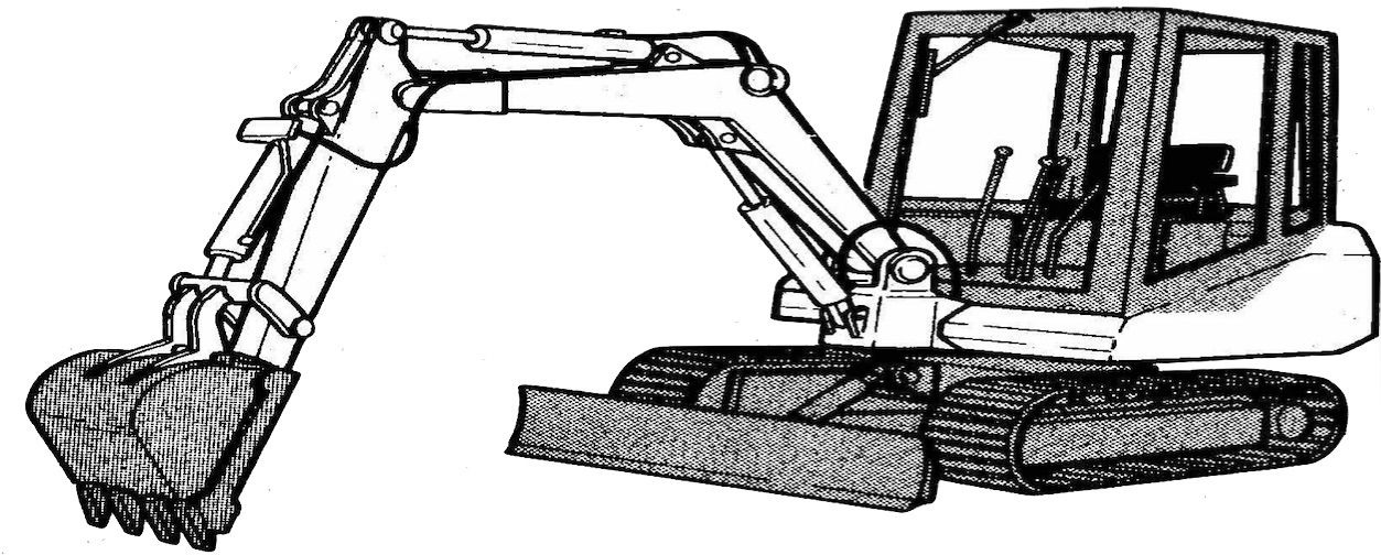
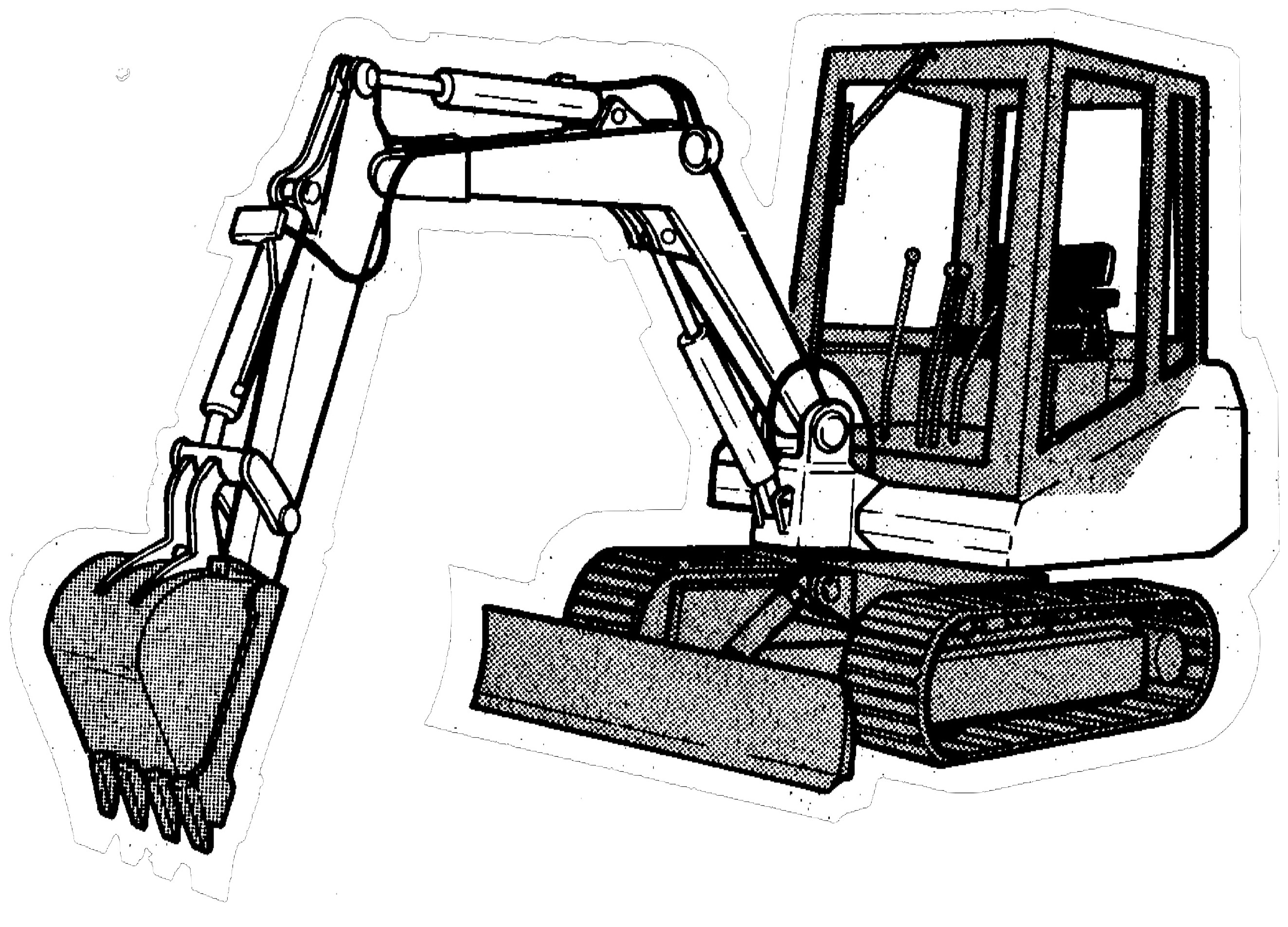
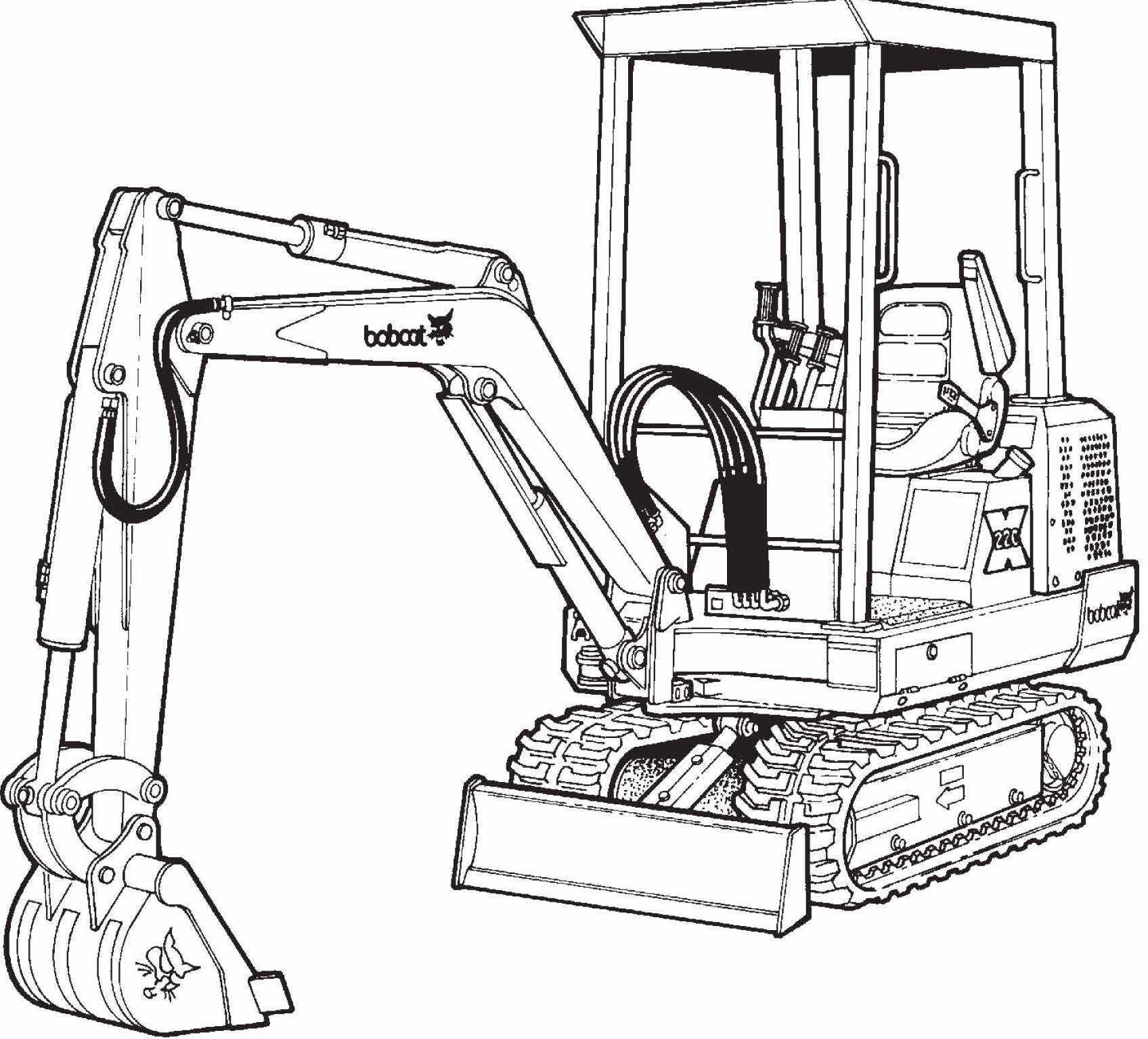
Pages from Service Manual (X220 Excavator) 6720503 (6-90)

MBOBC220OPEK.PDF
Price: $29.99 USD

Complete workshop & service manual with electrical wiring diagrams for Bobcat 220, X220 Excavator. It’s the same service manual used by dealers that guaranteed to be fully functional and intact without any missing page.

This Bobcat 220, X220 Excavator service & repair manual (including maintenance, overhaul, disassembling & assembling, adjustment, tune-up, operation, inspecting, diagnostic & troubleshooting…) is divided into different sections. Each section covers a specific component or system with detailed illustrations. A table of contents is placed at the beginning of each section. Pages are easily found by category, and each page is expandable for great detail. The printer-ready PDF documents work like a charm on all kinds of devices.

FILELIST:
Operation & Maintenance Manual (220 Excavator) 6720124 (11-89).pdf
Operation & Maintenance Manual (220 Excavator) 6720379 (11-89).pdf
Operation & Maintenance Manual (220 Excavator) 6720448 (4-92).pdf
Operation & Maintenance Manual (X220 Excavator) 6722250 (10-98).pdf
Service Manual (220 Excavator) 6722345 (9-92).pdf
Service Manual (X220 Excavator) 6720230 (5-89).pdf
Service Manual (X220 Excavator) 6720503 (6-90).pdf

EXCERPT:
“SWING MOTOR (Cont’d)”
“Assembly (Cont’d)”
“Clamp the shaft and bearing housing so the output shaft is down.”
“Pour a small amount of clean hydraulic fluid into the shaft and bearing housing for start–up lubrication.”
“Install the shaft face seal and wear plate as shown [A]. Install the drive, Geroler and valve drive.”
“Motor Timing”
“The direction that the output shaft rotates is determined by timing. Time the motor as follows:”
“Locate the largest open pocket in the Geroler (Item 1) [B]. Install the valve plate (Item 2) [B] and locate the open slot that is over the largest open Geroler pocket.”
“Align one of the side openings in the valve with the valve plate slot that is over the largest open Geroler pocket.”
“Engage the valve with the valve drive (Item 3) [B] by rotating it clockwise until the spline teeth mesh (1/2 tooth).”
“Install the inner and outer face seals on the balance ring as shown [C].”
“Install the springs, pins and balance ring in the valve housing. Hold the balance ring in place, through the forward port in the valve housing, while installing the valve housing over the valve.”
“Install and tighten the four bolts in a crisscross pattern. Tighten the bolts to 450 in.–lbs. (50 Nm) torque. Tighten the case drain plug to 50 in.–lbs. (5,5 Nm) torque.”

Posted on

Bobcat 130 Hydraulic Excavator Factory Service & Shop Manual

Service Manual (130 Hydraulic Excavator) 6570485 (4-87)

MBOBC130OPEK.PDF
Price: $29.99 USD

Complete workshop & service manual with electrical wiring diagrams for Bobcat 130 Hydraulic Excavator. It’s the same service manual used by dealers that guaranteed to be fully functional and intact without any missing page.

This Bobcat 130 Hydraulic Excavator service & repair manual (including maintenance, overhaul, disassembling & assembling, adjustment, tune-up, operation, inspecting, diagnostic & troubleshooting…) is divided into different sections. Each section covers a specific component or system with detailed illustrations. A table of contents is placed at the beginning of each section. Pages are easily found by category, and each page is expandable for great detail. The printer-ready PDF documents work like a charm on all kinds of devices.

EXCERPT:
CONTENTS
10 ENGINE
11 STRUCTURE AND FUNCTION
12 TESTING AND ADJUSTING
13 DISASSEMBLY AND ASSEMBLY1
20 POWER TRAIN
21 STRUCTURE AND FUNCTION
23 DISASSEMBLY AND ASSEMBLY
24 MAINTENANCE STANDARD
30 UNDERCARRIAGE
31 STRUCTURE AND FUNCTION
33 DISASSEMBLY AND ASSEMBLY
34 MAINTENANCE STANDARD
60 HYDRAULIC SYSTEM
61 STRUCTURE AND FUNCTION
62 TESTING AND ADJUSTING
63 DISASSEMBLY AND ASSEMBLY
64 MAINTENANCE STANDARD
70 WORK EQUIPMENT
7 3 DISASS.EMBL Y AND ASSEMBLY
80 ELECTRICAL SYSTEM
81 STRUCTURE AND FUNCTION
NOTE: This machine has a 24 volt electrical system.

SWING PRIORITY VALVE
OPERATION
Swing at neutral
• When the swing is at neutral, no pilot pressure oil flows from the solenoid valve. The swing priority valve is not actuated, so the pressurized oil from the front main pump passes through port P1 and flows to the arm-Lo control valve.
When operating swing
When the swing is operated, the limit switch on the linkage is actuated. This actuates the solenoid valve, and pilot pressure acts on port PB4 of the swing priority valve, and pushes the spool to the left.
When this happens, the pressurized oil flowing from the front main pump to the arm low control valve is restricted by the swing priority valve. The arm speed is controlled,· so simultaneous operations are made easier.

Posted on

Bobcat 116 Hydraulic Excavator Factory Service & Shop Manual

Service Manual (116 Hydraulic Excavator) 6570484 (4-87)

MBOBC116OPEK.PDF
Price: $29.99 USD

Complete workshop & service manual with electrical wiring diagrams for Bobcat 116 Hydraulic Excavator. It’s the same service manual used by dealers that guaranteed to be fully functional and intact without any missing page.

This Bobcat 116 Hydraulic Excavator service & repair manual (including maintenance, overhaul, disassembling & assembling, adjustment, tune-up, operation, inspecting, diagnostic & troubleshooting…) is divided into different sections. Each section covers a specific component or system with detailed illustrations. A table of contents is placed at the beginning of each section. Pages are easily found by category, and each page is expandable for great detail. The printer-ready PDF documents work like a charm on all kinds of devices.

Operator’s Manual (116 Hydraulic Excavator) 6570362 (4-88).pdf
Operator’s Manual (116 Hydraulic Excavator) 6570790 (4-88).pdf
Service Manual (116 Hydraulic Excavator) 6570484 (4-87).pdf

EXCERPT:
CONTENTS
10 ENGINE
12 TESTING AND ADJUSTING
1 3 DISASSEMBLY AND ASSEMBLY
20 POWER TRAIN
21 STRUCTURE AND FUNCTION
23 DISASSEMBLY AND ASSEMBLY
24 MAINTENANCE STANDARD
30 UNDERCARRIAGE
31 STRCTURE AND FUNCTION
33 DISASSEMBLY AND ASSEMBLY
34 MAINTENANCE STANDARD
60 HYDRAULIC SYSTEM
61 STRUCTURE AND FUNCTION
62 TESTING AND ADJUSTING
63 DISASSEMBLY AND ASSEMBLY
64 MAINTENANCE STANDARD
70 WORK EQUIPMENT
71 STRUCTURE AND FUNCTION
73 DISASSEMBLY AND ASSEMBLY
7 4 MAINTENANCE STANDARD
80 ELECTRICAL SYSTEM
81 STRUCTURE AND FUNCTION

TESTING TRAVEL OF CONTROL VALVE SPOOL
Put a steel tape in contact with control valve spool (1) to be tested and measure the distance the spool moves when the lever is operated.
* When measuring with one worker, pull the control lever with a string, or disconnect the rod at the spool end and move the spool directly to measure.
[Reference]
When results of test show that spool stroke is not within standard value:
Remove cover (2) of the spool and check if bolt (3) is loose. If there is no abnormality, disassemble the control valve and test.

Posted on

BMW Z8 2000-2003 Workshop Repair & Service Manual

BMW Z8 2000-2003

MBMWZ4NPES.PDF
Price: $29.99 USD

Complete digital official shop manual contains service, maintenance, and troubleshooting information for the BMW Z8 2000-2003. Diagnostic and repair procedures are covered in great detail to repair, maintain, rebuild, refurbish or restore your vehicle like a professional mechanic in local service/repair workshop. This cost-effective quality manual is 100% complete and intact as should be without any missing pages. It is the same factory shop manual used by dealers that guaranteed to be fully functional to save your precious time.

This manual for BMW Z8 2000-2003 is divided into different sections. Each section covers a specific component or system and, in addition to the standard service procedures, includes disassembling, inspecting, and assembling instructions. A table of contents is placed at the beginning of each section. Pages are easily found by category, and each page is expandable for great detail. It is in the cross-platform PDF document format so that it works like a charm on all kinds of devices. You do not need to be skilled with a computer to use the manual.

EXCERPT:
2000-2003 ENGINE Engine Mechanical – Repair Instructions – Z8
CONNECTING ROD WITH BEARINGS
11 24 571 REPLACING ALL CONROD BEARINGS (S62)
(piston removed)
Install new conrod bearing shells.
Insert one blue (1) and one red (2) bearing shell for each conrod.
Fig. 413: Installing New Conrod Bearing Shells
Install pistons, refer to 11 25 530 REMOVING AND INSTALLING/REPLACING ALL PISTONS (S62) .
Check connecting-rod bearing clearance:
Fig. 414: Checking Conrod Bearing Clearance
Piston in BDC position.
Fit special tool 00 2 590 (Plastigage Type PG 1) to the oil-free crankshaft.
Place bearing caps in position, making sure that matching numbers are paired.
Use the old connecting-rod bolts to check connecting-rod clearance.
Tighten down conrod bolts with special tool 00 9 120.
Fig. 415: Tightening Conrod Bolts
Tightening Torque 11 24 1AZ, refer to 11 24 CONNECTING RODS AND BEARINGS .
Remove bearing cover and read off bearing clearance across width of pinched plastic thread with the help of the measuring scale.
Fig. 416: Checking Connecting-Rod Clearance
Conrod bearing clearance, refer to 11 21 CRANKSHAFT AND BEARINGS S62 .
 Remove plastic thread.
 Lubricate crankshaft and bearing shells.
 Insert new conrod bolts and tighten down.
Tightening Torque 11 24 1AZ, refer to 11 24 CONNECTING RODS AND BEARINGS .
PISTON WITH RINGS
11 25 530 REMOVING AND INSTALLING/REPLACING ALL PISTONS (S62)
Special tools required:
 00 1 450
 00 9 120
 11 3 480
 11 7 180
(engine removed)
Removal
Removal of pistons is described separately from installation. Assembly sequence for removal and installation is
different.
Mount engine on special tool 00 1 450 and remove both cylinder heads. Refer to 11 12 517 Removing and installing both cylinder heads (S62) .
Remove lower oil sump section.
Remove oil circuit changeover valve on left and right. Refer to 11 13 540 Removing and installing/replacing
left oil circuit changeover valve (S62) and 11 13 550 Removing and installing/replacing right oil circuit
changeover valve (S62) .
CAUTION: Reinstall piston, connecting rod and bearing shells back in the same position and in the same installation location.
Conrod and conrod bearing cover are designated with same pair number:
do not interchange / confuse.
In the E52 Series, the oil pump is removed with the upper oil sump section. The procedure is described in the work step Removing and installing upper oil sump section. Refer to 11 13 010 Removing and installing/replacing upper oil sump section (S62) .
In event of heavy oil carbon residue:
Carefully remove oil carbon residue from cylinder wall.

Posted on

BMW Z4 2002-2016 Workshop Repair & Service Manual

BMW Z4 2.8i-3.0i-3.5i-3.5is 2009-2016 Service Manual

MBMWZ4NPES.PDF
Price: $29.99 USD

Complete digital official shop manual contains service, maintenance, and troubleshooting information for the 2002-2016 BMW Z4 (E85/E86/E89) 2.8i/3.0i/3.5i/3.5is. Diagnostic and repair procedures are covered in great detail to repair, maintain, rebuild, refurbish or restore your vehicle like a professional mechanic in local service/repair workshop. This cost-effective quality manual is 100% complete and intact as should be without any missing pages. It is the same factory shop manual used by dealers that guaranteed to be fully functional to save your precious time.

This manual for 2002-2016 BMW Z4 (E85/E86/E89) 2.8i/3.0i/3.5i/3.5is is divided into different sections. Each section covers a specific component or system and, in addition to the standard service procedures, includes disassembling, inspecting, and assembling instructions. A table of contents is placed at the beginning of each section. Pages are easily found by category, and each page is expandable for great detail. It is in the cross-platform PDF document format so that it works like a charm on all kinds of devices. You do not need to be skilled with a computer to use the manual.

EXCERPT:
SUSPENSION Front Axle – Repair – Z4
3121 WHEEL BEARINGS AND STUB AXLE
31 21 180 REMOVING AND INSTALLING/REPLACING BEARING FOR FRONT WHEEL
Necessary preliminary tasks
 Remove BRAKE DISC
NOTE:  Check brake pads and replace if necessary!
Release screws (1).
Tightening torque 31 21 1AZ .
Press wheel bearing (2) off swivel bearing with a suitable tool.
Installation:
Replace screws.
When reusing, recut all the threads in the wheel bearing.
Keep contact surface (1) of swivel bearing and wheel bearing clean and free from oil and grease.

ENGINE
Engine – Repair Instructions – N51, N52, N52K 6-Cylinder
00 ENGINE, GENERAL
00 DANGER OF POISONING IF OIL IS INGESTED/ABSORBED THROUGH THE SKIN Danger of poisoning!
Ingesting oil or absorbing through the skin may cause poisoning!
Possible symptoms are:
 Headaches
 Dizziness
 Stomach aches
 Vomiting
 Diarrhoea
 Cramps/fits
 Unconsciousness
Protective measures/rules of conduct:
 Pour oil only into appropriately marked containers
 Do not pour oil into drinking vessels (drinks bottles, glasses, cups or mugs)
 Observe country-specific safety regulations
First aid measures:
 Do not induce vomiting.
If the person affected is still conscious, he/she must rinse out their mouth with water, drink plenty of water and consult a doctor immediately.
If the person affected is unconscious, do not administer anything by mouth, place the person in the recovery position and seek immediate medical attention.
00 RISK OF INJURY IF OIL COMES INTO CONTACT WITH EYES AND SKIN
Danger of injury!
NOTE: Removal and installation procedures apply to 3-Series; 5-Series is similar.