Posted on

Acura ZDX 2010-2013 Workshop Repair & Service Manual

Sample Acura-ZDX ENGINE Cylinder Head

MACRZDX1013NPES.PDF
Price: $19.99 USD

Complete digital official shop manual contains service, maintenance, and troubleshooting information for the Acura ZDX 2010-2013. Diagnostic and repair procedures are covered in great detail to repair, maintain, rebuild, refurbish or restore your vehicle like a professional mechanic in local service/repair workshop. This cost-effective quality manual is 100% complete and intact as should be without any missing pages. It is the same factory shop manual used by dealers that guaranteed to be fully functional to save your precious time.

This manual for Acura ZDX 2010-2013 is divided into different sections. Each section covers a specific component or system and, in addition to the standard service procedures, includes disassembling, inspecting, and assembling instructions. A table of contents is placed at the beginning of each section. Pages are easily found by category, and each page is expandable for great detail. It is in the cross-platform PDF document format so that it works like a charm on all kinds of devices. You do not need to be skilled with a computer to use the manual.

FILELIST:
ACCESSORIES & EQUIPMENT AcuraLInk.pdf
ACCESSORIES & EQUIPMENT Adaptive Cruise Control (ACC).pdf
ACCESSORIES & EQUIPMENT Audio System.pdf
ACCESSORIES & EQUIPMENT Audio, Navigation and Telematics (Special Tools).pdf
ACCESSORIES & EQUIPMENT Automatic Dimming Inside Mirror.pdf
ACCESSORIES & EQUIPMENT Blind Spot Information System (BSI).pdf
ACCESSORIES & EQUIPMENT Body (Special Tools).pdf
ACCESSORIES & EQUIPMENT Body-Panoramic Glass Roof.pdf
ACCESSORIES & EQUIPMENT Bumpers.pdf
ACCESSORIES & EQUIPMENT Consoles.pdf
ACCESSORIES & EQUIPMENT Cruise Control.pdf
ACCESSORIES & EQUIPMENT Dashboard.pdf
ACCESSORIES & EQUIPMENT Dashlights Brightness Controller.pdf
ACCESSORIES & EQUIPMENT Doors.pdf
ACCESSORIES & EQUIPMENT Driver Position Memory System (DPMS).pdf
ACCESSORIES & EQUIPMENT Entry Lights Control System.pdf
ACCESSORIES & EQUIPMENT Exterior Lights.pdf
ACCESSORIES & EQUIPMENT Exterior Trim.pdf
ACCESSORIES & EQUIPMENT Fenderwell.pdf
ACCESSORIES & EQUIPMENT Frame.pdf
ACCESSORIES & EQUIPMENT Fuel Fill Door.pdf
ACCESSORIES & EQUIPMENT Gauges.pdf
ACCESSORIES & EQUIPMENT Glass.pdf
ACCESSORIES & EQUIPMENT HandsFreeLink System.pdf
ACCESSORIES & EQUIPMENT HomeLink Remote Control System.pdf
ACCESSORIES & EQUIPMENT Hood.pdf
ACCESSORIES & EQUIPMENT Horns.pdf
ACCESSORIES & EQUIPMENT Ignition Switch.pdf
ACCESSORIES & EQUIPMENT Immobilizer System.pdf
ACCESSORIES & EQUIPMENT Interior Lights.pdf
ACCESSORIES & EQUIPMENT Interior Trim.pdf
ACCESSORIES & EQUIPMENT Keyless Access System.pdf
ACCESSORIES & EQUIPMENT KeylessPower Door LocksSecurity System.pdf
ACCESSORIES & EQUIPMENT Mirrors.pdf
ACCESSORIES & EQUIPMENT Multiplex Integrated Control System.pdf
ACCESSORIES & EQUIPMENT Navigation System.pdf
ACCESSORIES & EQUIPMENT Panoramic Glass Roof.pdf
ACCESSORIES & EQUIPMENT Power Lumbar Support.pdf
ACCESSORIES & EQUIPMENT Power Mirrors.pdf
ACCESSORIES & EQUIPMENT Power Seats.pdf
ACCESSORIES & EQUIPMENT Power Tailgate.pdf
ACCESSORIES & EQUIPMENT Power Windows.pdf
ACCESSORIES & EQUIPMENT Rear Window Defogger.pdf
ACCESSORIES & EQUIPMENT Rearview Mirror With Rearview Camera Display.pdf
ACCESSORIES & EQUIPMENT Reminder Systems.pdf
ACCESSORIES & EQUIPMENT Safety Indicator System.pdf
ACCESSORIES & EQUIPMENT Seat Heaters.pdf
ACCESSORIES & EQUIPMENT Seats.pdf
ACCESSORIES & EQUIPMENT Tailgate.pdf
ACCESSORIES & EQUIPMENT Turn SignalHazard Warning Lights.pdf
ACCESSORIES & EQUIPMENT Ventilated Seats.pdf
ACCESSORIES & EQUIPMENT Wiper System Washer System.pdf
BRAKES Collision Mitigation Braking System (CMBS).pdf
BRAKES Conventional Brake System.pdf
BRAKES VSA System Components.pdf
CABIN AIR FILTER.pdf
DRIVELINEAXLES DrivelineAxle.pdf
DRIVELINEAXLES Rear Differential.pdf
ELECTRICAL Accessory Power Sockets.pdf
ELECTRICAL Battery Management System.pdf
ELECTRICAL Battery.pdf
ELECTRICAL Body Electrical (Special Tools.pdf
ELECTRICAL Charging System.pdf
ELECTRICAL Connectors and Harnesses.pdf
ELECTRICAL Engine Electrical (Special Tools).pdf
ELECTRICAL FuseRelay Boxes.pdf
ELECTRICAL Ground Distribution.pdf
ELECTRICAL OEM Wiring Diagram General Information.pdf
ELECTRICAL Power Distribution (Fuse ID).pdf
ELECTRICAL Relay and Control Unit Locations.pdf
ELECTRICAL Relays.pdf
ELECTRICAL Under-Dash FuseRelay Box.pdf
ELECTRICAL Under-Hood FuseRelay Box.pdf
ENGINE Cooling System.pdf
ENGINE Cylinder Head.pdf
ENGINE Engine Assembly.pdf
ENGINE Engine Block.pdf
ENGINE Engine Lubrication.pdf
ENGINE Engine Mount Control System.pdf
ENGINE Fan Controls.pdf
ENGINE Ignition System.pdf
ENGINE Intake Manifold and Exhaust System.pdf
ENGINE PERFORMANCE Advanced Diagnostics.pdf
ENGINE PERFORMANCE Catalytic Converter System-.pdf
ENGINE PERFORMANCE Catalytic Converter System.pdf
ENGINE PERFORMANCE Communication Systems (F-CAN, K-LINE).pdf
ENGINE PERFORMANCE EGR System.pdf
ENGINE PERFORMANCE Electronic Throttle Control System.pdf
ENGINE PERFORMANCE EVAP System.pdf
ENGINE PERFORMANCE Fuel and Emissions Systems.pdf
ENGINE PERFORMANCE Fuel Supply System.pdf
ENGINE PERFORMANCE Idle Control System.pdf
ENGINE PERFORMANCE IMT System.pdf
ENGINE PERFORMANCE Mode 6.pdf
ENGINE PERFORMANCE PCV System.pdf
ENGINE PERFORMANCE PGM-FI System.pdf
ENGINE PERFORMANCE VTEC.pdf
ENGINE Starting System—.pdf
ENGINE Starting System.pdf
FIRING ORDER & CYLINDER IDENTIFICATION Firing Order & Cylinder Identification.pdf
GENERAL INFO Battery Cable Reset.pdf
GENERAL INFORMATION General Information.pdf
GENERAL INFORMATION Specifications.pdf
GENERAL INFORMATION Symptom Check List Worksheets.pdf
GENERAL INFORMATION Trouble Shooting – Basic Procedures.pdf
HVAC Climate Control.pdf
HVAC HVAC (Special Tools).pdf
MAINTENANCE Maintenance.pdf
REMINDER INDICATOR RESET PROCEDURES.pdf
RESTRAINTS Restraints (Special Tools).pdf
RESTRAINTS Seat Belts.pdf
RESTRAINTS SRS (Supplemental Restraint System).pdf
STEERING Electronic Power Steering (EPS) System.pdf
STEERING Hydraulic Power Steering Components.pdf
STEERING Power Steering System.pdf
SUSPENSION Active Damper System.pdf
SUSPENSION ACURA WHEEL ALIGNMENT SPECIFICATIONS.pdf
SUSPENSION Front and Rear Suspension (Inspection).pdf
SUSPENSION Front Suspension.pdf
SUSPENSION Rear Suspension.pdf
SUSPENSION TPMS (Tire Pressure Monitoring System).pdf
SYSTEM WIRING DIAGRAMS 1.pdf
SYSTEM WIRING DIAGRAMS 2.pdf
TIRE PRESSURE MONITOR SYSTEMS.pdf
TRANSMISSION Automatic Transmission.pdf

EXCERPT:
Acura ZDX – 2012 ENGINE Engine Block – ZDX

CRANKSHAFT MAIN BEARING REPLACEMENT
MAIN BEARING CLEARANCE INSPECTION
1. Remove the main bearing caps and the bearing halves (see CRANKSHAFT AND PISTON REMOVAL ).
2. Clean each main journal and bearing half with a clean shop towel.
3. Place one strip of plastigage across each main journal.
4. Reinstall the bearings and the main bearing caps, then torque the bearing cap bolts to 74 N.m (7.5 kgf.m, 55 lbf.ft), and the bearing cap side bolts to 49 N.m (5.0 kgf.m, 36 lbf.ft) in the proper sequence (see step 22 ).
5. Remove the main bearing cap and the bearing half, and measure the widest part of the plastigage. Main Bearing-to-Journal Oil Clearance Standard (New): 0.019-0.045 mm (0.00075-0.00177 in)
Service Limit: 0.050 mm (0.00197 in)
Fig. 7: Checking Main Bearing-To-Journal Oil Clearance
6. If the plastigage measures too wide or too narrow, remove the crankshaft, and remove the upper half of the bearing. Install a new, complete bearing with the same color code, and recheck the clearance. Do not file, shim, or scrape the bearings or the caps to adjust clearance.
7. If the plastigage shows the clearance is still incorrect, try the next larger or smaller bearing (the color listed above or below that one), and check the clearance again. If the proper clearance cannot be obtained by using the appropriate larger or smaller bearings, replace the crankshaft and start over (see CRANKSHAFT AND PISTON REMOVAL ).

MAIN BEARING SELECTION
Block Bore Code Locations
Letters or bars have been stamped on the end of the engine block as a code for the size of each of the four main journal bores.
Use them, and the numbers or bars stamped on the crankshaft (codes for main journal size), to choose the correct bearings. If the codes are indecipherable because of an accumulation of dirt and dust, do not scrub them with a wire brush or scraper. Clean them only with solvent or detergent.
Fig. 8: Identifying Block Bore Code Locations
Fig. 9: Bearing Color Code Chart
Main Journal Code Locations (Numbers or Bars)
Fig. 10: Identifying Main Journal Code Locations (Numbers And Bars)

CONNECTING ROD BEARING REPLACEMENT
CONNECTING ROD BEARING CLEARANCE INSPECTION
1. Remove the connecting rod cap and the bearing half (see CRANKSHAFT AND PISTON
REMOVAL ).
2. Clean the connecting rod journal and the bearing half with a clean shop towel.
3. Place a strip of plastigage across the connecting rod journal.
4. Reinstall the bearing half and the connecting rod cap, and torque the connecting rod bolt to 20 N.m (2.0 kgf.m, 15 lbf.ft) + 90°.

Posted on

Acura SLX 1996-1999 Workshop Repair & Service Manual

Acura SLX 1996-1999 Preview

MACRSLX9699NPES.PDF
Price: $19.99 USD

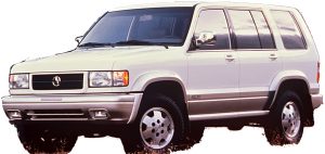
Complete digital official shop manual contains service, maintenance, and troubleshooting information for the Acura SLX 1996-1999. Diagnostic and repair procedures are covered in great detail to repair, maintain, rebuild, refurbish or restore your vehicle like a professional mechanic in local service/repair workshop. This cost-effective quality manual is 100% complete and intact as should be without any missing pages. It is the same factory shop manual used by dealers that guaranteed to be fully functional to save your precious time.

This manual for Acura SLX 1996-1999 is divided into different sections. Each section covers a specific component or system and, in addition to the standard service procedures, includes disassembling, inspecting, and assembling instructions. A table of contents is placed at the beginning of each section. Pages are easily found by category, and each page is expandable for great detail. It is in the cross-platform PDF document format so that it works like a charm on all kinds of devices. You do not need to be skilled with a computer to use the manual.

MAKE: Acura 1996-1999
— — — — — — — — —
MODEL: SLX
— — — — — — — — —
YEAR: 1996, 1997, 1998, 1999

EXCERPT:
1999-2001 ENGINES 3.2L & 3.5L V6
EXHAUST MANIFOLD
Removal & Installation
Disconnect negative battery cable. On right manifold, remove torsion bar. On left manifold, disconnect O2 sensor connector. On both manifolds, remove front exhaust pipe. On right manifold, remove EGR pipe bolts and gasket from exhaust manifold. On both manifolds, remove exhaust manifold heat shield. Remove exhaust manifolds from engine. To install, reverse removal procedure. Tighten bolts and nuts to specification. See TORQUE SPECIFICATIONS.
CYLINDER HEAD COVERS
Removal & Installation (3.2L – Left Side)
1. Disconnect negative battery cable. Remove air cleaner and duct assembly. Disconnect PCV hose.
Disconnect camshaft angle sensor connector.
2. Remove ground cable bolt from cylinder head cover. Remove ignition coils. Remove fuel injector harness bracket bolt. Remove 8 cylinder head cover bolts and cylinder head cover.
3. To install, apply RTV sealant to corners of end camshaft bearing towers. To complete installation, reverse removal procedure. Tighten bolts to specification. See TORQUE SPECIFICATIONS.
Removal & Installation (3.2L – Right Side)
1. Disconnect negative battery cable. Disconnect ventilation hose from cylinder head cover. Remove ignition coils. Remove heater pipe bolts from bracket. Disconnect fuel injector harness connector, then remove fuel injector harness bracket bolt.
2. Remove EGR pipe flare nut from EGR valve. Remove EGR pipe bracket bolt from rear of cylinder head.
Remove 2 EGR pipe bolts and nut from exhaust manifold. Remove EGR pipe. Remove 8 cylinder head cover bolts and cylinder head cover.
3. To install, apply RTV sealant to corners of end camshaft bearing towers. To complete installation, reverse removal procedure. Tighten bolts to specification. See TORQUE SPECIFICATIONS.
Removal (1999 3.5L – Left Side)
1. Disconnect battery ground cable. Drain engine coolant from radiator. Remove engine cover from dowels on common chamber. Remove air cleaner duct assembly and air cleaner element.
NOTE: Disconnect Mass Airflow (MAF) sensor connector, Intake Air Temperature
(IAT) sensor connector, and PCV hose before air cleaner duct assembly is removed.
2. Disconnect following wiring connectors and bonding cable:
 Manifold Absolute Pressure (MAP) sensor.
 Vacuum Switching Valve (VSV) for Induction Air Control Valve (IACV) actuator.
 Ignition coils for left bank.
 Fuel injectors for left bank.
 Idle air control (IAC) valve.
 Throttle position sensor (TPS).
 Bonding cable.
 Others as necessitated.
3. Disconnect following vacuum hoses:
 Brake master VAC
 Canister
 VSV for IACV actuator
 Duty solenoid valve
 PCV
4. Disconnect radiator upper and lower hoses. Remove engine harness from cylinder head cover. Remove upper fan guide. Remove cooling fan and clutch assembly. Remove drive belt by rotating auto tensioner
clockwise.
5. Remove power steering oil pump pulley. Remove fan pulley and bracket assembly. Remove idle pulley assembly. Remove auto tensioner assembly. Remove crankshaft pulley using Crankshaft Holder (J-8614-
01).
6. Remove timing belt covers from right bank side and left bank side in that order. Remove ignition coil assemblies for the left side bank. Remove cylinder head cover assembly.
Removal (1999 3.5L – Right Side)
1. Disconnect battery cables, and remove battery. Drain engine coolant from radiator. Remove engine cover from dowels on common chamber. Remove air cleaner duct assembly and air cleaner element.
2. Disconnect following wiring connectors and ground cable:
 EGR valve.
 Fuel injectors for right bank.
 Ignition coils for right bank.
 Ground cable.
 Others as necessitated.

Posted on

Acura RDX 2007-2012 Workshop Repair & Service Manual

Acura RDX 2007-2012 Repair Manual – SAMPLE

MACRRDX0712OPEK.PDF.zip
Price: $19.99 USD

Complete digital official shop manual contains service, maintenance, and troubleshooting information for the Acura RDX 2007-2012. Diagnostic and repair procedures are covered in great detail to repair, maintain, rebuild, refurbish or restore your vehicle like a professional mechanic in local service/repair workshop. This cost-effective quality manual is 100% complete and intact as should be without any missing pages. It is the same factory shop manual used by dealers that guaranteed to be fully functional to save your precious time.

This manual for Acura RDX 2007-2012 is divided into different sections. Each section covers a specific component or system and, in addition to the standard service procedures, includes disassembling, inspecting, and assembling instructions. A table of contents is placed at the beginning of each section. Pages are easily found by category, and each page is expandable for great detail. It is in the cross-platform PDF document format so that it works like a charm on all kinds of devices. You do not need to be skilled with a computer to use the manual.

Buy the best manual on the Internet from responsible merchant and get instant download without surprise.

INSTANT Delivery: A download link will be sent to you instantly after payment. Simply click on the link and save it to your computer. You can use this Manual as long as you wish with no restrictions.

PRINTABLE with Diagrams: Just print the manual out and start to work. You can also use the manual with your laptop in your garage.

Customer SATISFACTION: If there is any problem, just drop a quick email. Within hours the issue shall be taken care of.

REFUND Policy: We sell high quality products only. In case there is any problem with your purchase, a replacement link will be sent to you. If we are at fault, you get 100% refund.

EXCERPT:

DTC B1001: MICU INTERNAL (CPU) ERROR; DTC B1002: MICU INTERNAL (EEPROM) ERROR
NOTE: If you are troubleshooting multiple DTCs, be sure to follow the instructions in BCAN System Diagnosis Test Mode A (see TROUBLESHOOTING – B-CAN SYSTEM DIAGNOSIS TEST MODE A).
1. Clear the DTCs with the HDS.
2. Turn the ignition switch OFF, and then back ON (II).
3. Wait for 6 seconds or more.
4. Check for DTCs with the HDS.
Is DTC B1001 and/or B1002 indicated?
YES – Faulty MICU, replace the under-dash fuse/ relay box.
NO – Intermittent failure, the system is OK at this time.

Posted on

Acura NSX 1991-2005 Workshop Repair & Service Manual

Preview Acura NSX 1991-2005 Workshop Repair & Service Manual

MACRNSX9105OPES.PDF.zip
Price: $19.99 USD

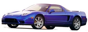
Complete digital official shop manual contains service, maintenance, and troubleshooting information for the Acura/Honda NSX 1991-2005. Diagnostic and repair procedures are covered in great detail to repair, maintain, rebuild, refurbish or restore your vehicle like a professional mechanic in local service/repair workshop. This cost-effective quality manual is 100% complete and intact as should be without any missing pages. It is the same factory shop manual used by dealers that guaranteed to be fully functional to save your precious time.

This manual for Acura/Honda NSX 1991-2005 is divided into different sections. Each section covers a specific component or system and, in addition to the standard service procedures, includes disassembling, inspecting, and assembling instructions. A table of contents is placed at the beginning of each section. Pages are easily found by category, and each page is expandable for great detail. It is in the cross-platform PDF document format so that it works like a charm on all kinds of devices. You do not need to be skilled with a computer to use the manual.

EXCERPT:
General Information
Special Tools
Specifications
Maintenance
Engine
Cooling
Fuel and Emissions
Transaxle
Steering
Suspension
Brakes
Body
Heater and Air Conditioner
Electrical (Including SRS)

Outline – Description
This engine is a 2,977 cc DOHC mid-ship unit having 6 cylinders of 90° -V configuration; it is water cooled and equipped with a center plug type pent roof combustion chamber. It is specified for unleaded fuel and uses a PGM-FI (Multipoint injection) system. This engine incorporates a new mechanism called Honda Variable Valve Timing and Lift Electronic
Control System (VTEC). This mechanism, the world’s first, allows the timing and lift of the intake and exhaust valves to be changed simultaneously. The engine also includes a new electronically controlled intake manifold system that can change the volume of the intake chamber.

This engine has the following new features.
VTEC; High output and a broad power band is achieved through control of low-speed and high-speed valve operation by the PGM-FI ECU. (Two knock sensors are used to detect octane level of the fuel.)
Titanium connecting rods; Accommodate high rotation speed and high output. Titanium material of light weight and high strength is used for the connecting rods. (Strength is at the same level as iron.) (Weight is about 30% lighter than iron.)
New mechanism to the intake system; Increased low and middle speed torque and higher output can both be achieved by switching the chamber volume of the intake manifold according to engine speed. This is electronically controlled.
Cooling system for the mid-ship engine:
– Radiator located in front compartment (An aluminum alloy radiator and pipes made of aluminum alloy)
– Engine room cooling fan
– Expansion tank

The cylinder block is highly rigid with deep water jackets.

In order to achieve lighter weight, magnesium is used for the following parts:
– Cylinder head cover
– Intake manifold cover
– Intake manifold chamber

Posted on

Acura Legend 1986-1995 Workshop Repair & Service Manual

Acura Legend 1986-1995 Workshop Repair & Service Manual

Preview ’95 Coupe Supplement

MACRLGN8695OPES.PDF.zip
Price: $19.99 USD

Complete digital official shop manual contains service, maintenance, and troubleshooting information for the Acura Legend 1986-1995. Diagnostic and repair procedures are covered in great detail to repair, maintain, rebuild, refurbish or restore your vehicle like a professional mechanic in local service/repair workshop. This cost-effective quality manual is 100% complete and intact as should be without any missing pages. It is the same factory shop manual used by dealers that guaranteed to be fully functional to save your precious time.

This manual for Acura Legend 1986-1995 is divided into different sections. Each section covers a specific component or system and, in addition to the standard service procedures, includes disassembling, inspecting, and assembling instructions. A table of contents is placed at the beginning of each section. Pages are easily found by category, and each page is expandable for great detail. It is in the cross-platform PDF document format so that it works like a charm on all kinds of devices. You do not need to be skilled with a computer to use the manual.

FILELIST:
’88-’90 Coupe
’91 Coupe Supplement.pdf
’91 Sedan.pdf
’92 Coupe Supplement.pdf
’92 Sedan Supplement.pdf
’93 Coupe Supplement.pdf
’93 Sedan Supplement.pdf
’94 Coupe Supplement.pdf
’94 Sedan Supplement.pdf
’95 Coupe Supplement.pdf
’95 Sedan Supplement.pdf

EXCERPT:
Control Unit Input Test (KN model).
Disconnect the 8-P connector from the control unit.
Inspect the connector and socket terminals to be sure they are all making good contact.
• If the terminals are bent, loose or corroded, repair them as necessary, and recheck the system.
• If the terminals look OK, make the following input tests at the connector.
• If any test indicates a problem, find and correct the cause, then recheck the system.
• If all the input tests prove OK, the control unit must be faulty; replace it.
NOTE:
If the shift lock solenoid clicks when you step on the brake pedal with the ignition switch ON (II) (with the shift lever in 0 ), the shift lock system is electronically OK. If the shift lever cannot be shifted from 0, test the shift lever position switch as described on page 23-168 in the 1991 Legend Shop Manual, 62SPOOO, and see section 14 of the same Shop Manual.

Interlock System
Component location Index (KN Model)
CAUTION:
• All SRS wiring harnesses are covered with yellow outer insulation.
•Before disconnecting any part of the SRS wire harness, install the short connectors (see page 23-54 of 1993 Legend Shop Manual Supplement 62SP021).
• Replace the entire affected SRS harness assembly if it has an open circuit or damaged wiring.

General Information
Special Tools
Specifications
Maintenance
Engine:
Engine Tune-up
Timing Belt
Cylinder Heads
Engine Removal/Installation
Intake Manifold/Exhaust
Cooling
Engine Block
Engine Lubrication
Fuel and Emissions:
PGM-FI System
Control Systems
Transaxle:
Clutch
Manual Transmission
Automatic Transmission
Driveshafts
Power Steering
Suspension
Brakes
Body
Heater and Air Conditioning:
Heater
Air Conditioning
Electrical
Radiator Cap Testing
Coolant Level Inspection
Engine Oil Level Inspection
Engine Oil Replacement
Air Cleaner Inspection/ Replacement
Compression Pressure Inspection
Spark Plug Inspection
Alternator Belt Adjustment
P/S Pump Belt Adjustment
A/C Compressor Belt Adjustment
Idle Speed Inspection/ Adjustment
Tailpipe Emissions Inspection
Ignition Timing Inspection and Setting
Special Tools
Index
Troubleshooting:
General
Noise and Vibration
Fluid Leaks
Maintenance:
Pump Belt Adjustment
Fluid Replacement
On-Car Checks:
Rack Guide Adjustment
Pump Pressure Check
Steering Wheel Rotation Play
Assist Check
Speed Sensor Replacement
Column
Steering Wheel
Steering Lock
Pump:
Index / Inspection
Replacement
Preload Inspection
Pulley Replacement
Control Valve Inspection and Replacement
Housing Disassembly
Housing Reassembly
Gearbox:
Index / Inspection
Valve Body Unit Disassembly
Valve Body Unit Assembly
Removal
Overhaul
Installation
Ball Joint Boot Installation