Complete workshop & service manual with electrical wiring diagrams for JCB Side Engine Loadalls (526-56, 531-70, 531-T70, 533-105, 535-95, 535-T95, 536-60, 536-T60, 536-70, 536-T70, 541-70, 541-T70, 550-80, 550-T80). It’s the same service manual used by dealers that guaranteed to be fully functional and intact without any missing page.
This JCB Side Engine Loadalls (526-56, 531-70, 531-T70, 533-105, 535-95, 535-T95, 536-60, 536-T60, 536-70, 536-T70, 541-70, 541-T70, 550-80, 550-T80) service & repair manual (including maintenance, overhaul, disassembling & assembling, adjustment, tune-up, operation, inspecting, diagnostic & troubleshooting…) is divided into different sections. Each section covers a specific component or system with detailed illustrations. A table of contents is placed at the beginning of each section. Pages are easily found by category, and each page is expandable for great detail. The printer-ready PDF documents work like a charm on all kinds of devices.
FILELIST:
9813-0900 – JCB Side Engine Loadalls (526-56, 531-70, 531-T70, 533-105, 535-95, 535-T95, 536-60, 536-T60, 536-70, 536-T70, 541-70, 541-T70, 550-80, 550-T80) Service Manual.pdf
9813-1500 – JCB Side Engine Loadalls (526-56, 531-70, 531-T70, 533-105, 535-95, 535-T95, 536-60, 536-T60, 536-70, 536-T70, 541-70, 541-T70, 550-80, 550-T80) Service Manual.pdf
EXCERPT:
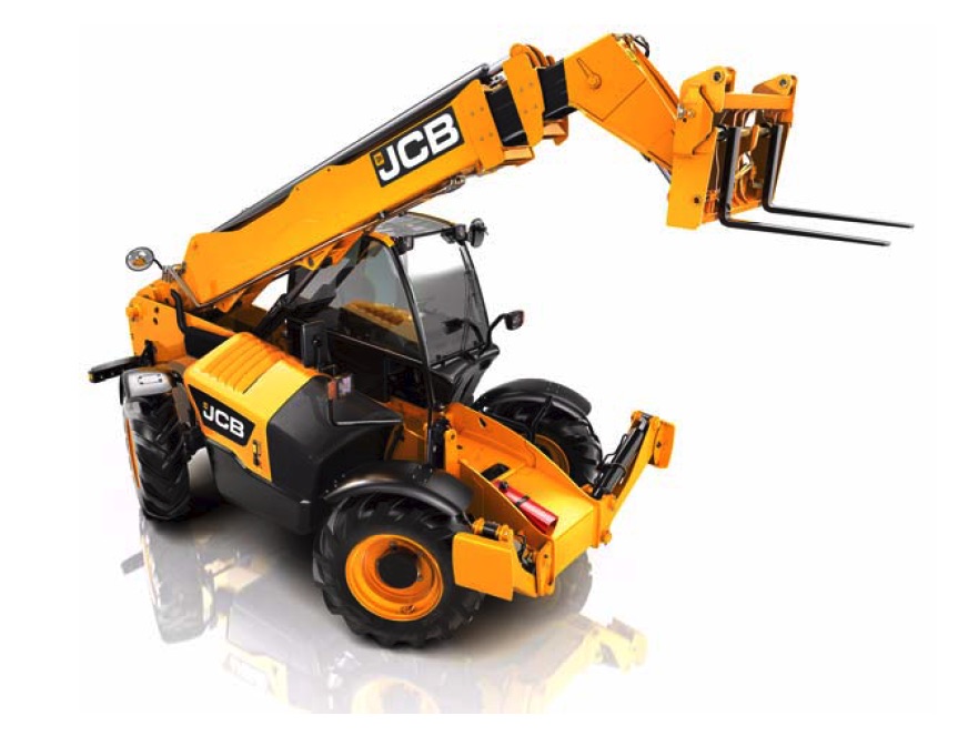
Service Manual
Side Engine Loadalls
Section 1 – General Information
Section 2 – Care and Safety
Section 3 – Routine Maintenance
Section B – Body and Framework
Section C – Electrics
Section E – Hydraulics
Section F – Transmission
Section G – Brakes
Section H – Steering
Section K – Engine
Section M – Electrical and Electronic Data Systems
…
Brake Piston Seal Leakage
The most common reason for internal piston seal leakage is a build-up of axle contamination as a result of excessive brake wear caused by extended service periods.
Two types of internal leakage can occur within the axle or hub:
– Low Pressure Leaks – Seal damage, or scoring to seal component surfaces, caused by a build-up of metal particles.
– High Pressure Leaks – Mechanical leakage past a
badly damaged or perished seal.
Note: The low pressure leak test should be performed first. Low pressure leaks are difficult to find using a high pressure test – seals and other components can distort and form a seal under pressure.
The following procedures explain how to check for low or high pressure leaks without the need to dismantle the axle first. The test must only be done when the axle is COLD.
Front Axles
…