Posted on

JCB Rough Terrain Fork Lift 926/930/940 Factory Service & Shop Manual


Pages from 9803-5100 – JCB Rough Terrain Fork Lift (926, 930, 940) Service Manual

MJCBRTFLOPEK.zip
Price: $29.99 USD

Complete workshop & service manual with electrical wiring diagrams for JCB Rough Terrain Fork Lift (926, 930, 940). It’s the same service manual used by dealers that guaranteed to be fully functional and intact without any missing page.

This JCB Rough Terrain Fork Lift (926, 930, 940) service & repair manual (including maintenance, overhaul, disassembling & assembling, adjustment, tune-up, operation, inspecting, diagnostic & troubleshooting…) is divided into different sections. Each section covers a specific component or system with detailed illustrations. A table of contents is placed at the beginning of each section. Pages are easily found by category, and each page is expandable for great detail. The printer-ready PDF documents work like a charm on all kinds of devices.

9803-5100 – JCB Rough Terrain Fork Lift (926, 930, 940) Service Manual.pdf

EXCERPT:
Service Manual
Rough Terrain Fork Lift
Section 1 – General Information
Section 2 – Care and Safety
Section 3 – Maintenance
Section A – Attachments
Section B – Body and Framework
Section C – Electrics
Section E – Hydraulics
Section F – Transmission
Section G – Brakes
Section H – Steering
Section K – Engine

Removal and Replacement
Removal
1 Before commencing, set machine in straight ahead position on firm level ground. Apply parking brake and stop engine.
2 Remove carriage and forks. K Removal ( T B-15).
3 Disconnect and plug hydraulic hoses 39-A and breather pipe 39-B. View 39-X shows the arrangement for early models whilst view 39-Y shows later models; refer to the view applicable to your machine.
4 Attach a hoist to the top of the mast to prevent mast tipping when tilt rams are disconnected.
5 Support tilt rams. Remove bolts 39-C, washers 39-D and pivot pins 39-E and withdraw tilt rams.
6 Take weight of mast on the hoist. Remove bolts 39-F, pivot pins 39-G and lower mast to ground.
Replacement
The procedure for replacing the mast is a reversal of the removal procedure.

Posted on

JCB Manual Pack


Pages from 9803-1400 – JCB Attachments Service Manual

MJCBMISCOPMK.zip
Price: $29.99 USD

JCB Manual Pack

FILELIST:
9801-9907 – JCB VLT Lighting Tower Operator Manual.pdf
9803-1400 – JCB Attachments Service Manual.pdf
9803-9320 – JCB Dumpster TD7, TD10 Service Manual.pdf
9803-9430 – JCB ZT 20D Service Manual.pdf
9803-9570 – JCB Dumpster HTD5 Service Manual.pdf
9803-9985 – JCB CP1 & CP2 Digital Control Panels Service Manual.pdf
9806-2150 – JCB Industrial Engine Systems LPG 3.0 Engine Workshop Manual.pdf
9806-3080 – Lombardini indirect injection Diesel engines type 15LD225, 15LD315, 15LD350, 15LD400, 15LD440 Workshop Manual.pdf
9806-4005a – Lombardini Gearbox Workshop Manual.pdf
9806-4060 – Lombardini CHD series Engine Workshop Manual.pdf
9806-4061 – Lombardini LDW 1503, LDW 1603, LDW 2004, LDW 2004/T, LDW 2204, LDW 2204/T CHD Use & Maintenance Manual.pdf
9806-4650 – Installation, Service & Maintenance Manual for STAMFORD BC Range of Generators.pdf
9806-4750 – Himoinsa Generators Self-regulating Alternators Series Eco-ECP Operating & Maintenance Instructions.pdf
9806-4800 – JCB Digital Control Panel Operators Manual.pdf
9806-5000 – Sincro SK160 4 Poles Brushless Alternators Use and Maintenance Manual.pdf
9811-1870 – Generator Set – G50R, G80R, G55X, G55QX, G66X, G66QX, G88X, G88QX, G110X, G110QX, G120X, G120QX Operator Manual.pdf
9811-2800 – Generator Set – G17, G17Q, G20R, G22, G22Q, G30R, G33, G33Q Operator Manual.pdf
9811-2850 – Generator Set – G144, G144Q, G175, G175Q, G220, G220Q, G130R, G160R, G200R Operator Manual.pdf
9811-2900 – Generator Set – G330, G330Q, G350, G350Q, G380, G380Q, G400, G400Q, G400, G440Q, G550, G550Q Operator Manual.pdf
9811-4550 – Generator Set – Models G8X to G45QX Operator Manual.pdf
9811-4600 – Generator Set – Models G60RX to G115QX Operator Manual.pdf
9811-4650 – Generator Set – Models G130RX to G220QX Operator Manual.pdf
9811-4700 – Generator Set – Models G250RX to G600X Operator Manual.pdf
9811-5050 – Lighting Tower LT9 Operator Manual.pdf
9821-1950 – Lighting Tower LTM9 Operator Manual.pdf

EXCERPT:
Service Manual Dumpster TD7, TD10
General Information 1
Care & Safety 2
Routine Maintenance 3
Attachments A
Body & Framework B
Electrics C
Controls D
Hydraulics E
Gearboxes F
Track & Running Gear J
Engine L

Hydraulic Fluid Quality
Construction machinery uses a large volume of fluid in the hydraulic system for power transmission, equipment lubrication, rust prevention and sealing.
According to a survey conducted by a pump manufacturer, seventy per cent of the causes of problems in hydraulic equipment were attributable to inadequate maintenance of the quality of the hydraulic fluid.
Therefore, it is obvious that control of the quality of the hydraulic fluid helps prevent hydraulic equipment problems and greatly improves safety and reliability. Furthermore from an economic angle it extends the life of the hydraulic fluid if quality is maintained.
Effects of Contamination
Once inside the system, hydraulic circuit contaminants greatly effect the performance and life of hydraulic equipment. For example, contaminants in a hydraulic pump develop internal wear to cause internal leakage and hence lower discharges. Wear particles generated will circulate with the hydraulic fluid to cause further deterioration in the performance of this and other equipment.
Contaminants also enter principal sliding sections of the equipment causing temporary malfunction, scuffing, sticking and leakage and can lead to major problems.
The main contaminants can be classified as follows:-
1 Solid Particles – sand, fibres, metallic particles, welding scale, sealing materials and wear particles etc.

Posted on

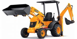
JCB Backhoe Loader Midi CX, Mini CX, Mini CX 4×4, Micro Factory Service & Shop Manual


Pages from 9803-9340 – JCB Backhoe Loader Mini CX, Mini CX 4×4, Micro Tier 3 Service Manual

MJCBMCXOPES.zip
Price: $29.99 USD

Complete workshop & service manual with electrical wiring diagrams for JCB Backhoe Loader Midi CX, Mini CX, Mini CX 4×4, Micro. It’s the same service manual used by dealers that guaranteed to be fully functional and intact without any missing page.

This JCB Backhoe Loader Midi CX, Mini CX, Mini CX 4×4, Micro service & repair manual (including maintenance, overhaul, disassembling & assembling, adjustment, tune-up, operation, inspecting, diagnostic & troubleshooting…) is divided into different sections. Each section covers a specific component or system with detailed illustrations. A table of contents is placed at the beginning of each section. Pages are easily found by category, and each page is expandable for great detail. The printer-ready PDF documents work like a charm on all kinds of devices.

FILELIST:
9803-9340 – JCB Backhoe Loader Mini CX, Mini CX 4×4, Micro Tier 3 Service Manual.pdf
9803-9400 – JCB Backhoe Loader Midi CX Service Manual.pdf

EXCERPT:
Service Manual
Midi CX Backhoe Loader
Section 1 – General Information
Section 2 – Care and Safety
Section 3 – Maintenance
Section A – Attachments
Section B – Body and Framework
Section C – Electrics
Section D – Controls
Section E – Hydraulics
Section F – Transmission
Section G – Brakes
Section H – Steering
Section K – Engine

Service Manual
Mini CX
Section 1 – General Information
Section 2 – Care & Safety
Section 3 – Routine Maintenance
Section A – Attachments
Section B – Body & Framework
Section C – Electrics
Section E – Hydraulics
Section F – Transmission
Section G – Brakes
Section H – Steering
Section K – Engine

High Pressure Relief Valve
Dismantling and Assembly
The components of the high pressure relief valve are shown at A. There is a second relief valve underneath the pump.
Use a suitable protection sleeve B when assembling backup ring C and ‘O’ ring D. Make sure the ‘O’ ring is fitted on the pressure side as shown.
After assembly the valve setting should be checked.
Low Pressure Relief Valve
Dismantling and Assembly
The components of the low pressure relief valve are shown at E.
Wrap tape around the threads of the valve cap when fitting the ‘O’ ring.
After assembly the valve setting should be checked.

Posted on

JCB Hydraulic Excavator JZ235, JZ255 – TIER III AUTO Factory Service & Shop Manual


Pages from 9803-6560 – JCB Hydraulic Excavator JZ235, JZ255 – TIER III AUTO Service Manual

MJCBJZ2X5OPES.zip
Price: $29.99 USD

Complete workshop & service manual with electrical wiring diagrams for JCB Hydraulic Excavator JZ235, JZ255 – TIER III AUTO. It’s the same service manual used by dealers that guaranteed to be fully functional and intact without any missing page.

This JCB Hydraulic Excavator JZ235, JZ255 – TIER III AUTO service & repair manual (including maintenance, overhaul, disassembling & assembling, adjustment, tune-up, operation, inspecting, diagnostic & troubleshooting…) is divided into different sections. Each section covers a specific component or system with detailed illustrations. A table of contents is placed at the beginning of each section. Pages are easily found by category, and each page is expandable for great detail. The printer-ready PDF documents work like a charm on all kinds of devices.

FILELIST:
9803-6560 – JCB Hydraulic Excavator JZ235, JZ255 – TIER III AUTO Service Manual.pdf

EXCERPT:
Service Manual
JZ235, JZ255 – TIER III AUTO
Section 1 – General Information
Section 2 – Care and Safety
Section 3 – Routine Maintenance
Section B – Body & Framework
Section C – Electrics
Section E – Hydraulics
Section F – Transmission
Section J – Track and Running Gear
Section K – Engine

Electrical System
Battery
Note: Before commencing work on the battery you must read the following procedure in Health and Safety; K Battery ( T 3-5).
Note: If a battery requires replacement then both batteries must be replaced.
Battery Isolator
To disconnect the batteries from the machine electrics a battery isolator has been fitted.
Important: DO NOT use the battery isolator when the engine is running, this may result in damage to the machine electrics.

Posted on

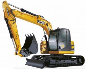
JCB Hydraulic Excavator JZ70/JZ140/JZ140 ZTS Factory Service & Shop Manual


Pages from 9803-9910 – JCB Hydraulic Excavator JZ140 Service Manual


INSTANT DOWNLOAD


Complete workshop & service manual with electrical wiring diagrams for JCB Hydraulic Excavator JZ70, JZ140, JZ140 ZTS. It’s the same service manual used by dealers that guaranteed to be fully functional and intact without any missing page.

This JCB Hydraulic Excavator JZ70/JZ140/JZ140 ZTS service & repair manual (including maintenance, overhaul, disassembling & assembling, adjustment, tune-up, operation, inspecting, diagnostic & troubleshooting…) is divided into different sections. Each section covers a specific component or system with detailed illustrations. A table of contents is placed at the beginning of each section. Pages are easily found by category, and each page is expandable for great detail. The printer-ready PDF documents work like a charm on all kinds of devices.

FILELIST:
9803-6030 – JCB Hydraulic Excavator JZ70 Service Manual.pdf
9803-6530 – JCB Hydraulic Excavator JZ140 ZTS Service Manual.pdf
9803-9910 – JCB Hydraulic Excavator JZ140 Service Manual.pdf

EXCERPT:
Service Manual
JZ140
Service Manual – JZ140
Section 1 – General Information
Section 2 – Care & Safety
Section 3 – Maintenance
Section B – Body & Framework
Section C – Electrics
Section E – Hydraulics
Section F – Transmission
Section J – Track & Running Gear
Section K – Engine

Changing the Inner Air Filter Element
Note: Do not attempt to wash or clean the elements – they must only be renewed.
Note: Do not run the engine with the dust valve F removed.
Note: Change the outer element more frequently if operating in dusty conditions. A new inner element must be fitted at least every other time the outer element is changed. As a reminder, mark the inner element with a pen each time the outer element is changed.
1 Stop the engine.
2 Press clips A and lift off cover B. Remove outer element C.
3 Lift up pulls J and remove inner element G.
4 Clean the inside of cover B and canister D.
5 Carefully insert the new inner element G into the canister. Make sure it seats correctly. Check seal H is fully seated.
6 Insert a new outer element C into the canister, check seal E is fully seated. Fit cover B with dust valve F at the bottom. Push the cover firmly into position and make sure it is secured by clips A.
7 Make sure that the wire is connected to the Air Filter Blocked switch.
8 Check all hoses for condition and tightness.


INSTANT DOWNLOAD