Posted on

JCB FASTRAC 2115, 2125, 2135, 2140, 2150, 2155, 2170, 3155, 3185 Factory Service & Shop Manual


Pages from 9803-8050 – JCB FASTRAC 2155, 2170 Service Manual

MJCB2115FT3185OPES.zip
Price: $29.99 USD

Complete workshop & service manual with electrical wiring diagrams for JCB FASTRAC 2115, 2125, 2135, 2140, 2150, 2155, 2170, 3155, 3185. It’s the same service manual used by dealers that guaranteed to be fully functional and intact without any missing page.

This JCB FASTRAC 2115, 2125, 2135, 2140, 2150, 2155, 2170, 3155, 3185 service & repair manual (including maintenance, overhaul, disassembling & assembling, adjustment, tune-up, operation, inspecting, diagnostic & troubleshooting…) is divided into different sections. Each section covers a specific component or system with detailed illustrations. A table of contents is placed at the beginning of each section. Pages are easily found by category, and each page is expandable for great detail. The printer-ready PDF documents work like a charm on all kinds of devices.

9803-8020 – JCB FASTRAC 2115, 2125, 2135, 2140, 2150, 3155, 3185 Service Manual.pdf
9803-8050 – JCB FASTRAC 2155, 2170 Service Manual.pdf

EXCERPT:
Service Manual
Fastrac 2155 and 2170
Section 1 – General Information
Section 2 – Care and Safety
Section 3 – Maintenance
Section A – Attachments
Section B – Body and Framework
Section C – Electrics
Section D – Controls
Section E – Hydraulics
Section F – Transmission
Section G – Brakes
Section H – Steering
Section S – Suspension
Section T – Engine

Footbrake Callipers
Removal and Replacement
Note: Illustrations show typical calliper mounting positions.
Removal
1 Park the machine on firm, level ground, apply the parking brake and remove the starter key.
!MWARNING
A raised and badly supported machine can fall on you.
Position the machine on a firm, level surface before raising one end. Ensure the other end is securely chocked. Do not rely solely on the machine hydraulics or jacks to support the machine when working under it.
Disconnect the battery, to prevent the engine being started while you are beneath the machine.
2 Chock the front wheels. Jack up the appropriate wheel, support the machine on an axle stand and remove the wheel.
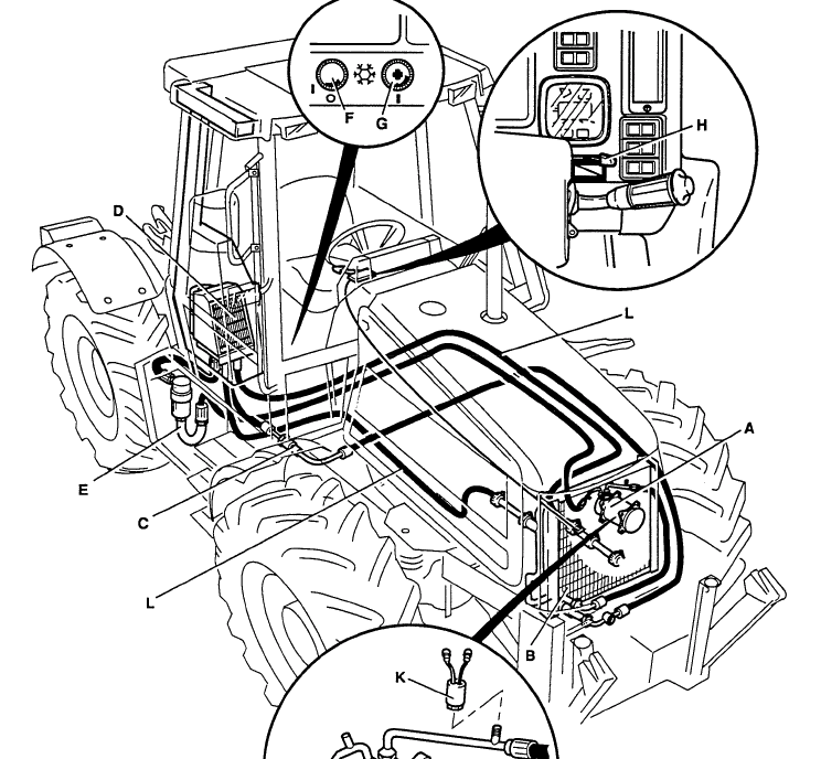
3 Disconnect the brake pipe A (front) or B (rear) and catch the fluid in a suitable container.
4 If the pistons are free, force the pads back until they clear the disc. If necessary remove the pads to provide clearance (see Section 3). Remove bolts C (front) or D (rear) and remove the calliper.

Posted on

JCB FASTRAC 1115, 1115S, 1125, 1135 Factory Service & Shop Manual


Pages from 9803-8010 – JCB FASTRAC 1115, 1115S, 1125, 1135 Service Manual

MJCB11X5OPES.zip
Price: $29.99 USD

Complete workshop & service manual with electrical wiring diagrams for JCB FASTRAC 1115, 1115S, 1125, 1135. It’s the same service manual used by dealers that guaranteed to be fully functional and intact without any missing page.

This JCB FASTRAC 1115, 1115S, 1125, 1135 service & repair manual (including maintenance, overhaul, disassembling & assembling, adjustment, tune-up, operation, inspecting, diagnostic & troubleshooting…) is divided into different sections. Each section covers a specific component or system with detailed illustrations. A table of contents is placed at the beginning of each section. Pages are easily found by category, and each page is expandable for great detail. The printer-ready PDF documents work like a charm on all kinds of devices.

9803-8010 – JCB FASTRAC 1115, 1115S, 1125, 1135 Service Manual.pdf

EXCERPT:
Hydraulics
54- 1 Electronic Draft Control
Fault finding
• Introduction
The Electronic Draft Control System is self-monitoring for faults. These are identified by error codes indicated by a diagnostic LED. Refer to Interpreting the Diagnostic LED under Fault Diagnosis.
Experience has shown that faults are unlikely to lie within the electronic components.
Understand how the system works before attempting rectification (see Introduction, System Activation Procedure and Operation to ensure that all controls are set to allow full linkage movement).
Note: If you are unable to diagnose a fault by following the fault finding procedure or by visual examination, contact JCB Landpower Service for further assistance.

Posted on

JCB Excavators 801, 802, 803, 804 Factory Service & Shop Manual


Pages from 9803-3145 – JCB 802.7 Plus, 802.7 Super, 803 Plus, 803 Super, 804 Plus, 804 Super Mini-Excavator Service Manual

MJCB801ME804OPES.zip
Price: $29.99 USD

Complete workshop & service manual with electrical wiring diagrams for JCB Excavators 801, 801.4, 801.5, 801.6, 802, 802.4, 802 Super, 802.7, 802.7 Plus, 802.7 Super, 803, 803 Plus, 803 Super, 804, 804 Plus, 804 Super. It’s the same service manual used by dealers that guaranteed to be fully functional and intact without any missing page.

This JCB Excavators 801, 801.4, 801.5, 801.6, 802, 802.4, 802 Super, 802.7, 802.7 Plus, 802.7 Super, 803, 803 Plus, 803 Super, 804, 804 Plus, 804 Super service & repair manual (including maintenance, overhaul, disassembling & assembling, adjustment, tune-up, operation, inspecting, diagnostic & troubleshooting…) is divided into different sections. Each section covers a specific component or system with detailed illustrations. A table of contents is placed at the beginning of each section. Pages are easily found by category, and each page is expandable for great detail. The printer-ready PDF documents work like a charm on all kinds of devices.

FILELIST:
9803-3110 – JCB Hydrapower 802.7, 803, 804 Mini-Excavator Service Manual.pdf
9803-3130 – JCB Hydrapower 801.4, 801.5, 801.6 Mini-Excavator Service Manual.pdf
9803-3140 – JCB 802, 802.4, 802 Super Mini-Excavator Service Manual.pdf
9803-3145 – JCB 802.7 Plus, 802.7 Super, 803 Plus, 803 Super, 804 Plus, 804 Super Mini-Excavator Service Manual.pdf
9803-3161 – JCB 801 Tracked-Excavator Service Manual.pdf

EXCERPT:
Typical – Dismantling and Assembly
WARNING
If air or hydraulic pressure is used to force out the piston assembly, ensure that the end cap is securely fitted. Severe injury can be caused by a suddenly released piston rod.
The numerical sequence shown in the figures are intended as a guide to dismantling.
Discard all seals and ‘O’ rings.
Try to lay out the parts in the correct order for assembly. For assembly the sequence should be reversed.
Fit new ‘O’ rings and seals on assembly.
Torque tighten the end cap and piston nut.
For correct torque settings, refer to Section 3.

Posted on

JCB Articulated Dump Truck 712, 714, 716, 718, 722 Factory Service & Shop Manual

Pages from 9803-7160 – JCB Articulated Dump Truck 714, 718 Service Manual


INSTANT DOWNLOAD


Complete workshop & service manual with electrical wiring diagrams for JCB Articulated Dump Truck 712, 714, 716, 718, 722. It’s the same service manual used by dealers that guaranteed to be fully functional and intact without any missing page.

This JCB Articulated Dump Truck 712, 714, 716, 718, 722 service & repair manual (including maintenance, overhaul, disassembling & assembling, adjustment, tune-up, operation, inspecting, diagnostic & troubleshooting…) is divided into different sections. Each section covers a specific component or system with detailed illustrations. A table of contents is placed at the beginning of each section. Pages are easily found by category, and each page is expandable for great detail. The printer-ready PDF documents work like a charm on all kinds of devices.

FILELIST:
9803-5000 – JCB Articulated Dump Truck 700- Series (712, 716) Service Manual.pdf
9803-7160 – JCB Articulated Dump Truck 714, 718 Service Manual.pdf
9803-7170 – JCB Articulated Dump Truck 722 Service Manual.pdf
9813-0550 – JCB Articulated Dump Truck 714, 718 Service Manual.pdf

EXCERPT:
Articulated Dump Truck – 722
Section 1 – General Information
Section 2 – Care and Safety
Section 3 – Routine Maintenance
Section B – Body and Framework
Section C – Electrics
Section E – Hydraulics
Section F – Transmission
Section G – Brakes
Section H – Hydraulic Steering
Section K – Engine
Section S – Suspension

Service
Manual
ARTICULATED
DUMP TRUCK
714 & 718
General Information
Care & Safety
Routine Maintenance
Optional Equipment
Body & Framework
Electrics
Hydraulics
Transmission
Brakes
Steering
Engine
Suspension…

Fitting the Inductive Transmitter
The distance between the contact face of the inductive transmitter and the tip of the teeth on the spur gear must be between 0.6 and 0.8 mm (0.023 and 0.032 inches). If necessary, the clearance can be adjusted by the use of a shim.
To calculate the thickness of the shim required, proceed as follows:
Measure from the tip of the spur gear teeth to the housing face (dimension 1).
Measure from the end face to the shoulder on the inductive transmitter (dimension 2).
For example:
If dimension 1 = 26.20 mm
And the required clearance = 0.70 mm
Then the inductive transmitter can only be allowed to screw in 26.2 – 0.7 = 25.5 mm
If dimension 2 = 26.5 mm
Then shim size = 26.5 – 25.5 = 1 mm
To fit the inductive transmitter, proceed as follows:
1 Assemble the shim (as calculated above) to the inductive transmitter.
2 Fit a new O-ring into the ring groove on the transmission housing.
3 Screw the inductive transmitter in to the housing.


INSTANT DOWNLOAD


Posted on

JCB Side Engine Loadalls (535-125 Hi Viz, 535-140 Hi Viz, 540-140, 540-170, 550-140, 550-170) Factory Service & Shop Manual


Pages from 9803-3750 – JCB Side Engine Loadalls (535-125 Hi Viz, 535-140 Hi Viz, 540-140, 540-170, 550-140, 550-170) Service Manual

MJCB535LOA550OPES.zip
Price: $29.99 USD

Complete workshop & service manual with electrical wiring diagrams for JCB Side Engine Loadalls (535-125 Hi Viz, 535-140 Hi Viz, 540-140, 540-170, 550-140, 550-170). It’s the same service manual used by dealers that guaranteed to be fully functional and intact without any missing page.

This JCB Side Engine Loadalls (535-125 Hi Viz, 535-140 Hi Viz, 540-140, 540-170, 550-140, 550-170) service & repair manual (including maintenance, overhaul, disassembling & assembling, adjustment, tune-up, operation, inspecting, diagnostic & troubleshooting…) is divided into different sections. Each section covers a specific component or system with detailed illustrations. A table of contents is placed at the beginning of each section. Pages are easily found by category, and each page is expandable for great detail. The printer-ready PDF documents work like a charm on all kinds of devices.

9803-3750 – JCB Side Engine Loadalls (535-125 Hi Viz, 535-140 Hi Viz, 540-140, 540-170, 550-140, 550-170) Service Manual.pdf

EXCERPT:
Service Manual
Side Engine Loadalls
Section 1 – General Information
Section 2 – Care and Safety
Section 3 – Routine Maintenance
Section B – Body and Framework
Section C – Electrics
Section E – Hydraulics
Section F – Transmission
Section G – Brakes
Section H – Steering
Section K – Engine
Section M – Electronic Data Systems

Solenoid Control Valve Cartridge – Single Fixing Type
Removal and Replacement
The gearbox control valve assembly features 7 (4 speed) or 8 (6 speed) solenoid control valve cartridges 7-A. The removal and replacement procedure is identical for all valve cartridges.
Removal
1 Clean off all debris, dirt and grit from around the solenoid control valves. There must be no ingress of debris, dirt or grit inside the valve block 7-H.
Important: Cleanliness is of the utmost importance when working on the gearbox. Any ingress of dirt or grit inside the valve block can cause serious damage to the control valves and gearbox.
2 Uncouple the electrical connector 7-B.
Note: If more than 1 valve cartridge is to be removed, label the electrical connectors to ensure correct assembly.
3 Note the phasing of the electrical connector block 7- G to ensure correct assembly.
4 Undo screw 7-C and remove clamp 7-D.
5 Pull the valve cartridge 7-A from the valve block. DO NOT grip the unit by its electrical connector block 7- G. The connector block is not designed as a leverage point.
Replacement