Complete workshop & service manual with electrical wiring diagrams for JCB Wheeled Loading Shovel 407B ZX, 408B ZX, 409B Z, 410B ZX, 411B ZX . It’s the same service manual used by dealers that guaranteed to be fully functional and intact without any missing page.
This JCB Wheeled Loading Shovel 407B ZX, 408B ZX, 409B Z, 410B ZX, 411B ZX service & repair manual (including maintenance, overhaul, disassembling & assembling, adjustment, tune-up, operation, inspecting, diagnostic & troubleshooting…) is divided into different sections. Each section covers a specific component or system with detailed illustrations. A table of contents is placed at the beginning of each section. Pages are easily found by category, and each page is expandable for great detail. The printer-ready PDF documents work like a charm on all kinds of devices.
9803-4210 – JCB Wheeled Loading Shovel 407B ZX, 408B ZX, 409B Z, 410B ZX, 411B ZX Service Manual.pdf
EXCERPT:
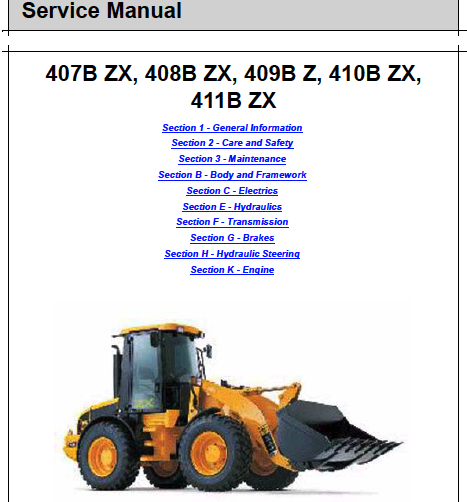
Service Manual
407B ZX, 408B ZX, 409B Z, 410B ZX,
411B ZX
Section 1 – General Information
Section 2 – Care and Safety
Section 3 – Maintenance
Section B – Body and Framework
Section C – Electrics
Section E – Hydraulics
Section F – Transmission
Section G – Brakes
Section H – Hydraulic Steering
Section K – Engine
…
Checking the Fluid Level (410B ZX, 411B ZX)
1 Apply the parking brake, put the transmission in neutral, lower the attachment to the ground. Make sure it is flat on the ground. Stop the engine.
2 Look at the fluid level in the plastic tube 14-A. The level should be above the red line on the tube. Later machines feature a sight glass as shown at 14-L. The level should be at, or above the red mark.
3 If necessary, top up with hydraulic fluid, through filler point 13-Z.
!MCAUTION
If the fluid is cloudy, then water or air has contaminated the system. This could damage the hydraulic pump. Contact your JCB Distributor immediately.
…