Posted on

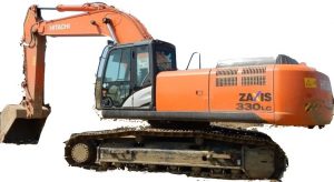
Hitachi ZAXIS 330, ZAXIS 330LC, ZAXIS 350H, ZAXIS 350LCH, ZAXIS 370MTH Factory Service & Shop Manual


Pages from W1HHE01 – Hitachi ZAXIS 330, 330LC, 350H, 350LCH, 370MTH Excavator Workshop Manual


INSTANT DOWNLOAD


Complete workshop & service manual with electrical wiring diagrams for Hitachi Excavator ZAXIS 330, ZAXIS 330LC, ZAXIS 350H, ZAXIS 350LCH, ZAXIS 370MTH. It’s the same service manual used by dealers that guaranteed to be fully functional and intact without any missing page.

This Hitachi Excavator ZX 330, ZX 330LC, ZX 350H, ZX 350LCH, ZX 370MTH service & repair manual (including maintenance, overhaul, disassembling & assembling, adjustment, tune-up, operation, inspecting, diagnostic & troubleshooting…) is divided into different sections. Each section covers a specific component or system with detailed illustrations. A table of contents is placed at the beginning of each section. Pages are easily found by category, and each page is expandable for great detail. The printer-ready PDF documents work like a charm on all kinds of devices.

FILELIST:
W1HHE01 – Hitachi ZAXIS 330, 330LC, 350H, 350LCH, 370MTH Excavator Workshop Manual.pdf
Hitachi ZAXIS 330, 330LC, 350H, 350LCH, 370MTH Hydraulic Excavator Technical Manual (Operational Principle).pdf
Hitachi ZAXIS 330, 330LC, 350H, 350LCH, 370MTH Hydraulic Excavator Technical Manual (Troubleshooting).pdf
Hitachi ZAXIS 330, 330LC, 350H, 350LCH, 370MTH Hydraulic Excavator Workshop Manual.pdf
CD.23_12_05 – Hitachi ZAXIS 250-3 Class, 280-3 Class, 350-3 Class Training Materials
PIHHE13 – Hitachi ZAXIS 330, 330LC, 350LC, 350LCN, 350H, 350LCH, 350K, 350LCK, 370, 370MTH Excavator Parts Catalog.pdf
PIHHE13 – Hitachi ZAXIS 330, 330LC, 350LC, 350LCN, 350H, 350LCH, 350K, 350LCK, 370, 370MTH Excavators Parts Catalog.pdf

EXCERPT:
SECTION 1 GENERAL INFORMATION
Group 1 Precautions for Disassembling and Assembling
Group 2 Tightening Torque
Group 3 Painting
SECTION 2 UPPERSTRUCTURE
Group 1 Cab
Group 2 Counterweight
Group 3 Main Frame
Group 4 Pump Device
Group 5 Control Valve
Group 6 Swing Device
Group 7 Pilot Valve
Group 8 Pilot Shut-Off Valve
Group 9 Shockless Valve
Group 10 Solenoid Valve
SECTION 3 UNDERCARRIAGE
Group 1 Swing Bearing
Group 2 Travel Device
Group 3 Center Joint
Group 4 Track Adjuster
Group 5 Front Idler
Group 6 Upper and Lower Roller
Group 7 Track
SECTION 4 FRONT ATTACHMENT
Group 1 Front Attachment
Group 2 Cylinder
SECTION 5 ENGINETECHNICAL MANUAL (Operational Principle)
SECTION 1 GENERAL
Group 1 Specifications
Group 2 Component Layout
Group 3 Component Specifications
SECTION 2 SYSTEM
Group 1 Control System
Group 2 Hydraulic System
Group 3 Electrical System
SECTION 3 COMPONENT OPERATION
Group 1 Pump Device
Group 2 Swing Device
Group 3 Control Valve
Group 4 Pilot Valve
Group 5 Travel Device
Group 6 Others (Upperstructure)
Group 7 Others (Undercarriage)
TECHNICAL MANUAL (Troubleshooting)
SECTION 4 OPERATIONAL PERFORMANCE TEST
Group 1 Introduction
Group 2 Engine Test
Group 3 Excavator Test
Group 4 Component Test
Group 5 Standard
SECTION 5 TROUBLESHOOTING
Group 1 General
Group 2 Component Layout
Group 3 Troubleshooting A
Group 4 Troubleshooting B
Group 5 Troubleshooting C
Group 6 Electrical System Inspection
Group 7 ICX

UNDERCARRIAGE / Track
Installation
1. Jack up the machine. Set the track under the lower roller so that the sprocket meshes with the track end.
Check the direction of track.
2. Hoist and place the track on sprocket (8).
3. With the machine jacked up, slowly operate the lever for the track to be installed in the forward direction. Turn travel device (9) and wind the track.
4. Wind the track until the connecting part of track link reaches front idler (4). Lower the machine.
Place a wooden block under shoe (5) and support shoe (5).


INSTANT DOWNLOAD


Posted on

Hitachi ZAXIS 330-3, 330LC-3, 350H-3, 350LCH-3, 350LCK-3, 350LC-3, 350LCN-3 Excavator Factory Service & Shop Manual


Pages from W1V7E00 – Hitachi ZAXIS 330-3, 330LC-3, 350H-3, 350LCH-3, 350LCK-3, 350LC-3, 350LCN-3 Hydraulic Excavator Workshop Manual

MHITZX330ZX350OPES.zip
Price: $29.99 USD

Hitachi ZAXIS 330-3, 330LC-3, 350H-3, 350LCH-3, 350LCK-3, 350LC-3, 350LCN-3 Excavator Factory Service & Shop Manual
Complete workshop & service manual with electrical wiring diagrams for Hitachi ZAXIS 330-3, 330LC-3, 350H-3, 350LCH-3, 350LCK-3, 350LC-3, 350LCN-3 Hydraulic Excavator. It’s the same service manual used by dealers that guaranteed to be fully functional and intact without any missing page.

This Hitachi ZAXIS 330-3, 330LC-3, 350H-3, 350LCH-3, 350LCK-3, 350LC-3, 350LCN-3 Hydraulic Excavator service & repair manual (including maintenance, overhaul, disassembling & assembling, adjustment, tune-up, operation, inspecting, diagnostic & troubleshooting…) is divided into different sections. Each section covers a specific component or system with detailed illustrations. A table of contents is placed at the beginning of each section. Pages are easily found by category, and each page is expandable for great detail. The printer-ready PDF documents work like a charm on all kinds of devices.

FILELIST:
TO1V7E00 – Hitachi ZAXIS 330-3, 330LC-3, 350H-3, 350LCH-3, 350LCK-3, 350LC-3, 350LCN-3 Hydraulic Excavator Technical Manual (Operational Principle).pdf
TT1V7E00 – Hitachi ZAXIS 330-3, 330LC-3, 350H-3, 350LCH-3, 350LCK-3, 350LC-3, 350LCN-3 Hydraulic Excavator Technical Manual (Troubleshooting).pdf
W1V7E00 – Hitachi ZAXIS 330-3, 330LC-3, 350H-3, 350LCH-3, 350LCK-3, 350LC-3, 350LCN-3 Hydraulic Excavator Workshop Manual.pdf
TT1V7E00 (attach to) – Electrical Wiring Diagrams
EM1V9HL11 – Hitachi ZAXIS 350LCK-3 Super Long Demolition Front Attachment Operator’s Manual.pdf
ENMDC1NA31 – Hitachi ZAXIS 130-6N, 160LC-6N, 180LC-6N, 210-6N, 210LC-6N, 250LC-6N, 300LC-6N, 350LC-6N, 380LC-6N Excavator Operator’s Manual.pdf
ENMDC1NASL11 – Hitachi ZAXIS 210LC-5N, 210LC-6N, 250LC-5N, 250LC-6N, 290LC-5N, 300LC-6N, 350LC-5N, 350LC-6N Hydraulic Excavator Operator’s Manual.pdf
P1V711 – Hitachi ZAXIS 330-3, 330LC-3, 350LC-3, 350LCN-3, 350H-3, 350LCH-3, 350K-3, 350LCK-3 Hydraulic Excavator Parts Catalog.pdf
P1V712 – Hitachi ZAXIS 330-3, 330LC-3, 350LC-3, 350LCN-3, 350H-3, 350LCH-3, 350K-3, 350LCK-3 Hydraulic Excavator Parts Catalog.pdf

EXCERPT:
SECTION 1 GENERAL INFORMATION
Group 1 Precautions for disassembling and Assembling
Group 2 Tightening Torque
Group 3 Painting
Group 4 Bleeding Air from Hydraulic Oil Tank
SECTION 2 UPPERSTRUCTURE
Group 1 Cab
Group 2 Counterweight
Group 3 Main Frame
Group 4 Pump Device
Group 5 Control Valve
Group 6 Swing Device
Group 7 Pilot Valve
Group 8 Pilot Shut-Off Solenoid Valve
Group 9 Signal Control Valve
Group 10 4-Spool Solenoid Valve Unit
Group 11 Engine
SECTION 3 UNDERCARRIAGE
Group 1 Swing Bearing
Group 2 Travel Device
Group 3 Center Joint
Group 4 Track Adjuster
Group 5 Front Idler
Group 6 Upper and Lower Roller
Group 7 Track
SECTION 4 FRONT ATTACHMENT
Group 1 Front Attachment
Group 2 Cylinder

UPPERSTRUCTURE / Pilot Valve
Remove Travel Pilot Valve
1. Remove bolts (3) (6 used) and washers (4) (6 used). Remove cover (2) from the lower of main frame (1).: 17 mm
2. Remove hoses (5) (4 used) and pipes (2) (2 used) from pilot valve (6). Attach identification tags to the removed hoses for reassembling. Cap the open end. : 17 mm, 19 mm
3. Remove floor mat (7).

Posted on

Hitachi ZX330 Excavator Factory Service & Shop Manual


Pages from WDDEEN00 – Hitachi ZX330-5G, ZX330LC-5G, ZX330H-5G, ZX330LCH-5G, ZX330K-5G, ZX330LCK-5G Hydraulic Excavator Workshop Manual

MHITZX330OPES.zip
Price: $29.99 USD

Hitachi ZX330 Excavator Factory Service & Shop Manual
Complete workshop & service manual with electrical wiring diagrams for Hitachi ZX330, ZX330-5G, ZX330LC-5G, ZX330H-5G, ZX330LCH-5G, ZX330K-5G, ZX330LCK-5G Excavator. It’s the same service manual used by dealers that guaranteed to be fully functional and intact without any missing page.

This service & repair manual (including maintenance, overhaul, disassembling & assembling, adjustment, tune-up, operation, inspecting, diagnostic & troubleshooting…) is divided into different sections. Each section covers a specific component or system with detailed illustrations. A table of contents is placed at the beginning of each section. Pages are easily found by category, and each page is expandable for great detail. The printer-ready PDF documents work like a charm on all kinds of devices.

FILELIST:
TO1V7E00 – Hitachi ZAXIS 330-3 class Hydraulic Excavator Technical Manual (Operational Principle).pdf
TT1V7E00 – Hitachi ZAXIS 330-3 class Hydraulic Excavator Technical Manual (Troubleshooting).pdf
TTLA0678TX – Hitachi ZAXIS 200-3 class, 240-3 class, 270-3 class, 330-3 class Training Text (Maintenance).pdf
WDDEEN00 – Hitachi ZX330-5G, ZX330LC-5G, ZX330H-5G, ZX330LCH-5G, ZX330K-5G, ZX330LCK-5G Hydraulic Excavator Workshop Manual.pdf
EM1V7SL21 – Hitachi ZAXIS 330LC-3, 350LC-3 (Super Long Front Rype H22) Operator’s Manual.pdf
TT1V7E00 (attach) – Hitachi ZAXIS 330-3 Class Hydraulic Circuit Diagram circuit_updated+infomation_1pages.pdf

EXCERPT:
SECTION 1 GENERAL INFORMATION
Group 1 Precautions for Disassembling and Assembling
Group 2 Tightening
Group 3 Painting
Group 4 Bleeding Air
Group 5 Pressure Release Procedure
Group 6 Preparation
SECTION 2 MAINTENANCE STANDARD
Group 1 Upperstructure
Group 2 Undercarriage
Group 3 Front Attachment
SECTION 3 UPPERSTRUCTURE
Group 1 Cab
Group 2 Counterweight
Group 3 Main Frame
Group 4 Engine
Group 6 Hydraulic Oil Tank
Group 7 Fuel Tank
Group 8 Pump Device
Group 9 Control Valve
Group 10 Swing Device
Group 11 Pilot Valve
Group 12 Solenoid Valve
Group 13 Signal Control Valve
SECTION 4 UNDERCARRIAGE
Group 1 Swing Bearing
Group 2 Travel Device
Group 3 Center Joint
Group 4 Track Adjuster
Group 5 Upper and Lower Rollers
Group 6 Track
SECTION 5 FRONT ATTACHMENT
Group 1 Front Attachment
Group 2 Cylinder

SECTION 3 UPPERSTRUCTURE
Disassembly of Pilot Shut-Off Solenoid Valve
IMPORTANT: Filter (9) cannot be removed.
1. Put the matching marks on body (4) and solenoid (2). Secure body (4) in a vise. Remove socket bolts (1) (2 used) from body (4). Remove solenoid (2) and O-ring (3) from body (4). : 4 mm
2. Remove plug (8) from body (4). Remove O-ring (7) from plug (8). : 6 mm
3. Remove spring (6) and spool (5) from body (4).

Posted on

Hitachi ZX 200/210/225/230/240/250/270/280 Excavator Factory Service & Shop Manual


Pages from W1V1E01 – Hitachi ZAXIS 200-3 class, 225US-3 class, 225USR-3 class, 240-3 class, 270-3 class Hydraulic Excavator Workshop Manual


INSTANT DOWNLOAD


Complete workshop & service manual with electrical wiring diagrams for Hitachi ZAXIS 200, ZAXIS 200LC, ZAXIS 210, ZAXIS 210H, ZAXIS 210K, ZAXIS 210LC, ZAXIS 210LCH, ZAXIS 210LCK, ZAXIS 210LCN, ZAXIS 210N, ZAXIS 225US, ZAXIS 225USLC, ZAXIS 225USR, ZAXIS 225USRLC, ZAXIS 225USRK, ZAXIS 225USRLCK, ZAXIS 230, ZAXIS 230LC, ZAXIS 240, ZAXIS 240H, ZAXIS 240LC, ZAXIS 240LCH, ZAXIS 240N, ZAXIS 250, ZAXIS 250H, ZAXIS 250K, ZAXIS 250LC, ZAXIS 250LCH, ZAXIS 250LCK, ZAXIS 250LCN, ZAXIS 270, ZAXIS 270LC, ZAXIS 280LC, ZAXIS 280LCN Excavator. It’s the same service manual used by dealers that guaranteed to be fully functional and intact without any missing page.

This Hitachi ZAXIS 200, 200LC, 210, 210H, 210K, 210LC, 210LCH, 210LCK, 210LCN, 210N, 225US, 225USLC, 225USR, 225USRLC, 225USRK, 225USRLCK, 230, 230LC, 240, 240H, 240LC, 240LCH, 240N, 250, 250H, 250K, 250LC, 250LCH, 250LCK, 250LCN, 270, 270LC, 280LC, 280LCN Excavator service & repair manual (including maintenance, overhaul, disassembling & assembling, adjustment, tune-up, operation, inspecting, diagnostic & troubleshooting…) is divided into different sections. Each section covers a specific component or system with detailed illustrations. A table of contents is placed at the beginning of each section. Pages are easily found by category, and each page is expandable for great detail. The printer-ready PDF documents work like a charm on all kinds of devices.

FILELIST:
TO1V1E01 – Hitachi ZAXIS 200-3 class, 225US-3 class, 225USR-3 class, 240-3 class, 270-3 class Hydraulic Excavator Technical Manual (Operationel Principle).pdf
TO178E02 – Hitachi ZAXIS 200 class, 225US class, 225USR class, 240 class, 270 class Hydraulic Excavator Technical Manual (Operationel Principle).pdf
TT1V1E00 – Hitachi ZAXIS 200-3 class, 240-3 class, 270-3 class Hydraulic Excavator Technical Manual (Troubleshooting).pdf
TT1V1E00 (attach to) – Hitachi ZAXIS 200-3, 240-3, 270-3 Class Hydraulic Circuit Diagram (Standard Piping).pdf
TT1V1E00 (attach to) – Hitachi ZAXIS 200-3, 240-3, 270-3, 330-3 Class Electrical Diagram.pdf
TT1V1E01 – Hitachi ZAXIS 200-3 class, 225US-3 class, 225USR-3 class, 240-3 class, 270-3 class Hydraulic Excavator Technical Manual (Troubleshooting).pdf
TT1V1E01 (attach to) – Hitachi ZAXIS 200-3 class, 225US-3 class, 225USR-3 class, 240-3 class, 270-3 class Hydraulic Excavator Electrical Wiring Digram.pdf
TT1V7E00 (attach to) – Hitachi ZAXIS 200-3 class, 225US-3 class, 225USR-3 class, 240-3 class, 270-3 class, 330-3 class Hydraulic Excavator Electrical Wiring Digram.pdf
TT178E02 – Hitachi ZAXIS 200-3 class, 225-3 class, 230-3 class, 270-3 class Hydraulic Excavator Technical Manual (Troubleshooting).pdf
TTLA0675ZX – Hitachi ZAXIS 200-3 class, 240-3 class, 270-3 class Training Text (Performance Check Troubleshooting).pdf
TTLA0676ZX – Hitachi ZAXIS 200-3 class, 240-3 class, 270-3 class Training Text (Performance Check Troubleshooting).pdf
TTLA0678ZX – Hitachi ZAXIS 200-3 class, 240-3 class, 270-3 class, 330-3 class Training Text (Maintenance).pdf
TTLA0687ZX – Hitachi ZAXIS 200-3 class, 240-3 class, 270-3 class Training Text (General Information).pdf
W1V1E01 – Hitachi ZAXIS 200-3 class, 225US-3 class, 225USR-3 class, 240-3 class, 270-3 class Hydraulic Excavator Workshop Manual.pdf
W178E01 – Hitachi ZAXIS 200, 225USR, 225US, 230-270 Hydraulic Excavator Workshop Manual.pdf
EM1U111 – Hitachi ZAXIS 200-3 class, 240-3 class, 270-3 class Hydraulic Excavator Operator’s Manual.pdf
EM1U421 – Hitachi ZAXIS 135US-3, 135USK-3, 135USL-3, 225US-3, 225USLC-3, 225USR-3, 225USRLC-3, 225USRK-3, 225USRLCK-3 Operator’s Manual.pdf
EM1V4SL11 – Hitachi ZAXIS 270LC-3, 280LC-3 (Super Long Front Type H18) Excavator Operator’s Manual.pdf
PIG6E15 – Hitachi ZAXIS 200, 200LC, 200-E, 200LC-E, 210, 210LC, 210H, 210LCH, 210K, 210LCK, 210N, 240 Excavator Parts Catalog.pdf
PIG617 – Hitachi ZAXIS 200, 200LC, 200-E, 200LC-E, 210, 210LC, 210H, 210LCH, 210K, 210LCK, 210N, 240 Excavator Parts Catalog.pdf
PIHDE14 – Hitachi ZAXIS 230, 230LC, 240H, 240LCH, 240K, 240LCK, 250, 250LC, 250LCN Excavator Parts Catalog.pdf
PIHDE14 – Hitachi ZAXIS 230, 230LC, 240H, 240LCH, 240K, 240LCK, 250, 250LC, 250LCN Excavators Parts Catalog.pdf
PIHG13 – Hitachi ZAXIS 270, 270LC, 280LC, 280LCN Excavators Parts Catalog.pdf
PIHGE13 – Hitachi ZAXIS 270, 270LC, 280LC, 280LCN Excavator Parts Catalog.pdf


INSTANT DOWNLOAD


EXCERPT:
SECTION 1 GENERAL INFORMATION
Group 1 Precautions for disassembling and Assembling
Group 2 Tightening Torque
Group 3 Painting
SECTION 2 UPPERSTRUCTURE
Group 1 Cab
Group 2 Counterweight
Group 3 Main Frame
Group 4 Pump Device
Group 5 Control Valve
Group 6 Swing Device
Group 7 Pilot Valve
Group 8 Pilot Shut-Off Valve
Group 9 Signal Control Valve
Group 10 Solenoid Valve
SECTION 3 UNDERCARRIAGE
Group 1 Swing Bearing
Group 2 Travel Device
Group 3 Center Joint
Group 4 Track Adjuster
Group 5 Front Idler
Group 6 Upper and Lower Roller
Group 7 Track
SECTION 4 FRONT ATTACHMENT
Group 1 Front Attachment
Group 2 Cylinder
SECTION 5 ENGINE

TECHNICAL MANUAL (Operational Principle)
SECTION 1 GENERAL
Group 1 Specification
Group 2 Component Layout
Group 3 Component Specification
SECTION 2 SYSTEM
Group 1 Control System
Group 2 Hydraulic System
Group 3 Electrical System
SECTION 3 COMPONENT OPERATION
Group 1 Pump Device
Group 2 Swing Device
Group 3 Control Valve
Group 4 Pilot Valve
Group 5 Travel Device
Group 6 Signal Control Valve
Group 7 Others (Upperstructure)
Group 8 Others (Undercarriage)
TECHNICAL MANUAL (Troubleshooting)
SECTION 4 OPERATIONAL PERFORMANCE
TEST
Group 1 Introduction
Group 2 Engine Test
Group 3 Excavator Test
Group 4 Component Test
Group 5 Standard
SECTION 5 TROUBLESHOOTING
Group 1 General
Group 2 Component Layout
Group 3 Troubleshooting A
Group 4 Troubleshooting B
Group 5 Troubleshooting C
Group 6 Electrical System Inspection
Group 7 ICX

UNDERCARRIAGE / Swing Bearing
REMOVE AND INSTALL SWING BEARING
Before removing and installing the swing bearing, the upperstructure must be removed first. For removal and installation of the upperstructure, refer to “Remove and Install Main Frame” section (W2-3-1).
In this section, the procedure starts on the premise that the upperstructure has already been removed.
Removal
1. Put the matching marks on inner race (1) of swing bearing (4) and track frame (2).
2. Remove bolts (3) (36 used) from inner race (1) of swing bearing (4).
ZX200-3 class, 225US-3 class, 225USR-3 class : 30 mm
ZX240-3 class, 270-3 class : 32 mm
CAUTION: Swing bearing (4) weight:
ZX200-3 class, 225US-3 class, 225USR-3 class: 226 kg (500 Ib)
ZX240-3, 270-3 class: 324 kg (715 lb)
3. Attach the lifting tools (ST 0050) (3 used) to swing bearing (4). Hoist swing bearing (4).

Posted on

Caterpillar Telehandler TL642/TL943/TL1055/TL1255 Factory Service & Shop Manual


Pages from 31200794 – Service Manual (Models TL642C, TL943C)


INSTANT DOWNLOAD


Complete workshop & service manual with electrical wiring diagrams for Caterpillar Telehandler TL642, TL642C, TL642D, TL943, TL943C, TL943D, TL1055, TL1055C, TL1055D, TL1255, TL1255C, TL1255D. It’s the same service manual used by dealers that guaranteed to be fully functional and intact without any missing page.

This Caterpillar Telehandler TL642, TL642C, TL642D, TL943, TL943C, TL943D, TL1055, TL1055C, TL1055D, TL1255, TL1255C, TL1255D service & repair manual (including maintenance, overhaul, disassembling & assembling, adjustment, tune-up, operation, inspecting, diagnostic & troubleshooting…) is divided into different sections. Each section covers a specific component or system with detailed illustrations. A table of contents is placed at the beginning of each section. Pages are easily found by category, and each page is expandable for great detail. The printer-ready PDF documents work like a charm on all kinds of devices.

FILELIST: (723 MB PDF)
31200794 – Service Manual (Models TL642C, TL943C).pdf
31200793 – Service Manual (Models TL1055C, TL1255C).pdf
31200249 – Operation & Maintenance Manual (Models TL1055, TL1255).pdf
31200748 (SEBU9290) – Operation & Maintenance Manual (Models TL1055C, TL1255C).pdf
31200334 – Manual del operador y de mantenimiento (Modelos TL1055, TL1255).pdf
31200335 – Manual de Operação e Manutenção (Modelos TL1055, TL1255).pdf
31200818 (SPBU9290) – Manual de Operação e Manutenção (Modelos TL1055C, TL1255C).pdf
31200817 (SSBU9290) – Manual del operador y de mantenimiento (Modelos TL1055C, TL1255C).pdf
31200247 – Operation & Maintenance Manual (Model TL642).pdf
31200328 – Manual del operador y de mantenimiento (Modelo TL642).pdf
31200329 – Manual de Operação e Manutenção (Modelo TL642).pdf
31211065 (SSBU9293) – Manual del operador y de mantenimiento (Modelos TL642D, TL943D, TL1055D, TL1255D).pdf
31211066 (SDBU9293) – Manual de Operação e Manutenção (Modelos TL642D, TL943D, TL1055D, TL1255D).pdf
31200747 (SEBU9289) – Operation & Maintenance Manual (Models TL642C, TL943C).pdf
31200821 (SPBU9289) – Manual de Operação e Manutenção (Modelos TL642C, TL943C).pdf
31200820 (SSBU9289) – Manual del operador y de mantenimiento (Modelos TL642C, TL943C).pdf
31200293 – Service Manual (Models TL1055, TL1255).pdf
31200292 – Service Manual (Models TL642, TL943).pdf
31200330 – Manuel d’utilisation et de maintenance (Modèle TL943).pdf
31200248 – Operation & Maintenance Manual (Model TL943).pdf
31200331 – Manual del operador y de mantenimiento (Modelo TL943).pdf
31200701 – Operation & Maintenance Manual (Model TL943).pdf
31200708 – Manual del operador y de mantenimiento (Modelo TL943).pdf
31211037 (SFBU9293) – Manuel d’utilisation et de maintenance (Modèles TL943D, TL1055D. TL1255D).pdf
31200239 – JLG Drive Axle Supplemental Repair Manual (Models G9-43A, G10-43A, 943, 1043, 1055, 1255, TL943, TL943C, TL1055C, TL1255C).pdf
31200162 – JLG Drive Axle Supplemental Repair Manual (Models 3507, 3508, 3509, 3512, 3513, 4007, 4008, 4009, 4012, 4013, 4017, G6-42A, 642, TF6-42, TL642, & TL642C).pdf
31200338 (SPBU9288) – Manual de Operação e Segurança (Plataforma de Trabalho de Pessoal do Manipulador Telescópico).pdf
31200337 (SSBU9288) – Manual de Operação e Segurança (Plataforma de Trabalho de Pessoal do Manipulador Telescópico).pdf
31200261 (SEBU9288) – Operation & Safety Manual (Telehandler Personnel Work Platform).pdf
31200830 – Electrical Schematic (Models TL642C & TL943C).pdf
31200828 – Electrical Schematic (Models TL1055C, TL1255C).pdf
31200829 – Electrical Schematic (Models TL642C & TL943C).pdf
31200827 – Electrical Schematic (Models TL1055C, TL1255C).pdf
31200257 – Parts Manual (Models TL1055, TL1255).pdf
31200723 – Parts Manual (Models TL642C, TL943C).pdf
31200724 – Parts Manual (Models TL1055C, TL1255C).pdf
31200256 – Parts Manual (Model TL943).pdf
31200255 – Parts Manual (Model TL642).pdf
31211035 (SEBU9293) – Operation & Maintenance Manual (Models TL642D, TL943D, TL1055D, TL1255D).pdf

EXCERPT:
3.4 COMPLETE BOOM REMOVAL/INSTALLATION
3.4.1 Complete Boom Removal
1. Remove any attachment from the quick coupler assembly. Refer to Section 3.9, “Quick Coupler Assembly.”
2. Remove the quick coupler assembly. Refer to Section 3.9.1, “Quick Coupler Removal.”
3. If equipped, remove the boom head mounted winch. Refer to Section 3.9.2, 3.10. “Boom Head – Mounted Winch.”
4. Park the machine on a hard, level surface, level the machine, fully retract the boom, level the boom, place the transmission control lever in (N) NEUTRAL, engage the park brake and shut the engine OFF.
5. Place a Do Not Operate Tag on both the ignition key switch and the steering wheel.
6. Open the engine cover. Allow the system fluids to cool.
7. Properly disconnect the battery.
8. Using a suitable sling or hoist, support the boom.
9. Label, disconnect and cap the hydraulic hoses at the rear of the boom. Cap all fittings to keep dirt & debris from entering the hydraulic system.
10. Label and disconnect any electrical cables (if equipped) at the rear of the boom.
11. Remove the pin from the rod end of the compensation cylinder being careful not to drop the cylinder. Lower the cylinder onto the frame rails.
12. Remove the pin from the rod end of the lift/lower cylinder. Lower the cylinder onto the frame rails.


INSTANT DOWNLOAD