Posted on

Case 621C/721C Loader Factory Service & Shop Manual


Download Link

INSTANT DOWNLOAD (add to cart)


1,000+ pages, bookmarked, Searchable, Printable, high quality PDF

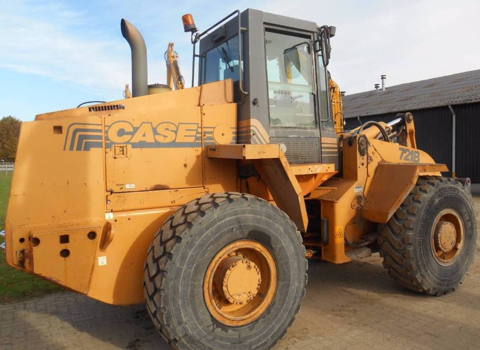
“Case 621C/721C Loader Service Manual” – 824 pages
“6-30480NA – Case 721C Wheel Loader Operator’s Manual” – 288 pages
“6-1231.pdf – Case 621C-721C Loaders Operator’s Manual” – 281 pages
“721C EWD & Hydraulic Schematic.pdf”

Complete workshop & service manual with electrical wiring diagrams for Case 621C/721C Loader. It’s the same service manual used by dealers that guaranteed to be fully functional and intact without any missing page.

This Case 621C/721C Wheeled Loader service & repair manual (including maintenance, overhaul, disassembling & assembling, adjustment, tune-up, operation, inspecting, diagnostic & troubleshooting…) is divided into different sections. Each section covers a specific component or system with detailed illustrations. A table of contents is placed at the beginning of each section. Pages are easily found by category, and each page is expandable for great detail. The printer-ready PDF documents work like a charm on all kinds of devices.

EXCERPT:
INFORMATION AND DIAGNOSTIC CENTER
Many of the machine functions can be displayed on the Programmable Information Center. It can be programmed to display all functions, or only the functions important to the operator. The following functions can be displayed on the Information Center, refer to Figure 2:
FIGURE 2. INFORMATION CENTER AND TRANSMISSION DISPLAY
1. DIRECTION (F-N-R) 4. REQUESTED GEAR (1, 2, 3, 4)
2. TRANSMISSION DISPLAY 5. ACTUAL GEAR BARS
3. DISPLAY CENTER 6. TRANSMISSION MODE (A OR BLANK)
Hourmeter
The hourmeter displays the accumulated running time of the engine in hours and tenths of an hour with an “hour glass” symbol.
Tachometer
The tachometer displays the engine speed in revolutions per minute along with a “r/min” symbol.
Speedometer
The speedometer displays the ground speed in either kilometers per hour (km/h) or miles per hour (mph) along with either a “km/h” or “mph” symbol.
Engine Coolant Temperature
Displays the engine coolant temperature in Celsius with the engine coolant temperature bar graph flashing. See page 10 for a detailed description of the bar graph function.
Engine Oil Pressure
Displays the engine oil pressure in kilopascals (kPa) with the engine oil pressure bar graph flashing. See page 10 for a detailed description of the bar graph function.
Fuel Level
Displays the fuel level in percent remaining in the tank with the fuel level bar graph flashing. See page 10 for a detailed description of the bar graph function.

Posted on

Case 621B, 721B Loaders Workshop Repair & Service Manual


Download Link

INSTANT DOWNLOAD (add to cart)


Case 621B, 721B Loaders Workshop Repair & Service Manual

1,860 pages, bookmarked, Searchable, Printable, high quality PDF

621B, 721B Loaders Service Manual.pdf
621 B 6T-590; 721 B 6T-830

Complete digital official shop manual contains service, maintenance, and troubleshooting information for the Case 621B, 721B Loaders. Diagnostic and repair procedures are covered in great detail to repair, maintain, rebuild, refurbish or restore your Case 621B, 721B Loaders like a professional mechanic in local service/repair workshop. This cost-effective quality manual is 100% complete and intact as should be without any missing pages. It is the same factory shop manual used by dealers that guaranteed to be fully functional to save your precious time.

This manual for Case 621B, 721B Loaders is divided into different sections. Each section covers a specific component or system and, in addition to the standard service procedures, includes disassembling, inspecting, and assembling instructions. A table of contents is placed at the beginning of each section. Pages are easily found by category, and each page is expandable for great detail. It is in the cross-platform PDF document format so that it works like a charm on all kinds of devices. You do not need to be skilled with a computer to use the manual.

EXCERPT:

STEP 80
Measure the cylinder sleeve bore for taper as follows:
1. Measure the bore parallel to the crankshaft at the top end of the ring travel zone.
2. Measure the bore in the same position at the bottom end of the ring travel zone.
3. Measure the bore at right angles to the crankshaft at the top end of the ring travel zone.
4. Measure the bore in the same position at the bottom end of the travel zone.
Compare the results of the measurements (1) and (3) with (2) and (4), to find out if the bore has taper. To measure use a inside micrometer, bore gauge or taper gauge. If the taper is more than 0.04 mm, the cylinder sleeve must be replaced.
STEP 81
Measure the cylinder sleeve bores for out-of-round as follows:
1. Measure the bore parallel to the crankshaft at the top end of the ring travel.
2. Measure the bore in the same position at the bottom end of the ring travel.
3. Measure the bore at right angles to the crankshaft at the top end of the ring travel.
4. Measure the bore in the same position at the bottom end of the ring travel.
Compare the measurements (1) and (3) to find the outof-round wear at the top end of the bore.
Compare the measurements (2) and (4) to find the outof-round wear at the bottom of the bore.
If out-of-round is more than 0.04 mm, the cylinder sleeve must be replaced.
Removing the Cylinder Sleeves
IMPORTANT: Cover the crankshaft journals with a clean cloth. Foreign material from the cylinder sleeve or the cylinder block will cause damage to the crankshaft.
STEP 82
Install a sleeve puller to remove the cylinder sleeve. Position the puller in the sleeve. Make sure that the jaws of the puller do not contact the four block lugs. Tighten the lock bar against the cylinder sleeve.
IMPORTANT: Make sure that the jaws of the sleeve puller do not contact the block lugs.
STEP 83
Carefully turn the bearing nut until the cylinder sleeve is loose from the cylinder block.
STEP 84
Remove the cylinder sleeve from the cylinder block.
Remove the a-ring from the cylinder sleeve.

Posted on

Case 595SLE, 595LSP Loader Backhoe Factory Service & Shop Manual


Download Link

INSTANT DOWNLOAD (add to cart)


Case 595SLE, 595LSP Loader Backhoe Factory Service & Shop Manual

1,000+ pages, bookmarked, Searchable, Printable, high quality PDF
7-22470GB – 595SLE, 595LSP Loader Backhoe Service Manual.pdf – 536 pages
7-22470GB – 595SLE (Super LE), 595LSP Loader Backhoe Service Manual.pdf – 580 pages
7-26630GB – 595 SLE, 595 LSP Training Manual.pdf – 44 pages
7-26620GB – 595LE:SLE:LSP Electrical Schematic:Wiring Diagram.pdf – 195 pages

Complete workshop & service manual with electrical wiring diagrams for Case 595SLE, 595LSP Loader Backhoe. It’s the same service manual used by dealers that guaranteed to be fully functional and intact without any missing page.

This Case 595SLE, 595LSP Loader Backhoe service & repair manual (including maintenance, overhaul, disassembling & assembling, adjustment, tune-up, operation, inspecting, diagnostic & troubleshooting…) is divided into different sections. Each section covers a specific component or system with detailed illustrations. A table of contents is placed at the beginning of each section. Pages are easily found by category, and each page is expandable for great detail. The printer-ready PDF documents work like a charm on all kinds of devices.

EXCERPT:
595SLE/595LSP LOADER BACKHOE SERVICE MANUAL
Table of contents
DIVISION/SECTION SECTION N° REFERENCE N°
1 GENERAL
Standard torque specifications and loctite product chart …1001 7-79451GB
Fluids and lubricants …1002 7-22480GB
2 ENGINE
Engine and radiator removal and installation…2000 7-21290GB
Specifications details …2401 7-26610GB
3 FUEL SYSTEM
4 ELECTRICAL
Electrical schematic …4001 7-26620GB
Battery…4003 7-21330GB
Starter motor …4004 7-21340GB
Removal and installation of electrical components …4005 7-21350GB
Alternator …4007 7-23790GB
Steering, loader and backhoe calibration…4008 7-26530GB
5 STEERING
Removal and installation of steering components …5000 7-23810GB
Steering specifications, pressure checks and troubleshooting …5001 7-21900GB
Steering control valve …5002 7-21390GB
Steering cylinder …5003 7-21400GB
Front axle, four wheel drive machine/four wheel steer machine…5007 7-21890GB
6 POWER TRAIN
Removal and installation of power train components …6000 7-22540GB
Transmission specifications, pressure checks and troubleshooting …6002 7-21430GB
Wheels and tyres …6003 7-22550GB
Gear box …6007 7-22560GB
Rear axle-four whell steer …6008 7-21600GB
7 BRAKES
Removal and installation of brake components …7000 7-23840GB
Disassembly and assembly of brake components…7003 7-23190GB
8 HYDRAULICS
Removal and installation of hydraulic components…8001 7-23210GB
Hydraulic specifications, troubleshooting and pressure checks…8002 7-26630GB
Cleaning the hydraulic system…8003 7-21520GB
Hydraulic pump and unloader valve…8004 7-23250GB
Loader control valve…8005 7-23280GB
Cylinders …8006 7-26120GB
Backhoe control valve…8007 7-23290GB
Extending dipperstick control valve…8008 7-21560GB
Priority demand valve …8010 7-21570GB
9 MOUNTED/EQUIPMENT
Pedals and levers …9001 7-23360GB
Loader…9006 7-26140GB
Cab and Rops …9007 7-26600GB
Backhoe …9008 7-26710GB
Seat and seat belt …9009 7-23830GB
Removal and installation of components …9011 7-23850GB

THROTTLE ADJUSTMENT
Adjustment procedure
1. Park the machine on a level surface.
2. Switch off the engine.
3. Move the hand throttle lever to the max. rpm position.
4. Check that the throttle lever on the engine fuel pump is in contact with the top screw (9).
5. If the throttle lever is not in contact with the stop screw (9), adjust the length of the cable (5) using the locknuts (6) at the throttle bracket (7).
6. Set the throttle pedal (1) to the max. rpm position and hold it there.
7. Check that the gap between the throttle pedal (1) and the stop bolt (11) on the mounting bracket (10) is less than 0 to 0.5 mm.
8. If the gap between the throttle pedal (1) and the stop bolt (11) is greater than 0 to 0.5 mm adjust the length of the stop bolt (11) to bring the gap within limits.
9. Move the hand throttle lever (2) to the min. rpm position.
10. Start the engine.
11. Check that the engine rpm is between 550 and 750 rpm.
12. If the engine rpm is incorrect, adjust the stop screw on the engine fuel pump to bring the rpm within limits.
13. Make sure that the hand throttle lever (2) is in contact with the stop on the hand throttle assembly.

Posted on

Case 590 Loader Backhoe Factory Service & Shop Manual


Download Link

INSTANT DOWNLOAD (add to cart)


OLYMPUS DIGITAL CAMERA

Case 590 Loader Backhoe Factory Service & Shop Manual

1,128 pages, bookmarked, Searchable, Printable, high quality PDF
Case 590 Loader Backhoe Service Manual; 1,128 pages

Complete workshop & service manual with electrical wiring diagrams for Case 590 Loader Backhoe. It’s the same service manual used by dealers that guaranteed to be fully functional and intact without any missing page.

This Case 590 Loader Backhoe service & repair manual (including maintenance, overhaul, disassembling & assembling, adjustment, tune-up, operation, inspecting, diagnostic & troubleshooting…) is divided into different sections. Each section covers a specific component or system with detailed illustrations. A table of contents is placed at the beginning of each section. Pages are easily found by category, and each page is expandable for great detail. The printer-ready PDF documents work like a charm on all kinds of devices.

EXCERPT:
Inspection
1. Discard the parts that were removed from the gland, piston rod assembly, and the tube (10).
2. Clean all parts in cleaning solvent.
3. Inspect the gland, piston rod assembly, and the tube for damage and wear. These parts are not serviced separately, if these parts need to be replaced, a new steering cylinder must be used.
Assembly
See the cross sectional view of the steering cylinder on page 10.
1. Install a new seal (4) in the gland (5). The lip of the seal (4) must be toward the inside of the gland (5).
2. Install a new backup ring (3) next to the gland (5).
3. Install a new wiper (2) in the gland (5). The lip of the wiper (2) must be toward the outside of the gland (5).
4. Install a new 0-ring (6) in the groove on the outside of the gland (5).
5. Fasten the piston rod assembly (7) in a vise with soft jaws.
6. Install a new backup ring (14) in the center groove of the piston rod assembly (7).
7. Install a new seal (8) on top of the backup ring (14) in the center groove of the piston rod assembly (7).
8. Install a new wear ring (9) in the groove on each side of the seal (8).
9. Lubricate the seal (8) and wear rings (9) with clean oil.
Use a piston ring compression tool to hold the new wear rings (9) in place.
10. Start the tube (10) onto the piston rod assembly (7). Push the tube (1 0) onto the piston rod assembly (7) until the compression tool is pushed off the piston rod assembly (7). Be careful not to damage the wear rings (9) and the seal (8).
11. Fasten the tube (10) in a vise with soft jaws. Push the piston rod assembly (7) all the way into the tube (10).
12. Lubricate the wiper (2), backup ring (3), seal (4), and 0-ring (6) on the gland (5) with clean oil.
13. Install the gland (5) on the piston rod assembly (7) and push the gland (5) against the tube (10).

Posted on

John Deere 310J Backhoe Loader Technical Manual (Operation & Test) (TM10846)


Download Link

INSTANT DOWNLOAD (add to cart)


1,001 pages, bookmarked, Searchable, Printable, high quality PDF

TM10846 – 310J Backhoe Loader Operation & Test Manual
TABLE OF CONTENTS
Foreword
9000 – General Information
9001 – Diagnostic Trouble Codes (DTC)
9005 – Operational Checkout Procedure
9010 – Engine
9015 – Electrical System
9020 – Power Train
9025 – Hydraulic System
9031 – Heating and Air Conditioning

Complete Technical manual (Operation & Test Manual) for John Deere 310J Backhoe Loader. It’s the same manual used by dealers that guaranteed to be fully functional and intact without any missing page. This service manual divided into different sections. Each section covers a specific component or system with detailed illustrations. A table of contents is placed at the beginning of each section. Pages are easily found by category, and each page is expandable for great detail. The printer-ready PDF documents work like a charm on all kinds of devices.

EXCERPT:
Mechanical Front Wheel Drive (MFWD) Gear and Pinion Check
Action:
Drive machine at transport speed with mechanical front wheel drive (MFWD) engaged, then disengage.
LISTEN: Does mechanical front wheel drive (MFWD) “whine” when disengaged?
NOTE:
It is normal for mechanical front wheel drive (MFWD) to “whine” when engaged at transport speeds.
Result:
YES: Go to next check.
NO: If mechanical front wheel drive (MFWD) “whines”, check oil levels and fill to correct level.
24 Ride Control System Check (If Equipped)
Action:
Run engine at slow idle.
Turn ride control ON.
Raise loader boom to maximum height.
Power boom down half-way to the ground.
Stop suddenly by releasing the joystick.
LOOK: Is boom cushioned when joystick is released?