INSTANT DOWNLOAD (add to cart)
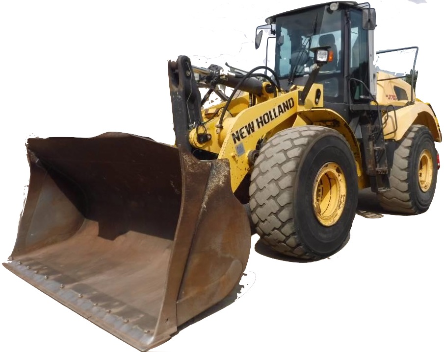
Complete workshop & service manual with electrical wiring diagrams for New Holland Wheel Loader W270, W270B. It’s the same service manual used by dealers that guaranteed to be fully functional and intact without any missing page.
This New Holland Wheel Loader W270, W270B service & repair manual (including maintenance, overhaul, disassembling & assembling, adjustment, tune-up, operation, inspecting, diagnostic & troubleshooting…) is divided into different sections. Each section covers a specific component or system with detailed illustrations. A table of contents is placed at the beginning of each section. Pages are easily found by category, and each page is expandable for great detail. The printer-ready PDF documents work like a charm on all kinds of devices.
1,258 pages, bookmarked, Searchable, Printable, high quality PDF
604.07.229.50 – W190 – W230 – W270 Flat Rate Time Manual.pdf
604.13.512.01 – W270 Workshop Manual.pdf
87661531 – W270B Workshop Manual.pdf
EXCERPT:
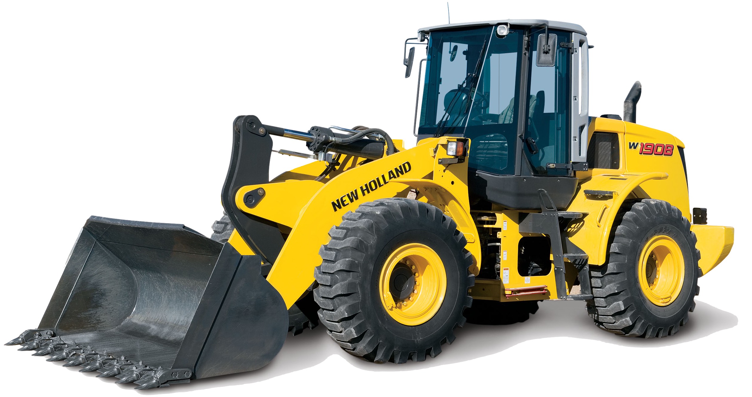
W270B Wheel Loader
Service Manual
87661531
Table of Contents
Description Section No.
General Tab 1
Section Index – General
Standard Torque Specifications 1001
Fluids and Lubricants 1002
Metric Conversion Chart 1003
Engines Tab 2
Section Index – Engines
Engine and Radiator Removal and Installation 2000
Aftercooler 2003
Fuel System Tab 3
Section Index – Fuel System
For Fuel System Repair, See the Engine Service Manual
Electrical Tab 4
Section Index – Electrical
Removal and Installation of Starter and Alternator 4001
Electrical Specifications and Troubleshooting 4002
Batteries 4003
Instrument Cluster 4005
Steering Tab 5
Section Index – Steering
Removal and Installation of Steering Components 5001
Steering Specifications, Pressure Checks, and Troubleshooting 5002
Steering Cylinders 5005
Center Pivot 5006
Auxiliary Steering Motor and Pump 5007
Power Train Tab 6
Section Index – Power Train
Removal and Installation of Power Train Components 6001
Transmission Specifications, Pressure Checks, and Troubleshooting 6002
Transmission 6003
Front and Rear Axle 6004
Drive Shafts, Center Bearing, and Universal Joints 6005
Wheels and Tires 6006
Transmission Control Valve 6007
Brakes Tab 7
Section Index – Brakes
Removal and Installation of Brake Components 7001
Hydraulic Brake Troubleshooting 7002
Brake Accumulators 7004
Parking Brake 7008
Hydraulics Tab 8
Section Index – Hydraulics
Removal and Installation of Hydraulic Components 8001
Hydraulic Specifications, Troubleshooting, and Pressure Checks 8002
Cleaning the Hydraulic System 8003
Hydraulic Pump 8004
Loader Control Valve 8005
Cylinders 8006
Pilot Pressure Accumulator and Ride Control Accumulator 8013
Ride Control Valve 8014
Mounted Equipment Tab 9
Section Index – Mounted Equipment
Air Conditioning Troubleshooting and System Checks For Systems with HFC-134a Refrigerant 9002
Air Conditioner System Service 9003
Removal and Installation of Air Conditioning and Heater Components 9004
Loader 9006
ROPS Cab and ROPS Canpoy 9007
Cab Glass Installation 9010
Electrical Schematic Foldouts and Hydraulic Schematic Foldout In Rear Pocket
…
Disassembly
STEP 1
Remove all dirt, oil, and grease from the exterior of the equipment pump.
STEP 2
Put alignment marks on the end cover and housing.
…