Posted on

New Holland 5640, 6640, 7740, 7840, 8240, 8340 Tractors Factory Service & Shop Manual


Download Link

INSTANT DOWNLOAD (add to cart)



Complete workshop & service manual with electrical wiring diagrams for Ford New Holland 40 Series (5640, 6640, 7740, 7840, 8240, 8340) Tractors. It’s the same service manual used by dealers that guaranteed to be fully functional and intact without any missing page.

This Ford New Holland 40 Series (5640, 6640, 7740, 7840, 8240, 8340) Tractors service & repair manual (including maintenance, overhaul, disassembling & assembling, adjustment, tune-up, operation, inspecting, diagnostic & troubleshooting…) is divided into different sections. Each section covers a specific component or system with detailed illustrations. A table of contents is placed at the beginning of each section. Pages are easily found by category, and each page is expandable for great detail. The printer-ready PDF documents work like a charm on all kinds of devices.

1,452 pages, bookmarked, Searchable, Printable, high quality PDF
840564061 – Ford New Holland 40 Series (5640, 6640, 7740, 7840, 8240, 8340) Tractors Service Manual
Part number 840564061 English
Ford New Holland 5640, 6640, 7740, 7840, 8240, 8340 Tractors Repair Manual

EXCERPT:
8. HYDRAULIC CIRCUIT DESCRIPTION
The circuits provided with oil by the transmission mounted hydraulic pumps can be separated into the following categories:
Tractors With Closed Centre Load Sensing Variable Displacement Hydraulic Pump:
• High pressure circuit oil up to a maximum pressure of 2800 lbf/in2 (193 bar) for operation of the hydraulic lift assembly, remote control valves and auxiliary hydraulic equipment, where fitted.
• Low pressure circuit oil for operation of the 16 x 16 transmission control circuits, PTO, differential lock, electronic draft control valve pilot pressure and four wheel drive circuits, where fitted.
• Hydrostatic steering system oil up to a maximum pressure of 2500 lbf/in2 (172 bar) which is then regulated to provide low pressure oil for lubrication of the PTO and 16 x 16 transmission.
Tractors With Fixed Displacement Tandem Gear Type Pump:
• High pressure oil up to a maximum pressure of 2650 lbf/in2 (183 bar) for operation of the hydraulic lift assembly, remote control valves and auxiliary hydraulic equipment, where fitted.
• Hydrostatic steering system oil up to a maximum pressure of 2500 lbf/in2 (172 bar) which is then regulated to provide low pressure oil for operation of the PTO, four wheel drive disengagement system, differential lock and lubrication of 12 x 12 transmission synchronizers, bearings, output shaft and PTO.
The basic hydraulic circuits for each type of installation are shown in schematic format in Figure 7, Figure 8 and Figure 9 of this Chapter.
For a detailed description and operation of the high pressure hydraulic lift circuits on Series 40 tractors refer to the following Chapters in this Part of the Repair Manual.
For tractors installed with the variable displacement hydraulic pump and electronic draft control, refer to Chapters 2 and 3.
For tractors installed with the variable displacement hydraulic pump and top link sensing, refer to Chapters 2 and 4.
For tractors installed with fixed displacement gear type hydraulic pumps, refer to Chapter 5.
For the hydraulic operation of the transmission, PTO, differential lock, steering and four wheel drive disengagement systems, refer to the appropriate Part and Chapters of this Repair Manual which describe the operation of the component.

Posted on

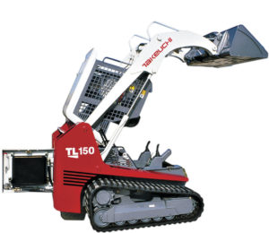
Takeuchi Crawler Loader TL150 Factory Service & Shop Manual


Download Link

INSTANT DOWNLOAD (add to cart)

Complete workshop & service manual with electrical wiring diagrams for Takeuchi Crawler Loader TL150. It’s the same service manual used by dealers that guaranteed to be fully functional and intact without any missing page.

This Takeuchi Crawler Loader TL150 service & repair manual (including maintenance, overhaul, disassembling & assembling, adjustment, tune-up, operation, inspecting, diagnostic & troubleshooting…) is divided into different sections. Each section covers a specific component or system with detailed illustrations. A table of contents is placed at the beginning of each section. Pages are easily found by category, and each page is expandable for great detail. The printer-ready PDF documents work like a charm on all kinds of devices.

798 pages, bookmarked, Searchable, Printable, high quality PDF
Takeuchi Crawler Loader TL150 Workshop Manual; 798 pages; Serial Number: 21500004~.

EXCERPT:
I . GENERAL
II . SPECIFICATIONS
III. MACHINE CONFIGURATION
IV . HYDRAULIC UNITS
V . TROUBLESHOOTING VI. ENGINE

Adjusting the Main Relief Valve Pressure
1. Install a pressure gauge in the following pressure sensor port.
• Control valve pressure sensor port.
“II. Specifications, Standards for Judging Performance”
2. Run the pump at the rated speed.
3. Operate the control valve’s cylinder spool over its full stroke and read the value indicated by the pressure gauge.
4. Turn the set screw (1) while watching the pressure gauge to adjust.
Turning it to the right increases the set pressure. Turning it to the left decreases the set pressure.
5. After completing the pressure adjustment, tighten the lock nut (2) while holding the set screw (1) so it won’t turn.
Operate the relief valve again and check if the pressure is stabilized.

Posted on

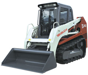
Takeuchi Crawler Loader TL140 Factory Service & Shop Manual


Download Link

INSTANT DOWNLOAD (add to cart)

Complete workshop & service manual with electrical wiring diagrams for Takeuchi Crawler Loader TL140. It’s the same service manual used by dealers that guaranteed to be fully functional and intact without any missing page.

This Takeuchi Crawler Loader TL140 service & repair manual (including maintenance, overhaul, disassembling & assembling, adjustment, tune-up, operation, inspecting, diagnostic & troubleshooting…) is divided into different sections. Each section covers a specific component or system with detailed illustrations. A table of contents is placed at the beginning of each section. Pages are easily found by category, and each page is expandable for great detail. The printer-ready PDF documents work like a charm on all kinds of devices.

559 pages, bookmarked, Searchable, Printable, high quality PDF
Takeuchi Crawler Loader TL140 Workshop Manual; 559 pages; Serial Number: 21400011~.

EXCERPT:
CONTROL VALVE – HYDRAULIC UNITS
DISASSEMBLY AND ASSEMBLY General Cautions
• Since all parts in control valves are precision machined, carry out disassembly and assembly operations in a clean place.
• Before disassembly, clean the outside surfaces around the valves.
• Clean all disassembled parts in cleaning solvent. Use a lint free cloth, or air dry the parts.
• Apply hydraulic oil to sliding surfaces and apply a thin coating of grease to seals when assembling them.
Following is an explanation of the control valve disassembly procedure.
Follow the procedure used to disassemble the control valve in reverse order when reassembling it.
Disassembly
Valve Assembly
1. Loosen the nuts and remove the tie rods, then remove the sections.
Nut: 39.23 ±3.92 N·m
2. Remove the O-ring.
• The mating surfaces are metal seals, so be
careful not to scratch, bruise or otherwise dam- age them.

Posted on

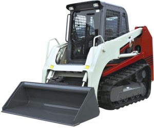
Takeuchi Crawler Loader TL130 Factory Service & Shop Manual


Download Link

INSTANT DOWNLOAD (add to cart)

Complete workshop & service manual with electrical wiring diagrams for Takeuchi Crawler Loader TL130. It’s the same service manual used by dealers that guaranteed to be fully functional and intact without any missing page.

This Takeuchi Crawler Loader TL130 service & repair manual (including maintenance, overhaul, disassembling & assembling, adjustment, tune-up, operation, inspecting, diagnostic & troubleshooting…) is divided into different sections. Each section covers a specific component or system with detailed illustrations. A table of contents is placed at the beginning of each section. Pages are easily found by category, and each page is expandable for great detail. The printer-ready PDF documents work like a charm on all kinds of devices.

712 pages, bookmarked, Searchable, Printable, high quality PDF
Takeuchi Crawler Loader TL130 Workshop Manual; 712 pages; Serial Number: 21300004~.

EXCERPT:
I . GENERAL
II . SPECIFICATIONS
III. MACHINE CONFIGURATION
IV . HYDRAULIC UNITS
V . TROUBLESHOOTING VI. ENGINE

HYDRAULIC UNITS – HST PUMP
2. Remove the charge relief valve.
a. Before removing the screw adjustable relief
valve plug, mark the plug, lock nut (5), and housing so as to approximately maintain the original adjustment when assembling. Remove the screw adjustable charge relief valve plug (6) by loosening the lock nut and unscrewing the plug. Remove the O-ring from the plug (6).
b. Remove the spring (7) and poppet (8) from the housing.
3. Remove the flushing valve.
a. Remove the flushing valve plug (9) from the pump housing. Remove the O-ring from the plug (9).
b. Remove the flushing valve spool (10) assembly from the housing.
4. Remove the flushing relief valve.
a. Remove the flushing relief valve internal hex plug (11) from the pump housing. Remove the O-ring from the plug (11).
b. Remove the spring (13) and poppet (14) from the housing.
c. Do not alter the shims (12) which are installed between the spring and valve plug, or inter- change parts with another valve.

Posted on

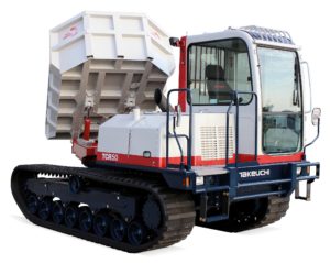
Takeuchi Dump Carrier TCR50 Factory Service & Shop Manual


Download Link

INSTANT DOWNLOAD (add to cart)


Complete workshop & service manual with electrical wiring diagrams for Takeuchi Dump Carrier TCR50. It’s the same service manual used by dealers that guaranteed to be fully functional and intact without any missing page.

This Takeuchi Dump Carrier TCR50 service & repair manual (including maintenance, overhaul, disassembling & assembling, adjustment, tune-up, operation, inspecting, diagnostic & troubleshooting…) is divided into different sections. Each section covers a specific component or system with detailed illustrations. A table of contents is placed at the beginning of each section. Pages are easily found by category, and each page is expandable for great detail. The printer-ready PDF documents work like a charm on all kinds of devices.

302 pages, bookmarked, Searchable, Printable, high quality PDF
Takeuchi Dump Carrier TCR50 Workshop Manual; 302 pages; Serial Number: 30500003~ 30500038~ 30510001~.

EXCERPT:
5. HYDRAULIC SYSTEM
. Remove the swash plate as follows:
Remove the swash plate (10).
• Take care not to damage the sliding surface of the swash plate.
9. Remove the needle bearing assembly as follows: Remove the needle bearing assembly (12) from the servo piston.
10. Remove the valve plate as follows:
Remove the valve plate (13) from the housing.
• If the valve plate is hard to remove, use a flat head driver.
• Take care not to damage the valve plate.
11. Remove the timing pin.
Remove the timing pin (14) of the valve plate.
12. Remove the servo cover (15) as follows:
(1) Remove the five cap screws.
(2) Remove the servo cover (15) and gasket (17).