Posted on

Takeuchi Compact Excavator TB1140 Factory Service & Shop Manual


Download Link

INSTANT DOWNLOAD (add to cart)
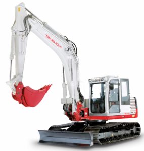


Complete workshop & service manual with electrical wiring diagrams for Takeuchi Compact Excavator TB1140. It’s the same service manual used by dealers that guaranteed to be fully functional and intact without any missing page.

This Takeuchi Compact Excavator TB1140 service & repair manual (including maintenance, overhaul, disassembling & assembling, adjustment, tune-up, operation, inspecting, diagnostic & troubleshooting…) is divided into different sections. Each section covers a specific component or system with detailed illustrations. A table of contents is placed at the beginning of each section. Pages are easily found by category, and each page is expandable for great detail. The printer-ready PDF documents work like a charm on all kinds of devices.

652 pages, bookmarked, Searchable, Printable, high quality PDF
Takeuchi Compact Excavator TB1140 Workshop Manual; 652 pages; Serial Number: 51400007~.

EXCERPT:
I . GENERAL
II . SPECIFICATIONS
III. MACHINE CONFIGURATION
IV . HYDRAULIC UNITS
V . TROUBLESHOOTING VI. ENGINE

UPPER FRAME – MACHINE CONFIGURATION
Removing the Cab
1. Disconnect the battery ground cable from the battery.
2. Remove the operator seat from the bracket.
3. Remove the cover R (1), L (2) and C (3), then remove bracket (4) from cover C (3).
4. Remove the cover R (5), then disconnect the speaker cords.
5. Remove the cover L (6), then disconnect the speaker cords and duct hose (7) from cover L (6).
6. Remove the duct hose (8) from air conditioner unit (9)
7. Remove the installation bolts, remove the box (10) from cab.
8. Disconnect the wiring (11) to the cab.
9. Disconnect the hose (12) from sub tank.
10. Loosen the seat bracket installation bolts (13) [four].
11. Remove installation bolts (14) [six], then hoist and remove the cab.
• Be sure to hoist the cab carefully by sliding the seat so as not to hit the cab. Cab: 370 kg
Installing the Cab
Follow the procedure used for removal in reverse order.
• Suspend the cab temporarily, keeping it level, and fasten it temporarily while it is still suspended.

Posted on

Takeuchi Compact Excavator TB180FR Factory Service & Shop Manual


Download Link

INSTANT DOWNLOAD (add to cart)

Complete workshop & service manual with electrical wiring diagrams for Takeuchi Compact Excavator TB180FR. It’s the same service manual used by dealers that guaranteed to be fully functional and intact without any missing page.

This Takeuchi Compact Excavator TB180FR service & repair manual (including maintenance, overhaul, disassembling & assembling, adjustment, tune-up, operation, inspecting, diagnostic & troubleshooting…) is divided into different sections. Each section covers a specific component or system with detailed illustrations. A table of contents is placed at the beginning of each section. Pages are easily found by category, and each page is expandable for great detail. The printer-ready PDF documents work like a charm on all kinds of devices.

686 pages, bookmarked, Searchable, Printable, high quality PDF
Takeuchi Compact Excavator TB180FR Workshop Manual; 686 pages; Serial Number: 17830004~.

EXCERPT:
I . GENERAL
II . SPECIFICATIONS
III. MACHINE CONFIGURATION IV. HYDRAULIC UNITS
V . TROUBLESHOOTING VI. ENGINE

HYDRAULIC UNITS – HYDRAULIC PUMP
Assembly
1. Install the set screw (2).
• Fix the set screw (2) to the same length as previously assembled using the lock nut (3). Lock Nut: 98 N·m
2. Install the piston.
3. Install the drain plug (1).
4. Install the oil seal.
5. Install the shaft in the housing.
• Tap the spline end with a plastic hammer to positively install the outer race of the bearing in the housing hole.
6. Fit the pin R and L on the swash plate.
7. Install the swash plate in the housing.
• Insert the bushing into the swash plate.
• Apply grease on the sliding surfaces of the swash plate, pin R and pin L.
8. Mount the pin and tighten the plug. Plug: 110 N·m.
9. Mount the piston in the housing.

Posted on

Takeuchi Compact Excavator TB175 Factory Service & Shop Manual


Download Link

INSTANT DOWNLOAD (add to cart)


Complete workshop & service manual with electrical wiring diagrams for Takeuchi Compact Excavator TB175. It’s the same service manual used by dealers that guaranteed to be fully functional and intact without any missing page.

This Takeuchi Compact Excavator TB175 service & repair manual (including maintenance, overhaul, disassembling & assembling, adjustment, tune-up, operation, inspecting, diagnostic & troubleshooting…) is divided into different sections. Each section covers a specific component or system with detailed illustrations. A table of contents is placed at the beginning of each section. Pages are easily found by category, and each page is expandable for great detail. The printer-ready PDF documents work like a charm on all kinds of devices.

978 pages, bookmarked, Searchable, Printable, high quality PDF
Takeuchi Compact Excavator TB175 Workshop Manual; 978 pages; Serial Number: 17510003~.

EXCERPT:
I . GENERAL
II . SPECIFICATIONS
III. MACHINE CONFIGURATION
IV . HYDRAULIC UNITS
V . TROUBLESHOOTING VI. ENGINE

HYDRAULIC UNITS – PILOT VALVE

OPERATION
The pilot valve casing contains a vertical shaft hole with a reducing valve incorporated into it. When the handle is tilted, the push rod and spring seat are pushed down changing the secondary pressure spring’ s pressure.
The casing provides the inlet port P (the primary pressure) and the tank port T. The secondary pressure commensurate with the variation of the operation angle of the handle (1) is taken out through the output ports A and B below the vertical shaft hole. The secondary pressure functions as the pilot pressure to actuate the spool of the control valve (2).
When the Handle (1) is at the Neutral Position:
The force of the spring (3) for setting the secondary pressure that determines the output pressure of the pilot valve is not conveyed to the spool (4). Therefore, the spool (4) is pushed up by the return spring (5), and the output ports A and B are connected with the tank port T, making the pressures in the ports A and B equal to the pressure in the tank port T.
When the Handle (1) is Tilted:
When the handle (1) is tilted and the push rod (6) is pushed, the spool (4) moves downward and the input port P is connected with the output port A. Then, the oil from the pilot pump flows into the output port A, generating a pressure.

Posted on

Takeuchi Compact Excavator TB153FR Factory Service & Shop Manual


Download Link

INSTANT DOWNLOAD (add to cart)


Complete workshop & service manual with electrical wiring diagrams for Takeuchi Compact Excavator TB153FR. It’s the same service manual used by dealers that guaranteed to be fully functional and intact without any missing page.

This Takeuchi Compact Excavator TB153FR service & repair manual (including maintenance, overhaul, disassembling & assembling, adjustment, tune-up, operation, inspecting, diagnostic & troubleshooting…) is divided into different sections. Each section covers a specific component or system with detailed illustrations. A table of contents is placed at the beginning of each section. Pages are easily found by category, and each page is expandable for great detail. The printer-ready PDF documents work like a charm on all kinds of devices.

686 pages, bookmarked, Searchable, Printable, high quality PDF
Takeuchi Compact Excavator TB153FR Workshop Manual; 686 pages; Serial Number TB153FR: 15820004~.

EXCERPT:
I . GENERAL
II . SPECIFICATIONS
III. MACHINE CONFIGURATION IV . HYDRAULIC UNITS
V . TROUBLESHOOTING VI. ENGINE

1. Heater Core
Heater cores are like small radiators. The fin and tube construction is designed to route coolant flow for the best possible heat energy transfer from coolant to cab air. Hoses from and to the engine are connected to the core with clamps. The core outlet may be larger or the same size as the inlet.
2. Water Valves
Water valves may be cable, vacuum or air controlled. The valve can be either open, closed or set part way open. Some valves have a bypass design to return coolant to the engine. Most are manually controlled although electronic systems are now being installed.
3. Defrosters and Ducts
Defrosting is accomplished by directing heated dry air through ducts to the windshield. The heater system serves the dual purpose of defrosting and heating. Controls are used to route the air flow to the windshield and occupant areas by opening and closing duct doors. Controls may be manual, air or vacuum.
Many vehicles use a “defrost interlock” system which utilizes the air conditioner to dry the defrost air and clear the cab windows more quickly.
4. Blowers and Fans
Blowers or fans are used in the system to move cab air through the heater core and evaporator. Air can be pushed or pulled through the core depending on system design. Blower or fan speed is usually selected by the operator.

Posted on

Takeuchi Compact Excavator TB125, TB135, TB145 Factory Service & Shop Manual


Download Link

INSTANT DOWNLOAD (add to cart)


Complete workshop & service manual with electrical wiring diagrams for Takeuchi Compact Excavator TB125, TB135, TB145. It’s the same service manual used by dealers that guaranteed to be fully functional and intact without any missing page.

This Takeuchi Compact Excavator TB125, TB135, TB145 service & repair manual (including maintenance, overhaul, disassembling & assembling, adjustment, tune-up, operation, inspecting, diagnostic & troubleshooting…) is divided into different sections. Each section covers a specific component or system with detailed illustrations. A table of contents is placed at the beginning of each section. Pages are easily found by category, and each page is expandable for great detail. The printer-ready PDF documents work like a charm on all kinds of devices.

1,087 pages, bookmarked, Searchable, Printable, high quality PDF
Takeuchi Compact Excavator TB125, TB135, TB145 Workshop Manual; 1,087 pages; Serial Number TB125: 12510003~, TB135: 13510004~, TB145: 14510004~.

EXCERPT:
I . GENERAL
II . SPECIFICATIONS
III. MACHINE CONFIGURATION
IV. HYDRAULIC UNITS
V . TROUBLESHOOTING VI. ENGINE

HYDRAULIC PUMP
OPERATION
Piston Pump
This pump is a variable displacement piston pump with a single cylinder block, which discharges two equal volumes.
Ten pistons (2) are installed in the cylinder block (1), and the end surface is in contact with the valve plate (3). The suction port C and the discharge port A of the pump P1 and the discharge port B of the pump P2 are arranged in the valve plate (3). On the other hand, the swash plate (4) is fastened to the housing at a given inclination, and the pistons (2) rotate along this swash plate (4).
When the shaft (5) is rotated, the cylinder block (1) rotates, the pistons (2) in the cylinder block execute reciprocating movement along the swash plate (4), and the pump executes suction and discharge. At this time, the pistons in contact with the discharge port A of the valve plate (3) operate as the pump P1, while the pistons in contact with the discharge port B operate as the pump P2.
In this way, the ten pistons (2) execute one suction and discharge stroke with each revolution of the cylinder block (1), so that suction and discharge are executed continuously when the shaft (5) is rotated continuously.
As the piston stroke displacement depends on the inclination of the swash plate (4), the discharge flow quantity can be changed by changing the inclination of the awash plate (4).
HYDRAULIC UNITS