Posted on

1999-2004 Jeep Grand Cherokee (WG/WJ) Workshop Repair & Service Manual (713MB Printable PDF)

Jeep Grand Cherokee (WG_WJ) 1999-2004.jpg
Jeep Grand Cherokee (WG_WJ) 1999-2004

1999-2004 Jeep Grand Cherokee (WG/WJ) Workshop Repair & Service Manual (713MB Printable PDF)


MJPGC9904OPMS.PDF
Price: $29.99 USD

Jeep Grand Cherokee (WG_WJ) 1999-2004 – SAMPLE

This quality manual for 1999-2004 Jeep Grand Cherokee (WG/WJ) is 100% complete and intact, no missing/corrupt pages/sections to freak you out! Buy from responsible seller and get instant download now without surprise; this manual is exactly as described. It is in the cross-platform PDF document format so that it works like a charm on all kinds of devices.

MAKE: Jeep
— — — — — — — — —
MODEL: Grand Cherokee (WG/WJ)
— — — — — — — — —
YEAR: 1999, 2000, 2001, 2002, 2003, 2004
— — — — — — — — —
FOAMR: PDF (713MB)

This is the same type of official service manual your local dealer will use when doing a repair. This manual for 1999-2004 Jeep Grand Cherokee (WG/WJ) has detailed illustrations as well as step by step instructions. All pages are printable, so run off what you need and take it with you into the garage or workshop. These manuals are your number one source for repair and service information. They are specifically written for the do-it-yourself-er as well as the experienced mechanic. Using this repair manual is an inexpensive way to keep your vehicle working properly. Each manual provides step-by-step instructions based on the complete dis-assembly of the machine. It is this level of detail, along with photos and illustrations, that guide the reader through each service and repair procedure.

’00 (108MB PDF)
’01 (155MB PDF)
’01 alternate (70MB PDF)
’02 (94MB PDF)
’03 (170MB PDF)
’99 (EN) (60MB PDF)
’99 (ES) (55MB PDF)

EXCERPTS:

ROTOR DEL FRENO DE DISCO DELANTERO
DESMONTAJE
(1) Eleve y apoye el vehículo.
(2) Retire el conjunto de rueda y neumático.
(3) Retire los pernos de anclaje del calibrador (Fig. 32) y retire el calibrador y el anclaje como un conjunto de la articulación de la dirección.
(4) Asegure el calibrador con alambre a una pieza de la suspensión cercana. No permita que la manguera de freno soporte el peso del calibrador.
(5) Retire los retenes que fijan el motor en los espárragos de la maza.
(6) Retire el rotor de la maza….

3.2.2 LINE PRESSURE CONTROL
Proper control of the transmission line pressure is essential for proper operation. The 45RFE/545RFE normally uses closed loop line pressure control, where actual line pressure (reported by the line pressure sensor) is continuously monitored.
The TCM determines the desired (target) line pressure which is required, and adjusts the Pressure Control Solenoid (PCS) until the actual line pressure matches the desired line pressure value. In the event of a line pressure sensor failure DTC P0932(CA), the TCM changes to an open loop control at an essentially constant line pressure…

MJPGC9904OPMS.PDF
Price: $29.99 USD

Posted on

Kobelco SK450(LC)-6,SK480(LC)-6, SK450(LC)VI,SK480(LC)VI, SK450(LC)-8, SK480LC-8(S) Crawler Excavators Workshop Repair & Service Manual (Printable PDF)

Kobelco SK450(LC)-6,SK480(LC)-6, SK450(LC)VI,SK480(LC)VI, SK450(LC)-8, SK480LC-8(S) Crawler Excavators Workshop Repair & Service Manual (Printable PDF)

Kobelco SK450(LC)-6,SK480(LC)-6, SK450(LC)VI,SK480(LC)VI, SK450(LC)-8, SK480LC-8(S) Crawler Excavators Workshop Repair & Service Manual (Printable PDF)


MKBSK450480OPEK.PDF
Price: $29.99 USD

SK450-480 – SAMPLE

This quality manual for Kobelco SK450-6, SK450LC-6, SK480-6, SK480LC-6, SK450VI, SK450LC-VI, SK480VI, SK480LC-VI, SK450-8, SK450LC-8, SK480LC-8, SK480LC-8S Crawler Excavators is 100% complete and intact, no missing/corrupt pages/sections to freak you out! Buy from responsible seller and get instant download now without surprise; this manual is exactly as described. It is in the cross-platform PDF document format so that it works like a charm on all kinds of devices.

MAKE: Kobelco
MODELS:
CRAWLER EXCAVATORS

“SK450(LC)-6,SK480(LC)-6 (S5LS0009E).pdf”
1,261 pages

“SK450(LC)VI,SK480(LC)VI (S5LS0006E).pdf”
1,120 pages

“SK450(LC)-8,SK480LC-8(S) (S5LS0010E).pdf”
1,132 pages

This is the same type of official service manual your local dealer will use when doing a repair. This manual for Kobelco SK450(LC)-6,SK480(LC)-6, SK450(LC)VI,SK480(LC)VI Crawler Excavators has detailed illustrations as well as step by step instructions. All pages are printable, so run off what you need and take it with you into the garage or workshop. These manuals are your number one source for repair and service information. They are specifically written for the do-it-yourself-er as well as the experienced mechanic. Using this repair manual is an inexpensive way to keep your vehicle working properly. Each manual provides step-by-step instructions based on the complete dis-assembly of the machine. It is this level of detail, along with photos and illustrations, that guide the reader through each service and repair procedure.

EXCERPTS:

2. ESCAPING PROCEDURE IN CASE OF EMERGENCY
2.1 WHEN CAB DOOR DOES NOT OPEN;
(1) Escape from the front window.
(2) Escape from skylight.
(3) When front window and skylight do not open; A life hammer is provided on the right-hand side of the cab at all times. Escape by breaking the glass at the escape label (seal mark) at the back of the cab….

3) Assembling spool and sleeve (Fig. 1-31 CD section)
Assemble spool (652) and sleeve (651) into the spool hole of the casing.
• Make sure that the spool and the sleeve move smoothly in the casing.
• Beware of the direction of the spool.
4) Assembling feedback lever Assemble feedback lever (611). Then put pin (874) into the pin hole of the feedback lever.
• The work is eased if the pin is put in the feedback lever a little, beforehand.
• Take care so as not to mistake the direction of the feedback lever….


MKBSK450480OPEK.PDF
Price: $29.99 USD

Posted on

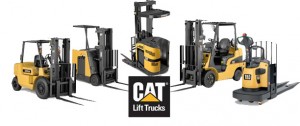
Caterpillar Lift Trucks All Models (MCFE 2011.12) Workshop HPK, OMM, PSB, Service Manual, Parts Sample

Caterpillar Lift Trucks MCFE 2011

Caterpillar Lift Trucks All Models (MCFE 2011.12) Workshop HPK, OMM, PSB, Service Manual, Parts Sample


MCTMCFE01OPES.PDF
Price: $49.99 USD

Caterpillar Lift Trucks MCFE 2011 – SAMPLE

This quality manuals for Caterpillar Lift Trucks MCFE 2011 is 100% complete and intact, no missing/corrupt pages/sections to freak you out! Buy from responsible seller and get instant download now without surprise; this manual is exactly as described. It is in the cross-platform PDF document format so that it works like a charm on all kinds of devices.

*** *** *** *** *** *** *** *** *** ***

MAKE: Caterpillar Lift Trucks
— — — — — — — — —
Publication Type: HPK, OMM, PSB, Service Manual, Parts Sample
— — — — — — — — —
Document Format: PDF [inside Virtual Machine (8.2G Windows XP Pro SP3)]
— — — — — — — — —
MODEL: MCFE (v1.5.0.150; 2011/12/17)
Cushion Tire; Electric Model; Hand Pallet; Large Pneumatic (6 ton – 16 ton); Small Pneumatic (1 ton – 5.5 ton)
Model Numbers:
2EC15 36/48V; 2EC18 36/48V; 2EC20 36/48V; 2EC20 72/80V; 2EC25 36/48V; 2EC25 72/80V; 2EC25E 36/48V; 2EC25E 72/80V; 2EC30 36/48V; 2EC30 72/80V; DP100; DP100N; DP115; DP120N; DP135; DP135N; DP15 FC; DP15 MC; DP150; DP150N; DP15K FC; DP15K MC; DP15N; DP160N; DP18 FC; DP18 MC; DP18K FC; DP18K MC; DP18N; DP20 FC; DP120 MC; DP20CN; DP20K FC; DP20K MC; DP20N; DP25 FC; DP25 MC; DP25K FC; DP25K MC; DP25N; DP30 FC; DP30 MC; DP30K FC; DP30K MC; DP30N; DP35 FC; DP35 MC; DP35K FC; DP35K MC; DP35N; DP40; DP40K; DP40KL; DP40N; DP45; DP45K; DP45N; DP50; DP50CN; DP50K; DP50N; DP55N; DP60; DP70; DP80; DP80N; DP90; DP90N; DPL40; EC15; EC15K; EC15N; EC18K; EC18N; EC20K; EC20N; EC25EN; EC25K; EC25KE; EC25KL; EC25LN; EC25N; EC30K; EC30N; EC35N; EC40N; EC45N; EC55N; EP10KRT; EP10KRT PAC; EP12KRT; EP12KRT PAC; EP13T 24V; EP13T 36V; EP13T 48V; EP15KRT; EP15KRT PAC; EP15T 24V; EP15T 36V; EP15T 48V; EP16 36/48V MCII; EP16 36/48V MCIII; EP16 72/80V MCII; EP16 72/80V MCIII; EP16K; EP16KT; EP16N; EP16NT; EP18 36/48V MCII; EP18 36/48V MCIII; EP18 72/80V MCII; EP18 72/80V MCIII; EP18K; EP18KT; EP18N; EP18NT; EP18T 36V; EP18T 48V; EP20 36/48V MCII; EP20 36/48V MCIII; EP20 72/80V MCII; EP20 72/80V MCIII; EP20CN; EP20K; EP20K PAC; EP20KC; EP20KT; EP20NT; EP20T 36V; EP20T 48V; EP25 36/48V MCII; EP25 36/48V MCIII; EP25 72/80V MCII; EP25 72/80V MCIII; EP25K; EP25K PAC; EP30 36/48V MCII; EP30 36/48V MCIII; EP30 72/80V MCII; EP30 72/80V MCIII; EP30K; EP30K PAC; EP35K; EP35K PAC; EP40; EP45; EP50; F25; F30; F35; F40D; F40D P; F40D SA; F50D; F50D P; F50D SA; F60D; F60D P; F60D SA; FC40; GC15; GC15K-GAS; GC15K-LP; GC18; GC18K-GAS; GC18K-LP; GC20; GC20HP; GC20K HP; GC20K-GAS; GC20K-LP; GC20N; GC25; GC25HP; GC25K HP; GC25K-GAS; GC25K-LP; GC25N; GC28N; GC30; GC30K-GAS; GC30K-LP; GC30N; GC35K; GC40K; GC40K STR; GC40K SWB; GC45K; GC45K STR; GC45K SWB; GC55K; GC55K STR; GC60K; GC70K; GC70K STR; GP15 FC; GP15 MC; GP15K FC; GP15K MC; GP15N; GP15ZN; GP18 FC; GP18 MC; GP18K FC; GP18K MC; GP18N; GP18ZN; GP20 FC; GP20 MC; GP20CN; GP20HN; GP20K FC; GP20K MC; GP20N; GP20ZN; GP25 FC; GP25 MC; GP25HN; GP25K FC; GP25K MC; GP25N; GP25ZN; GP30 FC; GP30 MC; GP30K FC; GP30K MC; GP30N; GP35 FC; GP35 MC; GP35K FC; GP35K MC; GP35N; GP40; GP40K; GP40KL; GP40N; GP45K; GP45N; GP50CN; GP50K; GP50N; GP55N; GPE15N; GPE15ZN; GPE18N; GPE18ZN; GPE20CN; GPE20N; GPE20ZN; GPE25N; GPE25ZN; GPE30N; GPE35N; GPL40; GS-CAT; GT-CAT; M100B; M100D; M100D 36/48V; M100D 72/80V; M120D; M120D 36/48V; M120D 72/80V; M25D; M30D; M35D; M40D; M40D P; M40D SA; M50D; M50D P; M50D SA; M60B; M70B; M70D; M80B; M80D; MC40D; MC60D P; MC60D SA; T100D; T25D; T30D; T40D; T40E; T50D; T50E; T60D; T60E; T70D; T80D; T90D; TC100D; TC400D; TC60D; V100F; V110C; V135C; V155C; V165VC; V180C; V200C; V200C STR; V225C; V25D; V265C; V300C; V30D; V40D; V40D SA; V40E; V50D; V50D SA; V50E; V60E; V70E; V70F; V80E; V80F; V90E; V90F; VC110F; VC40D; VC60D; VC60D SA; VC60E


MCTMCFE01OPES.PDF
Price: $49.99 USD

Posted on

SsangYong Rodius 2004-2015 Workshop Repair & Service Manual (1.2GB PDF)

SsangYong Rodius 2004-2015 Workshop Repair & Service Manual (1.2GB PDF)

SsangYong Rodius 2004-2015 Workshop Repair & Service Manual (1.2GB PDF)


MSYRD0415OPES.pdf
Price: $24.99 USD

SsangYong Rodius 2004-2015 – SAMPLE

This is the same type of official service manual your local dealer will use when doing a repair. This manual has detailed illustrations as well as step by step instructions. All pages are printable, so run off what you need and take it with you into the garage or workshop. These manuals are your number one source for repair and service information. They are specifically written for the do-it-yourself-er as well as the experienced mechanic. Using this repair manual is an inexpensive way to keep your vehicle working properly. Each manual provides step-by-step instructions based on the complete dis-assembly of the machine. It is this level of detail, along with photos and illustrations, that guide the reader through each service and repair procedure.

This quality manual for SsangYong Rodius 2004-2015 is 100% complete and intact, no missing/corrupt pages/sections to freak you out! Buy from responsible seller and get instant download now without surprise; this manual is exactly as described. It is in the cross-platform PDF document format so that it works like a charm on all kinds of devices.

This complete official full workshop service repair manual includes:
* Instructions guide you through every repair procedure step by step.
* Detailed sub-steps expand on repair procedure information
* Notes, cautions and warnings throughout each chapter pinpoint critical information.
* Bold figure number help you quickly match illustrations with instructions.
* Detailed illustrations, drawings and photos guide you through every procedure.
* Enlarged inset helps you identify and examine parts in detail.
* Troubleshooting and electrical service procedures are combined with detailed wiring diagrams for ease of use.

EXCERPTS:

Functions
When the engine is running, the camshaft rotates the intake camshaft hydrauically/mechanically relative to the camshaft sprocket by 34° crankangle to the ‘advanced’ position and back to the ‘retarded’ position.
The camshaft adjuster is actuated electromechanically by the ECU. The positioning time of approx. 1 second is dependent on the engine oil pressure at the camshaft adjuster and on the oil viscosity and oil temperature, respectively. The position indicator (b)
on the camshaft sprocket (13) provides the camshaft rotational speed to the position sensor (9) as an input parameter for the engine ignition control unit….

Adjustment Procedure
1. Position the No.1 cylinder to BTDC 30° .
2. Remove the chain tensioner.
3. Remove the exhaust camshaft sprocket.
4. Align the intake and exhaust camshaft flange hole with the cylinder head upper surface.
• Intake Side : 3 o’clock direction
• Exhaust Side : 9 o’clock direction
5. Align the holes on intake and exhaust camshaft to the hole on cylinder head. Insert the holding pin DW 110-120 into the hole.
6. Secure the intake and exhaust camshaft.
7. Position the piston of No.1 cylinder at TDC (OT) by turning the crankshaft.
8. Turn the camshaft adjuster of the intake camshaft
to the left as much as possible (cam adjuster ‘retarded’ position).
9. Install the chain to the intake camshaft sprocket.
Notice: Timing chain must be placed on the guide rail in gear case cover…


MSYRD0415OPES.pdf
Price: $24.99 USD

Posted on

1972-1989 Porsche 911 Workshop Repair & Service Manual (504MB Printable PDF)

1972-1989 Porsche 911 Workshop Repair & Service Manual (504MB Printable PDF)

1972-1989 Porsche 911 Workshop Repair & Service Manual (504MB Printable PDF)

’72-’83 Porsche 911 – SAMPLE


MPSC9117289OPES.PDF
Price: $29.99 USD

This is the same type of official service manual your local dealer will use when doing a repair. This manual for 1972-1989 Porsche 911 has detailed illustrations as well as step by step instructions. All pages are printable, so run off what you need and take it with you into the garage or workshop. These manuals are your number one source for repair and service information. They are specifically written for the do-it-yourself-er as well as the experienced mechanic. Using this repair manual is an inexpensive way to keep your vehicle working properly. Each manual provides step-by-step instructions based on the complete dis-assembly of the machine. It is this level of detail, along with photos and illustrations, that guide the reader through each service and repair procedure.

This quality manual is 100% complete and intact, no missing/corrupt pages/sections to freak you out! Buy from responsible seller and get instant download now without surprise; this manual is exactly as described. It is in the cross-platform PDF document format so that it works like a charm on all kinds of devices.

This complete official full workshop service repair manual includes:
* Instructions guide you through every repair procedure step by step.
* Detailed sub-steps expand on repair procedure information
* Notes, cautions and warnings throughout each chapter pinpoint critical information.
* Bold figure number help you quickly match illustrations with instructions.
* Detailed illustrations, drawings and photos guide you through every procedure.
* Enlarged inset helps you identify and examine parts in detail.
* Troubleshooting and electrical service procedures are combined with detailed wiring diagrams for ease of use.

EXCERPTS:

ENGINE SIDE- SECTION
Air filter housing
Air inlet tube
Fuel injection lines
Oil pressure sensor
Crankcase
Oil pump
Pressure side (to lubrication points)
Suction side (to oil tank)
Connecting shaft
Oil screen
Oil drain plug (magnetic)
Crankshaft
Connecting rod
Sprocket gear
Intermediate shaft
Heat exchanger
Exhaust muffler
Distributor drive gear
Belt pulley
V-belt
AC generator
Upper air shroud

Brernsen, Rader, Reifen
Brakes, Wheels, Tires
Freins, Roues, Pneus
Freni, Ruote, Gomme

ADJUSTING BRAKE OPERATING ROD
Note
The operating rod must be attached when the brake pedal is at its rest position without any force applied to the operating lever. The play set at the factory must not be changed.
1. Pull brake pedal back to stop.
2. Loosen nuts on operating rod. Adjust operating rod until the lock pin for the operating lever can be installed without tension.
3. Tighten nuts on operating rod.
4. To verify the clearances required in the brake booster, check the operating rod play at the brake pedal by manual operation after the brakes have been bled and the engine is stopped. This play must be at least 10 mm.


MPSC9117289OPES.PDF
Price: $29.99 USD