Posted on

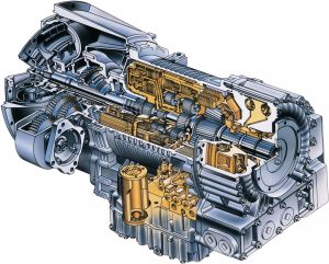
Allison Transmission 1000/2000/3000/4000 Product Families Factory Service & Shop Manual

SAMPLE – Allison Transmission 1000/2000/3000/4000 Product Families Factory Service & Shop Manual


INSTANT DOWNLOAD


Complete workshop & service manual with bonus troubleshooting manuals for Allison Transmission 1000/2000/3000/4000 Product Families. It’s the same service manual used by dealers that guaranteed to be fully functional and intact without any missing page.

This Allison Transmission 1000/2000/3000/4000 Product Families service & repair manual (including maintenance, overhaul, disassembling & assembling, adjustment, tune-up, operation, inspecting, diagnostic & troubleshooting…) is divided into different sections. Each section covers a specific component or system with detailed illustrations. A table of contents is placed at the beginning of each section. Pages are easily found by category, and each page is expandable for great detail. The printer-ready PDF documents work like a charm on all kinds of devices.

FILELIST:
“GN4008EN.pdf”
Allison Transmission Allison 4th Generation Controls (1000 Product Family, 2000 Product Family) In-Chassis Maintenance; 2007 JANUARY; GN4008EN

“JA3664EN.pdf”
Allison Transmission VOCATIONAL MODELS In-Chassis Maintenance; 2004 APRIL 01; JA3664EN
1000 EVS, 1000 HS, 1000 MH, 1000 PTS, 1000 RDS, 1000 SP, B 210, 2100 EVS, 2100 HS, 2100 MH, 2100 PTS, 2100 RDS, 2100 SP, B 220, 2200 EVS, 2200 HS, 2200 MH, 2200 PTS, 2200 RDS, 2200 SP, 2500 EVS, 2500 HS, 2500 MH, 2500 PTS, 2500 RDS, 2500 SP
1000 Series, 2000 Series, 2000 MH Series, 2400 Series

“MT4015EN.pdf”
Allison 4th Generation Controls – 3000 Product Family (Except 3700 SP), 4000 Product Family Mechanic’s Tips; 2005 FEBRUARY, Rev. 1 2005 SEPTEMBER; MT4015EN

“OM3349EN.pdf”
Motorhome Series 3000/4000 Operator’s Manual; 2005/09
Allison Transmission VOCATIONAL MODELS Motorhome Series (MH) Transmissions
3000 and 4000 Product Families
WTEC III Controls and Allison 4th Generation Controls
3000 MH, 4000 MH

“OM4118EN.pdf”
Allison Transmission 1000 & 2000 Product Families International Models Operator’s Manual; 2005/09
Includes Allison 4th Generation Controls
1000, 1000 MH, 1000 SP, 2100, 2100 MH, 2100 SP, 2200, 2200 MH, 2200 SP 2500, 2500 MH, 2500 SP

“SM2148EN.pdf”
3000 Product Family WTEC II & III Controls Service Manual (Rev 2016/01)
Allison Transmission VOCATIONAL MODELS
3000 EVS, 3000 HS, 3000 MH, 3000 PTS, 3000 RDS, 3000 SP, 3000 TRV, MD 3060, MD 3060P, MD 3060R, MD 3060PR, MD 3066, MD 3066P, MD 3066R, MD 3066PR, MD 3070PT, 3200 SP, 3200 TRV, 3500 EVS, 3500 HS, 3500 MH, 3500 PTS, 3500 RDS, 3500 SP, MD 3560, MD 3560P, MD 3560R, MD 3560PR, 3700 SP, B 300, B 300P, B 300R, B 300PR, B 400, B 400P, B 400R, B 400PR, T 250, T 255, T 260, T 265, T 270, T 280, T 310, T 325, T 350, T 375

“SM2457EN.pdf”
4000 Product Family On-Highway Transmissions WTEC II & III Controls Service Manual (Rev 2007/03)
Allison Transmission WTEC II AND WTEC III CONTROLS VOCATIONAL MODELS
4000 EVS, 4000 HS, 4000 MH, 4000 RDS, 4000 SP, 4000 TRV, HD 4060, HD 4060P, HD 4060R, HD 4060PR, HD 4070, HD 4070P, HD 4070R, HD 4070PR, HD 4076, 4500 EVS, 4500 HS, 4500 SP, 4500 TRV, HD 4560, HD 4560P, HD 4560R, HD 4560PR, 4700 EVS, 4700 RDS, 4700 SP, 4800 EVS, 4800 SP, B 500, B 500P, B 500R, B 500PR, T 425, T 450

“SM3191EN.pdf”
1000 and 2000 Product Families Pre-4th Gen Controls Service Manual (Rev 2004/12)
Allison Transmission VOCATIONAL MODELS SERVICE MANUAL; 2004 DECEMBER
1000 EVS, 1000 HS, 1000 MH, 1000 PTS, 1000 RDS, 1000 SP, 2100 EVS, 2100 HS, 2100 MH, 2100 PTS, 2100 RDS, 2100 SP, 2200 EVS, 2200 HS, 2200 MH, 2200 PTS, 2200 RDS, 2200 SP, 2500 EVS, 2500 HS, 2500 MH, 2500 PTS, 2500 RDS, 2500 SP, B 210, B 220

“SM4006EN.pdf”
1000 and 2000 Product Families Allison 4th Generation Controls Service Manual
Allison Transmission VOCATIONAL MODELS SERVICE MANUAL; 2005 MAY, Rev. 1 2005 SEPTEMBER
1000 EVS, 1000 HS, 1000 MH, 1000 PTS, 1000 RDS, 1000 SP, 2100 EVS, 2100 HS, 2100 MH, 2100 PTS, 2100 RDS, 2100 SP, 2200 EVS, 2200 HS, 2200 MH, 2200 PTS, 2200 RDS, 2200 SP, 2500 EVS, 2500 HS, 2500 MH, 2500 PTS, 2500 RDS, 2500 SP, 2300 HS, 2300 RDS, B 210, B 220

“SM4013EN.pdf”
3000 Product Family Service Manual
ALLISON 4TH GENERATION CONTROLS VOCATIONAL MODELS SERVICE MANUAL; 2005 OCTOBER
3000 EVS, 3000 HS, 3000 MH, 3000 PTS, 3000 RDS, 3000 TRV, 3200 SP, 3200 TRV, 3500 EVS, 3500 RDS, 3500 SP, 3700 SP, B 300, B 400, T 250, T 255, T 260, T 265, T 270, T 280, T 310, T 325, T 350

“SM4014EN.pdf”
4000 Product Family Service Manual
ALLISON 4TH GENERATION CONTROLS VOCATIONAL MODELS SERVICE MANUAL; 2005 OCTOBER
4000 EVS, 4000 HS, 4000 MH, 4000 RDS, 4000 SP, 4000 TRV, 4500 EVS, 4500 HS, 4500 RDS, 4500 SP, 4700 EVS, 4700 RDS, 4700 SP, 4800 EVS, 4800 SP, B 500, T 425, T 450, T 525

“TS2470EN.pdf”
WTEC II ELECTRONIC CONTROLS TROUBLESHOOTING MANUAL
1998 MAY; REV. 1 1999 OCTOBER; REV. 2 2004 JULY; REV. 3 2005 DECEMBER
MD/HD/B SERIES TRANSMISSIONS
WTEC II Controls
(Pre-TransID and TID 1)
MD 3060/MD 3066/MD 3560(P)(R)
MD 3070PT
HD 4060/HD 4560(P)(R)
B 300/B 400/ B 500(P)(R)

“TS2712EN.pdf”
ALLISON TRANSMISSION ELECTRONIC CONTROLS TROUBLESHOOTING MANUAL
This document covers the following on- and off-highway transmission models:
MT(B) 648; CLBT 5962 and 6062
HT(B) 741, 746 and 748; DP 8963
HT(B) 755CR and 755DR; CL(B)T 9681
V 731, V 731RH, VR 731, and VR 731RH; CLT 755 and CL(B)T 755

“TS2973EN.pdf”
WTEC III ELECTRONIC CONTROLS TROUBLESHOOTING MANUAL
2005 OCTOBER
REV. 1 OCTOBER 2006
VOCATIONAL MODELS
3000 VOCATIONAL MODELS
3000 HS 3500 RDS B 300(P)(R)
3000 RDS 3500 EVS B 400(P)(R)
3000 EVS T 200
3000 MH T 300
3000 PTS
3000 TRV
3200 SP 3500 SP 3700 SP
3200 TRV
MD 3060 MD 3560 MD 3070PT
MD 3066
4000 VOCATIONAL MODELS
4000 EVS 4500 EVS 4700 EVS 4800 EVS B 500
4000 HS 4500 HS 4700 RDS
4000 MH 4500 RDS
4000 RDS 4500 SP
4000 TRV 4500 TRV
HD 4060 HD 4560 HD 4070 HD 4076 B 500P
HD 4060P HD 4560P HD 4070P B 500R
HD 4060R HD 4560R HD 4070R B 500PR
HD 4060PR HD 4560PR HD 4070PR T 425 T 450

“TS3192EN.pdf”
ALLISON 1000/2000/2400 PRODUCT FAMILIES ELECTRONIC CONTROLS TROUBLESHOOTING MANUAL
2003 APRIL
REV. 1 2004 MAY

“TS3353EN.pdf”
5000, 6000, 8000, 9000 Series Transmissions
COMMERCIAL ELECTRONIC CONTROLS 2 (CEC2) TROUBLESHOOTING MANUAL
2005 DECEMBER
M 5610A M 5610AR
S 5610H S 5610MR S 5610M
M 6610A M 6610AR
S 6610H S 6610HR S6610M S 6610MR
M 8610A M 8610AR
S 8610H S 8610HR S 8610M S 8610MR
M 9610A M 9610AR
S 9610A S 9610AR S 9610M S 9610MR
S 9805M S 9805MR
S 9810A S 9810AR S 9810H S 9810HR
S 9810M S 9810MR

“TS3977EN.pdf”
2008 FEBRUARY
REV. 2 2008 SEPTEMBER
ALLISON 4th GENERATION CONTROLS
1000 AND 2000 PRODUCT FAMILIES TROUBLESHOOTING MANUAL

“TS3977FR.pdf”
GROUPES DE PRODUITS 1000 ET 2000 MANUEL DE DÉPANNAGE — COMMANDES ALLISON 4ème GÉNÉRATION
JANVIER 2006

“TS3989FR.pdf”
FÉVRIER 2005
GROUPES DE PRODUITS 3000 ET 4000 MANUEL DE DÉPANNAGE—COMMANDES ALLISON 4ème GÉNÉRATION
MODÈLES SPÉCIALISÉS Manuel de dépannage FÉVRIER 2005
MODÈLES 3000 SPÉCIALISÉS
3000 HS 3500 RDS B 300(P)(R)
3000 RDS 3500 EVS B 400(P)(R)
3000 EVS T 200
3000 MH T 300
3000 PTS
3000 TRV
3200 SP 3500 SP 3700 SP 3200 TRV
MODÈLES 4000 SPÉCIALISÉS
4000 EVS 4500 EVS 4700 EVS 4800 EVS B 500
4000 HS 4500 HS 4700 RDS B 500P
4000 MH 4500 RDS B 500R
4000 RDS 4500 SP B 500PR
4000 TRV 4500 TRV T 425 T 450

“CD2456EN“
4000 Product Family Series Transmissions Parts Catalog CD

EXCERPT:
MODULE REBUILD
b. Ground Sleeve Inspection
NOTE:
• The ground sleeve bushing and bearing are re- placed with the ground sleeve installed in the front support.
— Replace the needle bearing if the bearing is damaged.
— Replace the bushing if the bushing is damaged or the ID specification is not met.
• The only time the ground sleeve is pressed from the front support is to replace the ground sleeve.
— The new ground sleeve comes with a pre-installed bushing.
— Replace the ground sleeve if the ground sleeve splines or seal-ring bore specification is not met.
• The bearing must be removed to replace the ground sleeve. If the ground sleeve and the bear- ing both need replacing, replace the ground sleeve first.
• Replace the ground sleeve if it does not meet specifications.
1. Inspect the splines of ground sleeve (1) for damage and wear. No visible wear is allowed.
2. Measure the ID of ground sleeve (2) at the turbine shaft sealring bore (Dimension A). Maximum ID is 45.450 mm (1.7894 inch).
3. Measure the ID of ground sleeve bushing (1) (Dimension B). Maximum ID is 33.820 mm (1.3315 inch).


INSTANT DOWNLOAD


Posted on

Alfa Romeo Giulietta 2010-2015 Workshop Repair & Service Manual

Alfa Romeo Giulietta 2010-2015 (NL)


Download Link

INSTANT DOWNLOAD (add to cart)

Complete digital official shop manual in Dutch contains service, maintenance, and troubleshooting information for the 2010-2015 Alfa Romeo Giulietta. Diagnostic and repair procedures are covered in great detail to repair, maintain, rebuild, refurbish or restore your vehicle like a professional mechanic in local service/repair workshop. This cost-effective quality manual is 100% complete and intact as should be without any missing pages. It is the same factory shop manual used by dealers that guaranteed to be fully functional to save your precious time.

This manual for Alfa Romeo Giulietta 2010-2015 is divided into different sections. Each section covers a specific component or system and, in addition to the standard service procedures, includes disassembling, inspecting, and assembling instructions. A table of contents is placed at the beginning of each section. Pages are easily found by category, and each page is expandable for great detail. It is in the cross-platform PDF document format so that it works like a charm on all kinds of devices. You do not need to be skilled with a computer to use the manual.

PRODUCT DETAILS:
Total Size: 780MB
File Format: PDF (Windows & Mac & Linux)
Language: Dutch (plus some English & Italian documents)
Printable: Yes

EXCERPT (Alfa Romeo A-191 Giulietta(Type 940) Service/Repair Manual):
191 – Giulietta 1.4 Turbo MultiAir REMBLOKKEN ACHTER – VERV. 3310B62
Uitbouwen ( Inbouwen )
In de volgende procedure is het uit-/inbouwen van de remblokken linksachter beschreven; ga voor de remblokken
rechtsachter op dezelfde wijze te werk.
– Zet de auto op een hefbrug.
1. Verwijder de achterremblokken.
1. Verwijder de klemmen van de achterremblokken.
– Monteer de nieuwe klemmen van de achterremblokken.
– Monteer de nieuwe achterremblokken.
– Plaats de achterremklauw in een bankschroef met beschermde bekken.

191 – Giulietta 1.4 Turbo MultiAir LEIDINGEN EN NIPPELS VAN ACHTERRUITENWISSER/-SPROEIER – U.I. 5050C14
– Zet de auto op een hefbrug.
– Zuig de vloeistof uit het ruitensproeierreservoir met een zuigpompje.
1. Draai de bevestigingsbouten (1a) van het voorste deel (1b) van de wielkuipbescherming linksvoor los.
2. Maak het voorste deel (1b) van de wielkuipbescherming linksvoor los en verplaats dit iets naar achteren.
1. Maak de voorste slang (1a) van de achterruitensproeier los van elektropomp (1b).
2. Maak de slang (1a) los uit de borgingen (2a) op het ruitensproeierreservoir.
– Laat de auto zakken.
1. Maak aan de linker zijde van de accu het koppelstuk (1a) los en verwijder de voorste slang (1b) van de
achterruitensproeier.
– Zie voor het losmaken van het achterste deel van de slang:
– Controleer de voorste slang van de achterruitensproeier op beschadigingen.
– Plaats de slang.
– Sluit aan de linkerzijde van de accu het koppelstuk van de slang aan.
– Zet de auto omhoog.
– Sluit de slang aan op de elektropomp.
– Bevestig de slang in de borgingen op het reservoir.
– Plaats de wielkuipbescherming.
– Draai de bevestigingsbouten van de wielkuipbescherming vast.
– Vul het ruitensproeierreservoir.
– Verwijder de auto van de hefbrug.

191 – Giulietta 1.6 JTDM HITTESCHILD VAN UITLAATPIJP OP BRANDSTOFTANK – U.I. 1076A51
– Zet de auto op een hefbrug.
1. Draai de bevestigingsbout (1a) van de beugel voor het ophangrubber van de voorste uitlaatdemper (1b) los.
1. Druk de borgveren van het hitteschild samen en verwijder ze.
1. Draai de getande veerklem (1a) los en verwijder het hitteschild voor de uitlaatpijp op de brandstoftank (1b).
Inbouwen ( Uitbouwen )
– Plaats het hitteschild en bevestig het m.b.v. de borgklemmen.
– Draai de bevestigingsbout van de beugel voor het ophangrubber van de voorste uitlaatdemper met aanhaalmoment vast.
– Verwijder de auto van de hefbrug.

Posted on

Alfa Romeo Milano/Giulietta/Spider/Guilia/Alfetta/AR 1963-1995 Workshop Repair & Service Manual

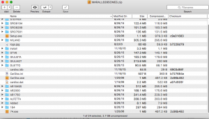
MARALL6395OMES.zip
Price: $19.99 USD

Complete digital official shop manual contains service, maintenance, and troubleshooting information for the 1963-1995 Alfa Romeo 164, Alfetta, Alfetta GTV 6, AR 1750, AR 2000, Guilia GT, Giulietta 54-64, Milano, 75, Spider, Spider Duetto. Diagnostic and repair procedures are covered in great detail to repair, maintain, rebuild, refurbish or restore your vehicle like a professional mechanic in local service/repair workshop. This cost-effective quality manual is 100% complete and intact as should be without any missing pages. It is the same factory shop manual used by dealers that guaranteed to be fully functional to save your precious time.

This manual is divided into different sections. Each section covers a specific component or system and, in addition to the standard service procedures, includes disassembling, inspecting, and assembling instructions. A table of contents is placed at the beginning of each section. Pages are easily found by category, and each page is expandable for great detail.

MAKE: Alfa Romeo
MODEL: ’91-’95 164, ’75-’79 Alfetta, ’81-’86 Alfetta GTV 6, ’69-’71 AR 1750, ’72-’74 AR 2000, ’63-’68 Guilia GT, Giulietta 54-64, ’86-’93 Milano/75, ’75-’81 Spider, ’82-’89 Spider, ’91-’94 Spider, Spider Duetto
YEAR: 1963, 1964, 1965, 1966, 1967, 1968, 1969, 1970, 1971, 1972, 1973, 1974, 1975, 1976, 1977, 1978, 1979, 1980, 1981, 1982, 1983, 1984, 1985, 1986, 1987, 1988, 1989, 1990, 1991, 1992, 1993, 1994, 1995
SIZE: 2.7 GB

EXCERPT:
ALFA ROMEO
3.0L V6
MANUFACTURER’S SUGGESTED SCHEDULED MAINTENANCE
The manufacturer recommends the belt be replaced every 50,000 miles.
REMOVAL & INSTALLATION
TIMING BELT
Removal
1. Disconnect negative battery cable. Raise and support vehicle. Remove right front wheel. Remove right front inner fenders. Disconnect throttle opening switch electrical connector. Remove throttle body cover.
2. Remove water pump, air conditioning, and power steering drive belts. Remove hydraulic belt tensioner.
Disconnect crankshaft position sensor connector, and remove sensor. Disconnect constant idle speed actuator electrical connector. Disconnect oil vapor separator hoses.
3. Disconnect accelerator cable. On models equipped with automatic transmission, disconnect kickdown cable. On S models, disconnect engine throttle sensor electrical connector. On all models, disconnect fuel vapor and cruise control hoses.
4. Disconnect fuel pressure regulator and power brake unit vacuum hoses. Disconnect ground strap from air intake box. Remove air intake box attaching screws and clamps, and remove air intake box.
5. Disconnect spark plug wires for cylinders No. 1, 2 and 3. Remove intake ducts and gaskets. Remove right valve cover and gasket. Disconnect spark plug wires for cylinders No. 4, 5 and 6. Remove left side valve cover and gasket.
6. Partially drain cooling system. Disconnect coolant hose from thermostat unit. Disconnect return hose from water pump. Disconnect coolant temperature switch and sensor electrical connectors. If equipped, disconnect oil cooling tubes from heat exchanger.
7. Remove timing belt covers. Remove spark plugs Rotate crankshaft so No. 1 cylinder is at TDC of compression stroke. Flywheel and transmission housing timing marks should align. See Fig. 1. Camshaft sprocket timing marks should align with bearing cap marks. See Fig. 2.
8. Lift belt tensioner arm from timing belt. Insert Holding Tool (1.820.053.00) or equivalent into hole on arm to lock in position. Loosen hydraulic belt tensioner retaining nuts. Push tensioner downward to limit of travel, and tighten upper retaining nut. Remove timing belt.
Fig. 1: Identifying Flywheel Timing Marks
Fig. 2: Identifying Camshaft Timing Marks
Installation
1. Position Adapter (1.825.007.000), or equivalent, and a dial indicator into No. 1 cylinder spark plug hole. See Fig. 2. Ensure camshaft and crankshaft timing marks align.
2. Install timing belt over crankshaft sprocket, left camshaft sprocket, right camshaft sprocket, and oil pump sprocket hydraulic belt tensioner pulley. See Fig. 3. Maintain tension on timing belt during installation.

Posted on

Alfa Romeo 4C 2013-2016 Workshop Repair & Service Manual


Download Link

INSTANT DOWNLOAD (add to cart)

SAMPLE NEW 4C MODEL

Complete digital official shop manual contains service, maintenance, and troubleshooting information for the Alfa Romeo 4C 2013-2016. Diagnostic and repair procedures are covered in great detail to repair, maintain, rebuild, refurbish or restore your vehicle like a professional mechanic in local service/repair workshop. This cost-effective quality manual is 100% complete and intact as should be without any missing pages. It is the same factory shop manual used by dealers that guaranteed to be fully functional to save your precious time.

This manual for Alfa Romeo 4C 2013-2016 is divided into different sections. Each section covers a specific component or system and, in addition to the standard service procedures, includes disassembling, inspecting, and assembling instructions. A table of contents is placed at the beginning of each section. Pages are easily found by category, and each page is expandable for great detail. It is in the cross-platform PDF document format so that it works like a charm on all kinds of devices. You do not need to be skilled with a computer to use the manual.

EXCERPT:
The Fiat Powertrain Technologies Alfa TCT is a three-shaft transmission capable of transmitting a maximum torque of 350 Nm. It uses innovative technology that allows driving comfort to be combined with an automatic transmission, with lower running costs than for manual gearboxes.
The Alfa TCT transmission is made by combining two aluminium alloy half-casings. It can be installed in front wheel drive, transverse engine layout arrangements. The Alfa TCT has a typical three-shaft layout for additional compactness. A particularity is that the main shaft actually consists of two mutually coaxial driveshafts. Two dry clutches operated by two separate hydraulic actuators are used to transmit torque to the main shaft:
a traditional one located under the transmission casing (traditional) to manage the even gear clutch;
the second one located on the transmission casing to manage the odd gear clutch.
Gears are engaged and the clutches are managed by an electro-hydraulic robot, controlled in turn by a specific transmission control unit (NCR). The electro-hydraulic robot is positioned directly on the transmission casing.

Posted on

Alexander Dennis Dart SLF, Enviro 400 Workshop Repair & Service Manual

SAMPLE Alexander Dennis Enviro 400


INSTANT DOWNLOAD


Complete digital official shop manual contains service, maintenance, and troubleshooting information for the Alexander Dennis Dart SLF (Euro3/Euro4), Enviro 400 (EURO3/EURO4&4+) Bus. Diagnostic and repair procedures are covered in great detail to repair, maintain, rebuild, refurbish or restore your vehicle like a professional mechanic in local service/repair workshop. This cost-effective quality manual is 100% complete and intact as should be without any missing pages. It is the same factory shop manual used by dealers that guaranteed to be fully functional to save your precious time.

This manual for Alexander Dennis Dart SLF (Euro3/Euro4), Enviro 400 (EURO3/EURO4&4+) Bus is divided into different sections. Each section covers a specific component or system and, in addition to the standard service procedures, includes disassembling, inspecting, and assembling instructions. A table of contents is placed at the beginning of each section. Pages are easily found by category, and each page is expandable for great detail. It is in the cross-platform PDF document format so that it works like a charm on all kinds of devices. You do not need to be skilled with a computer to use the manual.

MAKE: Alexander Dennis
MODEL: Dart SLF (Euro3/Euro4), Enviro 400 (EURO3/EURO4&4+)
FORMAT: PDF

2197:
Dart SLF Euro 3 – 4 Cylinder Parts Manual
Date: Nov 2001 (05/06); 280 pages

2209:
Dart SLF Euro 3 Service Manual
Date: Nov 2001 (01/06); 378 pages

2225:
Dart 4 & 6 cylinder/ Pointer Operation Guide
Date: September 2003 (03/04); 72 pages

2266:
Dart 4 & 6 cylinder/ Pointer Operation Guide
Date: October 2003 (08/05); 72 pages

2291:
Enviro 400 (EURO 4&4+) 4 & 6 cylinder Service Manual
Date: July 2006 (03/08); 474 pages

2292:
Enviro 400 (EURO 3) Service Manual
Date: December 2005 (03/06); 450 pages

2297:
Enviro 400 (EURO 4&4+) Service Manual
Date: March 2006 (10/07); 466 pages

2300:
Dart E4 Pointer Handbook

2301:
Dart Euro 4 Parts Manual
Covering EURO 4 CHASSIS 4-CYLINDER MODELS: SFD1HFCR56GW1, SFD1HFCR56GW9, SFD2HFCR56GW9
Publication Number: 2301 Date: October 2006

2302:
Dart SLF Euro 4 – 4 Cylinder Models Service Manual
Date: September 2006; 294 pages

EXCERPT:
Air Cleaner – Amended:

Description
The air cleaner is fitted on the nearside of the vehicle. The cleaner encloses a pleated filter element which is treated to combat premature blockage by exhaust carbon.
A remote restriction indicator is connected to the outlet to indicate clogging.

Maintenance
Access is obtained through the rear engine door. The element should be changed if the restriction indicator (fitted adjacent to the rear EDC) shows red. It is not recommended that treated elements should be washed as this removes the active chemical. In a case of necessity the element can be cleaned by blowing through with air at a max 100 p.s.i. (7 bar) in the reverse direction. To remove the element, undo the centre hand nut on the cleaner casing lid. Pull out the element and wipe out the inside of the casing with a damp cloth. Check that the gaskets are in good condition and that the casing and lid are undamaged. Fit the new element, position the lid and tighten the hand nut. If necessary reset the restriction indicator by pressing down on the top.

Vehicle checks
After reassembly but before restarting engine, the following system checks must be carried out.
a. Check all cleaner to engine pipe work for defects to ensure good and leak free condition.
b. Check that all rubber hose connections are tight and leak free. Renew any worn or damaged parts.
c. Check that the cleaner mounting fixtures are secure.

Restriction Indicator
The restriction indicator gives a warning that the air cleaner filter is too clogged for further service. The indicator is operated by the depression between the air cleaner and the engine, and at a preset figure, the red warning indicator will remain locked up in a visible position after the engine has stopped running.
When the red indicator band appears, the air cleaner element must be removed and renewed. After the element has been renewed, reset the indicator by pushing on the diaphragm at the top of the instrument. Blank off the connection if the indicator is not fitted.


INSTANT DOWNLOAD