Posted on

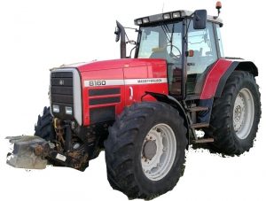
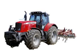
AGCO / Massey Ferguson 8200 Series Tractors Factory Service & Shop Manual


ACRO 8200-Series


INSTANT DOWNLOAD


Complete workshop & service manual with electrical wiring diagrams for AGCO / Massey Ferguson 8200 Series Tractors (8210, 8220, 8220 Heavy Duty, 8220 Xtra, 8240, 8240 Xtra, 8245, 8245 Heavy Duty, 8250, 8250 Xtra, 8260, 8260 Xtra, 8270, 8270 Xtra, 8280, 8280 Xtra). It’s the same service manual used by dealers that guaranteed to be fully functional and intact without any missing page.

This AGCO / Massey Ferguson 8200 Series Tractors service & repair manual (including maintenance, overhaul, disassembling & assembling, adjustment, tune-up, operation, inspecting, diagnostic & troubleshooting…) is divided into different sections. Each section covers a specific component or system with detailed illustrations. A table of contents is placed at the beginning of each section. Pages are easily found by category, and each page is expandable for great detail. The printer-ready PDF documents work like a charm on all kinds of devices.

Workshop Service Manual for AGCO / Massey Ferguson 8200 Series Tractors (8210, 8220, 8220 Heavy Duty, 8220 Xtra, 8240, 8240 Xtra, 8245, 8245 Heavy Duty, 8250, 8250 Xtra, 8260, 8260 Xtra, 8270, 8270 Xtra, 8280, 8280 Xtra) (Three Point Power, Wintest User Guide)

N° 3378177 M1; May 2001; 2,335 pages

EXCERPT:
8 . FRONT AXLE
8 A01 GENERALITY – CARRARO FRONT AXLE
8 B01 DANA FINAL DRIVE UNITS
8 B02 ZF FINAL DRIVE UNITS
8 B03 CARRARO FINAL DRIVE UNITS
8 C01 DANA DIFFERENTIAL
8 C02 ZF DIFFERENTIAL
8 C03 CARRARO DIFFERENTIAL
8 D01 2 WD FRONT AXLE
8 E01 STEERING COLUMN
8 F01 BEARINGS AND TRANSMISSION SHAFTS (DANA FRONT AXLE)
8 F02 BEARINGS AND TRANSMISSION SHAFTS (ZF FRONT AXLE)
8 F03 BEARINGS AND TRANSMISSION SHAFTS (CARRARO FRONT AXLE)
8 G01 4WD CLUTCH
8 G02 CARRARO SUSPENSION
8 I01 CARRARO TROUBLESHOOTING

Front axle – Generality
The axle described in this manual, designed and manufactured following the customer’s requests, consists of a beam casing, housing the differential in the middle and a wheel hub unit at each end.
The differential, type “Limited Slip”, is supported by two bearings mounted on a suitable structure allowing the bevel gear set to be adjusted.
The ring bevel gear is adjusted by means of two ring nuts located opposite each other.
The position of the bevel pinion, supported by two bearings, is adjusted by inserting adjusting shims.
The wheel hubs containing the epicyclic reduction gears are supported by two tapered roller bearings and are powered by a hydraulically-operated steering unit.
The axle is equipped with hydropneumatic shock-absorbing suspension system (Carraro patent), electronically controlled, ensuring the constant contact of the tyres with the ground in any operating conditions.


INSTANT DOWNLOAD


Posted on

AGCO/Massey-Ferguson Tractor Series 8100 Factory Service & Shop Manual


Pages from AGCO-Massey-Ferguson Tractor Series 8100 (Model MF 8110-8120-8130-8140-8150-8160) Workshop Service Manual

MMF8100OPES.zip
Price: $29.99 USD

Complete workshop & service manual with electrical wiring diagrams for AGCO/Massey-Ferguson Tractor Series 8100 (Model MF 8110, 8120, 8130, 8140, 8150, 8160). It’s the same service manual used by dealers that guaranteed to be fully functional and intact without any missing page.

This AGCO/Massey-Ferguson Tractor Series 8100 (Model MF 8110/8120/8130/8140/8150/8160) service & repair manual (including maintenance, overhaul, disassembling & assembling, adjustment, tune-up, operation, inspecting, diagnostic & troubleshooting…) is divided into different sections. Each section covers a specific component or system with detailed illustrations. A table of contents is placed at the beginning of each section. Pages are easily found by category, and each page is expandable for great detail. The printer-ready PDF documents work like a charm on all kinds of devices.

AGCO/Massey-Ferguson Tractor Series 8100 (Model MF 8110/8120/8130/8140/8150/8160) Workshop Service Manual.pdf

EXCERPT:
TABLE OF CONTENTS
WORKSHOP SERVICE MANUAL
1 Introduction – Specifications
2 Splitting the tractor
3 Engine and equipment
4 Clutch
5 Gearbox
6 Rear axle
7 Power Take Off
8 Front axle 2 and 4WD
9 Hydraulics
10 Electrical equipment
11 Electronics
12 Cab and Equipment

Clutch 4A01.7
D. Removing, refitting, and shimming the clutch
Removal
24.Split the tractor between the engine and the gearbox (see section 2801 ).
25. Drain the oil from the gearbox and rear axle.
26. If the tractor is fitted with the chassis reinforce- ments, remove the right-hand side.
27. Remove the tube (17).
28. Remove the cover plate (1 0).
Repeat procedure 12.
29. Remove the tube (20).
30. Remove the union (72) and tubes (70) and (65).

Posted on

AGCO/Massey-Ferguson Tractor Series 6400 Factory Service & Shop Manual


Pages from AGCO-Massey-Ferguson Tractor Series 6400 (Model MF 6445-6455-6460-6465-6470-6475-6480-6485-6490-6495-6497-6499) Workshop Service Manual

MMF6400OPES.zip
Price: $29.99 USD

Complete workshop & service manual with electrical wiring diagrams for AGCO/Massey-Ferguson Tractor Series 6400 (Model MF 6445/6455/6460/6465/6470/6475/6480/6485/6490/6495/6497/6499). It’s the same service manual used by dealers that guaranteed to be fully functional and intact without any missing page.

This AGCO/Massey-Ferguson Tractor Series 6400 (Model MF 6445, 6455, 6460, 6465, 6470, 6475, 6480, 6485, 6490, 6495, 6497, 6499) service & repair manual (including maintenance, overhaul, disassembling & assembling, adjustment, tune-up, operation, inspecting, diagnostic & troubleshooting…) is divided into different sections. Each section covers a specific component or system with detailed illustrations. A table of contents is placed at the beginning of each section. Pages are easily found by category, and each page is expandable for great detail. The printer-ready PDF documents work like a charm on all kinds of devices.

FILELIST:
3378818M1 – AGCO/Massey-Ferguson Tractor 6400 Series Tractors (6497/6499) Operator Instruction Book.pdf
4315415M1 – AGCO/Massey-Ferguson Tractor 6400 Series Tractors (6465/6475/6480) Operator Instruction Book.pdf
AGCO/Massey-Ferguson Tractor Series 6400 (Model MF 6445/6455/6460/6465/6470/6475/6480/6485/6490/6495/6497/6499) Workshop Service Manual.pdf

EXCERPT:
Twin flow load sensing right-hand hydraulic cover
E . Disassembling and reassembling the cover Disassembly
61. Take off the cover (see § C).
62. Place the cover (1) in a vice fitted with plastic jaws. On the outside face (Fig. 1)
63. Mark the locations and types of solenoid valves (7) to (11) and remove them.
64. Mark the location of the switches (6) (19) and remove them.
65. Remove the engine speed sensor.
66. Remove the hydraulic unions and plugs, fitted according to the version.
67. Remove the diagnostics connectors.
Note: On tractors not fitted with trailer braking, if necessary, remove the cover plate (3) (see section 09B03).
68. Take off the high pressure valve (3).
On the inside face (Fig. 2)
69. Take out the screws (31) and remove the inlet manifold (40), seal (24) and pipe (42). Remove seals (41).
Removing the drive pinion
70. Unscrew nut (27). Take off washer (28), pinion (29) and key (30).
71. Take off the pump (see § F).
Reassembly
72. Clean the cover mating faces.
73. Check that no channels (low and high flow rate) are blocked. Check for the presence of the rivets ensuring oil tightness at the end of each channel.
On the inside face (Fig. 2)
74. Refit the pump (see § F).
Refitting the drive pinion
75. Position the key (30). Fit the pinion (29) on the shaft while ensuring that the key is correctly engaged.
Fit washer (28).
76. Smear the nut (27) with Loctite 241 and tighten to a torque of 50 – 60 Nm.
77. Replace the O’rings (41) on the pipe (42).
78. Refit the seal (24), the pipe and the inlet manifold
(40). Refit and moderately tighten the screws (31).

Posted on

Massey-Ferguson Tractor Series 5400 Factory Service & Shop Manual


Pages from AGCO-Massey-Ferguson Tractor Series 5400 (Model MF 5425-5435-5445-5455-5460-5460SA-5465-5470-5470SA-5475SA) Workshop Service Manual

MMF5400OPES.zip
Price: $29.99 USD

Complete workshop & service manual with electrical wiring diagrams for Massey-Ferguson Tractor Series 5400 (Model MF 5425, 5435, 5445, 5455, 5460, 5460SA, 5465, 5470, 5470SA, 5475SA). It’s the same service manual used by dealers that guaranteed to be fully functional and intact without any missing page.

This Massey-Ferguson Tractor Series 5400 (Model MF 5425/5435/5445/5455/5460/5460SA/5465/5470/5470SA/5475SA) service & repair manual (including maintenance, overhaul, disassembling & assembling, adjustment, tune-up, operation, inspecting, diagnostic & troubleshooting…) is divided into different sections. Each section covers a specific component or system with detailed illustrations. A table of contents is placed at the beginning of each section. Pages are easily found by category, and each page is expandable for great detail. The printer-ready PDF documents work like a charm on all kinds of devices.

FILELIST:
AGCO/Massey-Ferguson Tractor Series 5400 (Model MF 5425/5435/5445/5455/5460/5460SA/5465/5470/5470SA/5475SA) Workshop Service Manual.pdf
AGCO/Massey-Ferguson Tractor Series 5400 (Models 5425-5435-5445-5455-5460-5465) Operator Instruction Book.pdf

EXCERPT:
DANA – Differential
E . Removing the differential unit
10. Place the housing (7) in a vice fitted with soft jaws (Fig. 4).
11. Take out the screw (30) and its lock (31) (Fig. 4).
12. Take off the spline nut (32) using the special makeshift wrench (see § Q).
13. Take out the four screws (42).
14. Take off the half-bearings (43) (Fig. 4).
CAUTION: Take care not to release the spring (17) when releasing the differential lock half bearing. The washer (21) that seats the spring should stay in the housing.
15. Remove the differential assembly complete with cones (33) and cups (29) (Fig. 5). Separate the cups from the cones. Remove the shim(s) (22) used to
adjust the backlash.
NOTE: Pair up the bearing cones and cups in they are to be re-used.

Posted on

AGCO/Massey-Ferguson Tractor Series 3000/3100/3600 Factory Service & Shop Manual


Pages from AGCO-Massey-Ferguson Tractor Series 3600 (Model MF 3615-3625-3635-3645) Workshop Service Manual

MMF3000OPES.zip
Price: $29.99 USD

Complete workshop & service manual with electrical wiring diagrams for AGCO/Massey-Ferguson Tractor Series 3000/3100/3600 (3050, 3060, 3065, 3070, 3080, 3095, 3115, 3125, 3120, 3140, 3615, 3625, 3635, 3645). It’s the same service manual used by dealers that guaranteed to be fully functional and intact without any missing page.

This AGCO/Massey-Ferguson Tractor Series 3000/3100/3600 service & repair manual (including maintenance, overhaul, disassembling & assembling, adjustment, tune-up, operation, inspecting, diagnostic & troubleshooting…) is divided into different sections. Each section covers a specific component or system with detailed illustrations. A table of contents is placed at the beginning of each section. Pages are easily found by category, and each page is expandable for great detail. The printer-ready PDF documents work like a charm on all kinds of devices.

FILELIST:
1646915 M1 – AGCO/Massey-Ferguson Tractor Series 3000/3100 (Model MF 3050/3060/3065/3070/3080/3095/3115/3125/3120/3140) Workshop Service Manual.pdf
AGCO/Massey-Ferguson Tractor Series 3600 (Model MF 3615/3625/3635/3645) Workshop Service Manual.pdf

EXCERPT:
Hydraulic Lift
Section 2
Table of Contents
SPECIFICATIONS . . . 248
TECHNICAL FEATURES . . . 248
DIMENSIONAL FEATURES . . 248
CALIBRATION SETTINGS OF CONTROL VALVE . . . 248
DIAGRAM . . . 249
CIRCUIT DIAGRAM OF HYDRAULIC LIFTING DEVICE . . . 250
FUNCTIONING OF CONTROL VALVE . . 251
NEUTRAL PHASE . . 251
DELIVERY PHASE . . 252
DISCHARGE PHASE . . 253
HOW THE INTERNAL LEVERAGE SYSTEM FUNCTIONS . . 254
FUNCTIONING WITH POSITION CONTROL (FIG. PAGE 5.2) . . . 254
FUNCTIONING OF DRAFT CONTROL (FIG. PAGE 5.2 – 5.4) . . 256
COMBINED FUNCTIONING OF POSITION AND DRAFT CONTROL (FIG. PAGE 5.2-5.4) . . . 258
USE OF CONTROL LEVERS . . 259
POSITION CONTROL (LEVER 1) . . 259
DRAFT CONTROL (LEVER 2) . . . 259
COMBINED OPERATION FOR POSITION AND DRAFT CONTROL . . . 259
ADJUSTMENT OF CONTROL VALVE SENSITIVITY . . . 260
FUNCTIONING OF THE SENSITIVITY OF THE CONTROL VALVE . . . 260
ADJUSTMENT OF POSITION CONTROL LEVER . . . 262
ADJUSTMENT OF DRAFT CONTROL LEVER . . 263
CONTROL OF ASSEMBLY OF REACTION SPRING . . . 264
MEASUREMENT CONTROL OF PUSH ROD . . . 265
DIAGNOSTIC . . 266