Posted on

Massey-Ferguson MF 600-Series Factory Service & Shop Manual


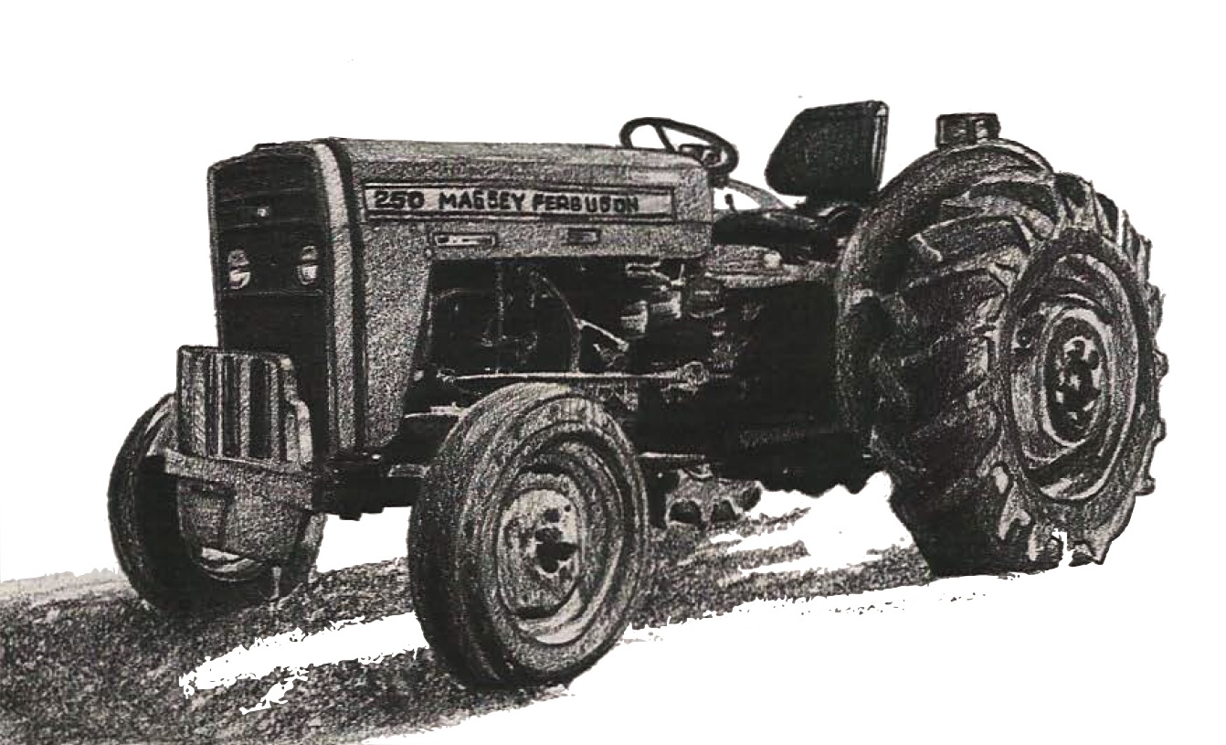
Pages from 1856274 M1 – Massey-Ferguson MF 600 Series Workshop Service Manual

MMF600OPES.zip
Price: $29.99 USD

Complete workshop & service manual with electrical wiring diagrams for Massey-Ferguson MF 600-Series. It’s the same service manual used by dealers that guaranteed to be fully functional and intact without any missing page.

This Massey-Ferguson MF 600-Series service & repair manual (including maintenance, overhaul, disassembling & assembling, adjustment, tune-up, operation, inspecting, diagnostic & troubleshooting…) is divided into different sections. Each section covers a specific component or system with detailed illustrations. A table of contents is placed at the beginning of each section. Pages are easily found by category, and each page is expandable for great detail. The printer-ready PDF documents work like a charm on all kinds of devices.

1856274 M1 – Massey-Ferguson MF 600 Series Workshop Service Manual.pdf

EXCERPT:
CLUTCH RELEASE MECHANISM
GEARBOX TYPES A, B, C, D, E
Special Tools: MS 2700 Rail Trolley
Removal 58-04–11
1. Split the tractor between the engine and the transmission, Part 3A.
2. Remove the two springs.
3. Slide the carrier and release bearing off the input housing.
4. Remove the locking wire and locking peg.
5. Remove the circlip.
6. Remove the shaft.
7. Remove the clutch release fork.
8. Press the release bearing off the carrier.
Refitment
9. Reverse procedures 1 to 8, except:
(a) Lightly lubricate the input shaft splines and the release bearing carrier bore, with special grease Mobilgrease Super.
(b) Ensure that the locking peg locates in the hole in the shaft.

Posted on

Massey-Ferguson Tractors MF230-MF235-MF240-MF245-MF250 Factory Service & Shop Manual


Pages from Massey-Ferguson MF230-MF235-MF240-MF245-MF250 Shop Manual

MMF230MF250OPES.zip
Price: $29.99 USD

Complete workshop & service manual with electrical wiring diagrams for Massey-Ferguson Tractors MF230-MF235-MF240-MF245-MF250. It’s the same service manual used by dealers that guaranteed to be fully functional and intact without any missing page.

This Massey-Ferguson Tractors MF230-MF235-MF240-MF245-MF250 service & repair manual (including maintenance, overhaul, disassembling & assembling, adjustment, tune-up, operation, inspecting, diagnostic & troubleshooting…) is divided into different sections. Each section covers a specific component or system with detailed illustrations. A table of contents is placed at the beginning of each section. Pages are easily found by category, and each page is expandable for great detail. The printer-ready PDF documents work like a charm on all kinds of devices.

Massey-Ferguson Tractors MF230-MF235-MF240-MF245-MF250 Shop Manual.pdf

EXCERPT:
HYDROSTATIC STEERING SYSTEM
This section covers the steering system used on MF2 35 Orchard models arid all MF245 models except Vineyard.
LUBRICATION AND BLEEDING
All Models So Equipped
18. The hydrostatic steering hand pump and steering cylinder assembly are lubricated by the operating fluid.
Massey-Ferguson Pe rmatran III Oil is recommended. The system is self bleeding, but steering should be cycled and reservoir refilled as often as necessary until level stops dropping.
SYSTEM OPERATING PRESSURE AND RELIEF VALUE
All Models So Equipped
19. Normal system relief valve pressure is approximately 8300 kPa (1200 psi) with engine operating at 2000 rpm. Refer to paragraph 7 for testing and adjusting procedures.
STEERING CYLINDER
All Models So Equipped

Posted on

AGCO/Massey-Ferguson MF 185MB Baler & Accumulator Factory Service & Shop Manual


Pages from 1856995M1 – AGCO-Massey-Ferguson MF 185MB Baler & Accumulator Workshop Service Manual

MMF185MOPES.zip
Price: $29.99 USD

Complete workshop & service manual with electrical wiring diagrams for AGCO/Massey-Ferguson MF 185MB Baler & Accumulator. It’s the same service manual used by dealers that guaranteed to be fully functional and intact without any missing page.

This AGCO/Massey-Ferguson MF 185MB Baler & Accumulator service & repair manual (including maintenance, overhaul, disassembling & assembling, adjustment, tune-up, operation, inspecting, diagnostic & troubleshooting…) is divided into different sections. Each section covers a specific component or system with detailed illustrations. A table of contents is placed at the beginning of each section. Pages are easily found by category, and each page is expandable for great detail. The printer-ready PDF documents work like a charm on all kinds of devices.

1856995M1 – AGCO/Massey-Ferguson MF 185MB Baler & Accumulator Workshop Service Manual.pdf

EXCERPT:
Main Roller Bearing Replacement
The main rollers can be removed from the plunger through the side of the baler. Remove only one roller at a time, except when removing the plunger.
Removal
See the safety warnings at the beginning ofthis section and follow the procedures.
1 . Apply the flywheel brake.
2. Disconnect the implement drive line from the tractor.
3. Loosen the cap screws fo~ the shaft retainer.
If you are removinglhe rear roller assembly, loosen the bolt in the pusher plate. Move the shaft retainer out of the groove in the roller shaft and tighten the cap screws.
If you are removing the front roller assembly, loosen the jam nut on the pusher bolt and then loosen the bolt.
Move the shaft retainer out of the groove in the roller shaft and tighten the cap screws.

Posted on

AGCO/Fendt 8370 P, 8400 P Combine Range Factory Service & Shop Manual


Pages from D3151800 M1 – AGCO-Fendt 8370 P, 8400 P Combine Range + Auto Level + Rotary Separator Workshop Service Manual

MFEN8370POPES.zip
Price: $29.99 USD

Complete workshop & service manual with electrical wiring diagrams for AGCO/Fendt 8370 P, 8400 P Combine Range + Auto Level + Rotary Separator. It’s the same service manual used by dealers that guaranteed to be fully functional and intact without any missing page.

This AGCO/Fendt 8370 P, 8400 P Combine Range + Auto Level + Rotary Separator service & repair manual (including maintenance, overhaul, disassembling & assembling, adjustment, tune-up, operation, inspecting, diagnostic & troubleshooting…) is divided into different sections. Each section covers a specific component or system with detailed illustrations. A table of contents is placed at the beginning of each section. Pages are easily found by category, and each page is expandable for great detail. The printer-ready PDF documents work like a charm on all kinds of devices.

FILELIST:
D3151100 M1 – AGCO/Fendt 8370 P, 8400 P + Auto Level + Rotary Separator Operator’s Manual.pdf
D3151800 M1 – AGCO/Fendt 8370 P, 8400 P Combine Range + Auto Level + Rotary Separator Workshop Service Manual.pdf

EXCERPT:
Table of Contents
0 Introduction – Specifications
1 Cutting table
2 Reel
3 Main crop elevator
4 Threshing unit
5 Straw walkers
6 Shaker shoe- Fanning mill
7 Elevators
8 Engine
9 Unloading auger – Grain tank
10 Drive unit
11 Transmissions
12 Undercarriage
13 Cab
14 Hydraulics
15 Machine housing
16 Electrical system (draft)
17 Straw chopper
18 General assembly instructions
19 Miscellaneous data

13.Cab
13.2 Replacing the windscreen
IMPORTANT: The windscreen is glued into the cab and it is advisable to have an expert workshop carry out the replacement. The new windscreen comes with a fitting kit containing the necessary materials, detailed fitting instructions and safety precautions.
1. Dismount the outer roof as described in section 13.4 on page 326.
2. Remove the screws and take off the lamp body on both sides.
3. Remove the screws, including the ones on the back (A), and take the front guard off.
4. Remove the wiper arms.
5. Replace the windscreen in accordance with the fitting instructions provided.

Posted on

AGCO/Fendt 8300/8350 Series Combine Factory Service & Shop Manual


Pages from 63002095 M4 – AGCO-Fendt 8300-8350 Series Combine Workshop Manual


INSTANT DOWNLOAD


Complete workshop & service manual with electrical wiring diagrams for AGCO/Fendt 8300/8350 Series Combine. It’s the same service manual used by dealers that guaranteed to be fully functional and intact without any missing page.

This AGCO/Fendt 8300/8350 Series Combine service & repair manual (including maintenance, overhaul, disassembling & assembling, adjustment, tune-up, operation, inspecting, diagnostic & troubleshooting…) is divided into different sections. Each section covers a specific component or system with detailed illustrations. A table of contents is placed at the beginning of each section. Pages are easily found by category, and each page is expandable for great detail. The printer-ready PDF documents work like a charm on all kinds of devices.

FILELIST:
63002095 M4 – AGCO/Fendt 8300-8350 Series Combine Workshop Manual.pdf
63006340 M4 – AGCO/Fendt 8300-8350-Baureihe RTS Richtzeitliste (DE).pdf
D3150100 M10 – AGCO/Fendt 8300-8350 + Auto Level + Rotary Separator Operator’s Manual.pdf
D3151900 M1 – AGCO/Fendt 8300-8350, 8370P-8400P Series Combine Repair Time Schedule (RTS).pdf

EXCERPT:
Table of Contents
0 Introduction – Specifications
1 Cutting table
2 Reel
3 Main crop elevator
4 Threshing unit
5 Straw walkers
6 Shaker shoe – Fanning mill
7 Elevators
8 Engine
9 Unloading auger – Grain tank
10 Drive unit
11 Transmissions
12 Undercarriage
13 Cab
14 Hydraulics
15 Machine housing
16 Electrical system
17 Straw chopper
18 General assembly instructions
19 Miscellaneous data

12. Undercarriage
12.3 Gearbox – 4 gear ranges
12.3.1 Removal
1 . Dismount the traction wheels and chock up the machine on a secure and reliable support.
2. Drain off gear oil from the coupler housing.
3. Remove the locking bolt and push the bushings (A) towards the brake disc on both sides so that they are clear of the gearbox output shaft IBI.
4. Drain off gear oil from the gearbox.
5. Dismount protection shield.
6. Disconnect the connector for the revolution sensor.
7. Remove the bolts in the shifter shaft.
B. Disconnect the shifter cylinder bracket.
9. Remove the cotter bolt in the handbrake cable.


INSTANT DOWNLOAD