Posted on

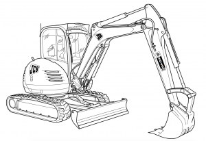
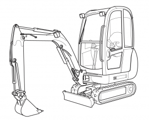
JCB Excavators 8052, 8055, 8060, 8065 Factory Service & Shop Manual


Pages from 9803-9890 – JCB Excavators 8055, 8065 Service Manaual

MJCB80528060OPES.zip
Price: $29.99 USD

Complete workshop & service manual with electrical wiring diagrams for JCB Excavators 8052, 8055, 8060, 8065. It’s the same service manual used by dealers that guaranteed to be fully functional and intact without any missing page.

This JCB Excavators 8052, 8055, 8060, 8065 service & repair manual (including maintenance, overhaul, disassembling & assembling, adjustment, tune-up, operation, inspecting, diagnostic & troubleshooting…) is divided into different sections. Each section covers a specific component or system with detailed illustrations. A table of contents is placed at the beginning of each section. Pages are easily found by category, and each page is expandable for great detail. The printer-ready PDF documents work like a charm on all kinds of devices.

FILELIST:
9803-9290 – JCB Excavators 8052, 8060 Service Manaual.pdf
9803-9890 – JCB Excavators 8055, 8065 Service Manaual.pdf

EXCERPT:
Service Manual
8055, 8065
Section 1 – General Information
Section 2 – Care and Safety
Section 3 – Maintenance
Section A – Attachments
Section B – Body and Framework
Section C – Electrics
Section D – Controls
Section E – Hydraulics
Section F – Gearboxes
Section J – Track and Running Gear
Section K – Engine

Measuring Continuity
1 Make sure there is no power to the part of the circuit you are checking for continuity.
2 Connect one probe to one end of the component or wire to be checked and the other probe to the other end. It does not matter which way round the two probes are placed.
3 Select the correct range on the multimeter.
a On the FLUKE 85.
Turn the switch to position 1-C and check that the beeper symbol appears at the left hand side of the display window. If the F sign is on instead, press the button labelled 1-F in the meter drawing.
If there is continuity in the circuit, the beeper will sound. If there is no continuity (open circuit), the beeper will not sound.
b On the AV0 2003.
Move the right hand slider switch to position 2-B, and the left hand slider switch to position 2-C.
If there is continuity (i.e. very low resistance) between two points the buzzer will sound.
c On an analogue meter.
Turn the dial to the lowest Ohms (Ω) range.
If there is continuity (i.e. very low resistance) between two points the needle will move across fully (or almost fully) to the right hand side of the scale.
Measuring Frequency
The AVO 2003 and the analogue meter are not capable of measuring frequency, therefore a Fluke 85 digital multimeter must be used.
1 Insert the black plug into the COM socket on the meter and attach the probe to the nearest suitable earth point on the chassis, for example, the battery negative terminal.
2 Insert the red probe into socket 1-J.
3 Turn the selector switch to position 1-A and depress 1-G repeatedly until 1-F is highlighted on the top row of the display.
4 Press button 1-H once.
5 Touch or connect the red probe to the frequency source to be measured. Press and hold button if an average reading is required.

Posted on

JCB Excavators 8040, 8045, 8050, 8055 Factory Service & Shop Manual


Pages from 9813-1850 – JCB 8040, 8045, 8050, 8055 Service Manual

MJCB80408055OPES.zip
Price: $29.99 USD

Complete workshop & service manual with electrical wiring diagrams for JCB Excavators JCB Excavators 8040ZTS, 8045ZTS, 8050ZTS, 8050RTS, 8055ZTS, 8055RTS. It’s the same service manual used by dealers that guaranteed to be fully functional and intact without any missing page.

This JCB Excavators 8040ZTS, 8045ZTS, 8050ZTS, 8050RTS, 8055ZTS, 8055RTS service & repair manual (including maintenance, overhaul, disassembling & assembling, adjustment, tune-up, operation, inspecting, diagnostic & troubleshooting…) is divided into different sections. Each section covers a specific component or system with detailed illustrations. A table of contents is placed at the beginning of each section. Pages are easily found by category, and each page is expandable for great detail. The printer-ready PDF documents work like a charm on all kinds of devices.

FILELIST:
9813-1850 – JCB Excavators 8040, 8045, 8050, 8055 Service Manual.pdf
9803-9360 – JCB Excavators 8040ZTS, 8045ZTS, 8050RTS, 8050ZTS Service Manual.pdf

EXCERPT:
8040, 8045, 8050, 8055 Service Manual
Section 1 – General Information
Section 2 – Care and Safety
Section 3 – Maintenance
Section A – Attachments
Section B – Body and Framework
Section C – Electrics
Section D – Controls
Section E – Hydraulics
Section F – Gearboxes
Section J – Track and Running Gear
Section K – Engine

JCB 8040ZTS from serial number 1056000.
JCB 8045ZTS from serial number 1057000.
JCB 8050ZTS from serial number 1741500.
JCB 8050RTS from serial number 1741500.
JCB 8055ZTS from serial number 2060250.
JCB 8055RTS from serial number 2060250.

Replacing the Control Valves
1 Remove the valve(s) as shown below.
2 Measure dimensions X and Y and record them.
Fig 15.
3 Examine the sealing surface Z for damage.
4 Fit new `O’-rings when refitting the control valve(s).
5 Set up the pump before use, see Pump Setup Procedure.

Posted on

JCB Excavators 8025ZTS, 8026CTS, 8027Z, JS30, 8029CTS, 8030ZTS, 8032Z, 8035ZTS Factory Service & Shop Manual


Pages from 9803-9410 – JCB 8025ZTS, 8026CTS, JS30, 8029CTS, 8030ZTS, 8035ZTS Service Manual


INSTANT DOWNLOAD


Complete workshop & service manual with electrical wiring diagrams for JCB Excavators 8025ZTS, 8026CTS, 8027Z, JS30, 8029CTS, 8030ZTS, 8032Z, 8035ZTS. It’s the same service manual used by dealers that guaranteed to be fully functional and intact without any missing page.

This JCB Excavators 8025ZTS, 8026CTS, 8027Z, JS30, 8029CTS, 8030ZTS, 8032Z, 8035ZTS service & repair manual (including maintenance, overhaul, disassembling & assembling, adjustment, tune-up, operation, inspecting, diagnostic & troubleshooting…) is divided into different sections. Each section covers a specific component or system with detailed illustrations. A table of contents is placed at the beginning of each section. Pages are easily found by category, and each page is expandable for great detail. The printer-ready PDF documents work like a charm on all kinds of devices.

FILELIST:
9803-9300 – JCB Excavators 8027Z, 8032Z Service Manual.pdf
9803-9410 – JCB Excavators 8025ZTS, 8026CTS, JS30, 8029CTS, 8030ZTS, 8035ZTS Service Manual.pdf

EXCERPT:
Service Manual – 8025ZTS, 8026CTS, JS30, 8029CTS, 8030ZTS, 8035ZTS
Section 1 – General Information
Section 2 – Care and Safety
Section 3 – Maintenance
Section A – Attachments
Section B – Body and Framework
Section C – Electrics
Section D – Controls
Section E – Hydraulics
Section F – Gearboxes
Section J – Track and Running Gear
Section K – Engine

Servo Hand Controllers
Introduction
This section deals with the Remote Control Valve which provides pilot pressure for the hydraulic control valve and electrical switching to flow-control solenoids.
The remote control valve is a pressure reduction valve used to control the pilot pressure operated system. Four pressure reduction valves used to control the pilot pressure are located in the main housing. Direction of the output pilot pressure is controlled by selective movement of the control lever. The valves and control levers are mounted in the arm rests on both sides of the operator’s seat.


INSTANT DOWNLOAD


Posted on

JCB Excavators 8013, 8014, 8015, 8016, 8017, 8018, 8020, 801 gravemaster Factory Service & Shop Manual


Pages from 9803-9600 – JCB Excavators 8020 Service Manual

MJCB801XOPES.zip
Price: $29.99 USD

Complete workshop & service manual with electrical wiring diagrams for JCB Excavators 8013, 8014, 8015, 8016, 8017, 8018, 8020, 801 gravemaster. It’s the same service manual used by dealers that guaranteed to be fully functional and intact without any missing page.

This JCB Excavators 8013, 8014, 8015, 8016, 8017, 8018, 8020, 801 gravemaster service & repair manual (including maintenance, overhaul, disassembling & assembling, adjustment, tune-up, operation, inspecting, diagnostic & troubleshooting…) is divided into different sections. Each section covers a specific component or system with detailed illustrations. A table of contents is placed at the beginning of each section. Pages are easily found by category, and each page is expandable for great detail. The printer-ready PDF documents work like a charm on all kinds of devices.

FILELIST:
9803-3105 – JCB Excavators 8013, 8015, 8017, 8018, 801 gravemaster Service Manual.pdf
9803-9350 – JCB Excavators 8014, 8016, 8018, 8020 Service Manual.pdf
9803-9600 – JCB Excavators 8020 Service Manual.pdf

EXCERPT:
General Information
Section 1 – General Information
Section 2 – Care and Safety
Section 3 – Maintenance
Section A – Attachments
Section B – Body and Framework
Section C – Electrics
Section D – Controls
Section E – Hydraulics
Section F – Gearboxes
Section J – Track and Running Gear
Section K – Engine

Removal and Replacement
Removal
1 Park the machine on firm level ground. Lower the excavator and dozer to the ground.
2 Stop the engine and remove the starter key.
3 Vent the hydraulic system.
Fig 3.
4 Remove arm rest plug A and undo screw C.
5 Remove armrest B.
6 Remove clamping ring D.
Fig 4.
7 Undo screws E and raise the hand controller F from the housing.

Posted on

JCB Fastrac 7000 Series (7170, 7200, 7230 P-TRONIC) Factory Service & Shop Manual


Pages from 9803-8060 – JCB Fastrac 7000 Series (7170, 7200, 7230 P-TRONIC) Service Manual

MJCB7000FTOPES.zip
Price: $29.99 USD

Complete workshop & service manual with electrical wiring diagrams for JCB Fastrac 7000 Series (7170, 7200, 7230 P-TRONIC). It’s the same service manual used by dealers that guaranteed to be fully functional and intact without any missing page.

This JCB Fastrac 7000 Series (7170, 7200, 7230 P-TRONIC) service & repair manual (including maintenance, overhaul, disassembling & assembling, adjustment, tune-up, operation, inspecting, diagnostic & troubleshooting…) is divided into different sections. Each section covers a specific component or system with detailed illustrations. A table of contents is placed at the beginning of each section. Pages are easily found by category, and each page is expandable for great detail. The printer-ready PDF documents work like a charm on all kinds of devices.

9803-8060 – JCB Fastrac 7000 Series (7170, 7200, 7230 P-TRONIC) Service Manual.pdf

EXCERPT:
Service Manual
JCB 7000 Series Fastrac
Section 1 – General Information
Section 2 – Care and Safety
Section 3 – Maintenance
Section A – Optional Equipment
Section B – Body and Framework
Section C – Electrics
Section E – Hydraulics
Section F – Transmission
Section G – Brakes
Section H – Steering
Section S – Suspension
Section T – Engine

Dismantling and Assembly
The numerical sequence shown on the illustration is intended as a guide to dismantling K Fig 33. ( T E-25).
Before removing and dismantling the pump, check the flow and pressure for each section of the pump (see Section H, Steering and Section S, Suspension – Technical Data).
If the values are low, renewal of components such as gears, bearings and housings will not effect a permanent cure. If the pump output is satisfactory but there is external leakage, dismantle the pump for re-sealing only.
Note: If the steering flow rate is low, make sure that there is no dirt in the end cover 12 and that the spool 10 moves freely. The size of washer 9 controls the steering flow rate (see Technical Information Bulletin 10/183).
For assembly the sequence should be reversed.
When Dismantling