Posted on

JCB Hydraulic Excavators JS130W, JS145W, JS150W, JS160W, JS175W Factory Service & Shop Manual


MJCBJS130W175WOPES.zip
Price: $29.99 USD

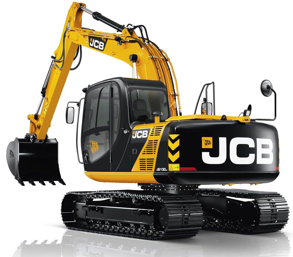
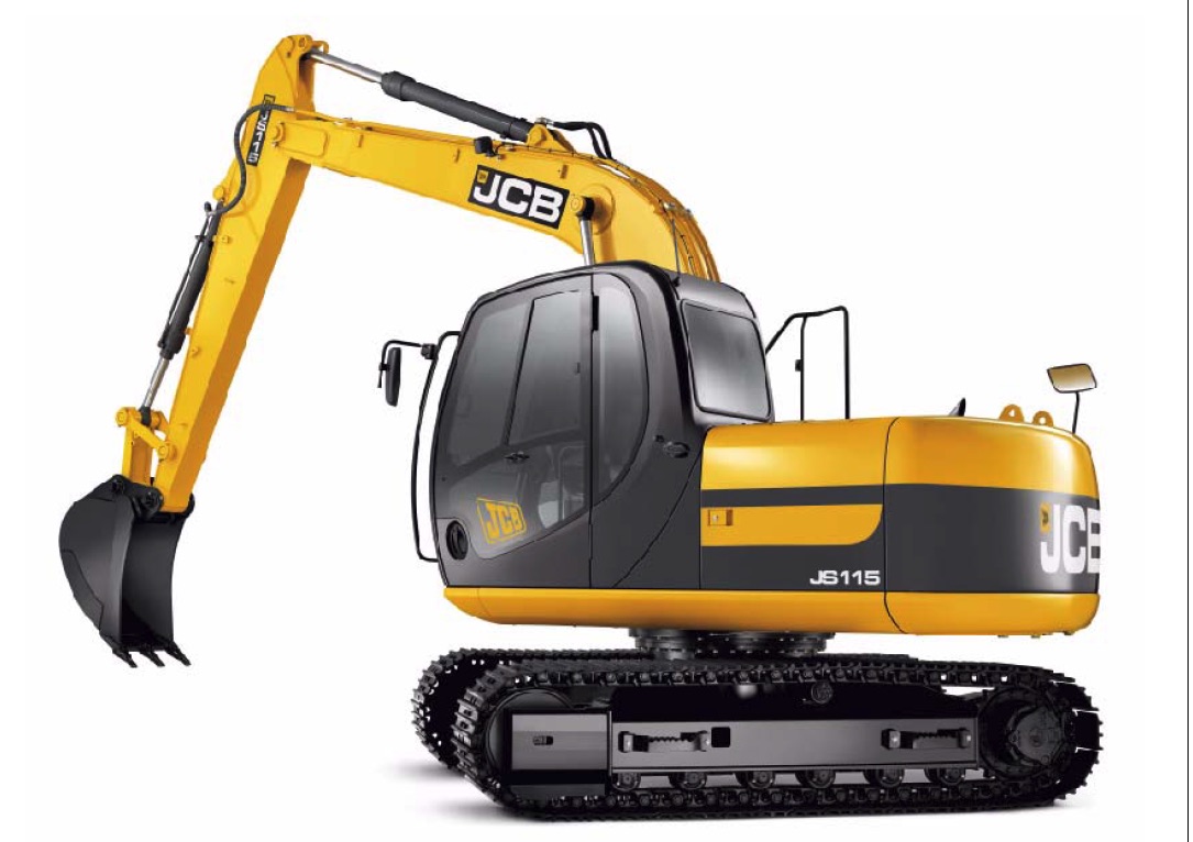
Complete workshop & service manual with electrical wiring diagrams for JCB Hydraulic Excavators JS130W, JS145W, JS150W, JS160W, JS175W. It’s the same service manual used by dealers that guaranteed to be fully functional and intact without any missing page.

This JCB Hydraulic Excavators JS130W, JS145W, JS150W, JS160W, JS175W service & repair manual (including maintenance, overhaul, disassembling & assembling, adjustment, tune-up, operation, inspecting, diagnostic & troubleshooting…) is divided into different sections. Each section covers a specific component or system with detailed illustrations. A table of contents is placed at the beginning of each section. Pages are easily found by category, and each page is expandable for great detail. The printer-ready PDF documents work like a charm on all kinds of devices.

FILELIST:
9803-6300 – JCB Hydraulic Excavators JS130W, JS150W Service Manual.pdf
9803-6310 – JCB Hydraulic Excavators JS130W, JS145W, JS160W, JS175W Service Manual.pdf
9803-6550 – JCB Hydraulic Excavators JS175W Auto Service Manual.pdf
9803-6590 – JCB Hydraulic Excavators JS130W, JS145W, JS160W, JS175W Service Manual.pdf
9813-1700 – JCB Tracked Excavators JS Auto Range JS145W-JS160W & Variants (JCB Engine) Service Manual.pdf

EXCERPT:
Service Manual
JS Auto Range – Wheeled Excavators –
JCB Engine
Section 1 – General Information
Section 2 – Care & Safety
Section 3 – Maintenance
Section B – Body & Framework
Section C – Electrics
Section D – Controls
Section E – Hydraulics
Section F – Transmission
Section K – Engine

Section E – Hydraulics
Drive Motor
Operation
Fig 1. Operation below 210bar
Fig 2. Operation at high pressure – 220bar
Under normal non-inclined road conditions, oil enters at ports A and B (depending on the drive direction). At port A, oil pressure moves the shuttle and oil flows at system pressure to act on the threshold piston. The oil is allowed to pass through the motor and back to tank.
Oil is available to the brake spool section. The flow is deadended at a check valve, but is available at the spool end, where it selects a spool. Oil passes through the other check valve, where it is dead-ended by the selected spool.
When the machine encounters an incline however, the operation changes. Oil still flows through the motor but, as the pressure starts to build up from the effect of the incline, this pressure starts to be felt at CV1 which allows oil to pass, at CV2, which closes off, the supply to the filter, through the orifice, across the spool to a, Max speed /Min Flow side of the piston. The piston holds Max speed.
The pressure is felt at the spool end, but the spool does not select as the spring pressure holds it stationary. Oil from the other side of the piston is open to tank. As the pressure rises to match and overcome the spring pressure (threshold pressure), the spool will start to select.
The oil flow across the spool changes direction to feed the b Min speed/Max flow side of the piston, this moving the piston in the opposite direction altering the swash angle to give maximum torque. The max side of the piston is then open to tank. The spool shuttles to match torque with road conditions.
When the machine travels down hill, the motor operation acts as a pump, the oil supply is insufficient to prevent cavitation within the motor. Negative pressure can lift the check valve and allow oil from tank to make up and prevent cavitation.The restrictions within the brake spool give the motor its braking effect by slowing the oil as it returns to tank.
Ports on Motor Body

Posted on

JCB JS115, JS130, JS130LC, JS145, JS160, JS180, JS190, JS200, JS210, JS220 Hydraulic Excavator Factory Service & Shop Manual


JCB JS115, JS130, JS130LC, JS145, JS160, JS180


INSTANT DOWNLOAD


Complete workshop & service manual with electrical wiring diagrams for JCB JS115, JS130, JS130LC, JS145, JS160, JS180, JS190, JS200, JS210, JS220 Hydraulic Excavator. It’s the same service manual used by dealers that guaranteed to be fully functional and intact without any missing page.

This JCB JS115, JS130, JS130LC, JS145, JS160, JS180, JS190, JS200, JS210, JS220 Hydraulic Excavator service & repair manual (including maintenance, overhaul, disassembling & assembling, adjustment, tune-up, operation, inspecting, diagnostic & troubleshooting…) is divided into different sections. Each section covers a specific component or system with detailed illustrations. A table of contents is placed at the beginning of each section. Pages are easily found by category, and each page is expandable for great detail. The printer-ready PDF documents work like a charm on all kinds of devices.

FILE LIST:
9803-6410 – JCB Hydraulic Excavators JS130, JS160 Service Manual.pdf
9803-6520 – JCB Hydraulic Excavator JS115, JS130, JS130LC, JS145, JS160, JS180 Service Manual.pdf
9803-6570 – JCB Hydraulic Excavators JS160, JS180, JS190 Tier III Auto Service Manual.pdf
9813-1000 – JCB JS Auto Range JS115, JS130, JS145, JS160, JS180, JS200, JS210, JS220 Tracked Excavators (JCB Engine) Service Manual.pdf

EXCERPT:
TABLE OF CONTENTS
Section 1 – General Information
Section 2 – Care and Safety
Section 3 – Routine Maintenance
Section B – Body & Framework
Section C – Electrics
Section E – Hydraulics
Section F – Transmission
Section J – Track and Running Gear
Section K – Engine

Section E – Hydraulics
Hydraulic Rams Precautions During Use

Installation
1 Precautions when installing the ram on the machine.
a When installing and removing from the machine, suspend the ram safely.
b Suspending the ram by the piping is not only dangerous, but can also cause damage to the cylinder.
c Secure the piston rod with a band. It is very dangerous if the rod extends unexpectedly. Also, the rod can be damaged and become unusable.
2 Welding after installing the ram may result in damage.
a If electric welding is done even at a point away from the ram, there may be sparking inside the ram and it will become necessary to replace the ram with a new one.
3 When painting the machine, mask the ram.
a If paint adheres to the rod surface or to the wiper ring and the ram is operated, the wiper ring will not function properly and foreign matter and paint can easily enter the ram. This will cause damage to the seals, drastically shortening the life of the ram.
4 Install the ram only when it is clean.

Caution During Use
1 Use only under designated conditions.
a If hydraulic oil other than the designated oil is used, the seals quickly degenerate and become damaged. If the relief valve is set at a value higher than specified, it may cause ram damage and is dangerous.
b In high temperature environments (approx. 90°C and above) or low temperature environments (below -20°C), seals quickly become damaged.
Special seal materials are necessary so check to see if the ram that you are using is suitable or not.
c The number one cause of ram oil leakage is rod damage. Be careful not to damage the rod.
2 Warm up sufficiently before beginning work.
a In cold conditions the rod seals may be frozen, so if the ram is operated at maximum pressure and maximum speed, the seals will be damaged.
b There is a large amount of air in a new ram or one which has been left for a long time, so the ram will not operate smoothly. Also, if pressure is applied suddenly without bleeding the air, high temperatures will be generated due to adiabatic compression and the seals may burn.
c Before beginning work, always move the ram at full stroke with no load and expel air from the cylinder.
3 When stopping or storing, do it at a safe and fixed position.
a The installed ram cannot maintain the same position for a long period of time, because the oil inside the ram may leak and the hydraulic oil volume decreases as it cools. Stop or store the machine in a safe and fixed position.
Maintenance, Inspection Points
1 Carry out daily maintenance and inspection.


INSTANT DOWNLOAD


Posted on

JCB Hydraulic Excavator JS70/JS110/JS115/JS120/JS130/JS145/JS150 Factory Service & Shop Manual


Pages from 9803-9860 – JCB Hydraulic Excavator JS115, JS130, JS145 Tier III Auto Service Manual


INSTANT DOWNLOAD


Complete workshop & service manual with electrical wiring diagrams for JCB Hydraulic Excavator JS70, JS110, JS115, JS120, JS130, JS145, JS150LC. It’s the same service manual used by dealers that guaranteed to be fully functional and intact without any missing page.

This JCB Hydraulic Excavator JS70, JS110, JS115, JS120, JS130, JS145, JS150LC service & repair manual (including maintenance, overhaul, disassembling & assembling, adjustment, tune-up, operation, inspecting, diagnostic & troubleshooting…) is divided into different sections. Each section covers a specific component or system with detailed illustrations. A table of contents is placed at the beginning of each section. Pages are easily found by category, and each page is expandable for great detail. The printer-ready PDF documents work like a charm on all kinds of devices.

FILE LIST:
9803-6020 – JCB Hydraulic Excavator JS70 (from machine no. 695501) Service Manual.pdf
9803-6100 – JCB Hydraulic Excavator JS110, JS130, JS150LC Service Manual.pdf
9803-9860 – JCB Hydraulic Excavator JS115, JS130, JS145 Tier III Auto Service Manual.pdf
9813-1300 – JCB Hydraulic Excavator JS120 Service Manual.pdf

EXCERPT:
Service Manual
JS 120
Service Manual – JS 120
Section 1 – General Information
Section 2 – Care and Safety
Section 3 – Maintenance
Section B – Body and Framework
Section C – Electrics
Section E – Hydraulics
Section F – Transmissions
Section J – Track and Running Gear
Section K – Engine

Service Manual
JS115,JS130,JS145 – Tier III Auto
Service Manual – JS115,JS130,JS145 – Tier III Auto
Section 1 – General Information
Section 2 – Care & Safety
Section 3 – Maintenance
Section B – Body & Framework
Section C – Electrics
Section E – Hydraulics
Section F – Transmission
Section J – Track & Running Gear
Section K – Engine

Slew Speed
1 Position the dig end in the minimum slew position facing forwards.
2 Rotate the upper framework and after one complete rotation measure the time it takes for the next 5 rotations. Calculate the speed of one rotation.
Travel Speed
1 Raise one track off the ground by slewing the machine through 90 degrees and lifting the machine using the boom and dipper.
2 Make a mark on the outside edge of the track gearbox.
3 Operate the track motor in forward and reverse for 5 minutes, changing gear at regular intervals to distribute warm oil through the system.
4 Record the time it takes for the motor to complete ten revolutions. Calculate the gearbox speed.
Measure the speed in each direction three times and calculate the average speed.
Travel Linearity
The machine should have an approach A of 5 metres (16.5 ft) and a travel distance B of 20 metres (65.62 ft).


INSTANT DOWNLOAD


Posted on

JCB Hammermaster, Rockbreakers, HM Range Medium, Large Hydraulic Breakers Factory Service & Shop Manual


Pages from 9803-1420 – JCB HM Range Medium, Large Hydraulic Breakers Service Manual

MJCBBREAKEROPES.zip
Price: $29.99 USD

Complete workshop & service manual with electrical wiring diagrams for JCB Hammermaster, Rockbreakers, HM Range Medium, Large Hydraulic Breakers. It’s the same service manual used by dealers that guaranteed to be fully functional and intact without any missing page.

This JCB Hammermaster, Rockbreakers, HM Range Medium, Large Hydraulic Breakers service & repair manual (including maintenance, overhaul, disassembling & assembling, adjustment, tune-up, operation, inspecting, diagnostic & troubleshooting…) is divided into different sections. Each section covers a specific component or system with detailed illustrations. A table of contents is placed at the beginning of each section. Pages are easily found by category, and each page is expandable for great detail. The printer-ready PDF documents work like a charm on all kinds of devices.

FILELIST:
9803-1300 – JCB Hammermaster, Rockbreakers Service Manual.pdf
9803-1420 – JCB HM Range Medium, Large Hydraulic Breakers Service Manual.pdf

EXCERPT:
Contents Page No.
Hammermaster Identification 1 – 1
Torque Settings
Hammermaster 360 Range 2 – 1
Hammermaster 460-110 2 – 3
Hammermaster 560 2 – 4
Hammermaster 660 2 – 5
Hammermaster 760 2 – 6
Hammermaster 860 2 – 7
Hammermaster 960 2 – 8
Hammermaster 160 Range 2 – 9
Hammermaster 260 Range 2 – 10
Hammermaster 570 2 – 11
Hammermaster 670 2 – 12
Hammermaster 770 2 – 13
Hammermaster 1050, 1150 2 – 14
Hammermaster 1350, 1450 2 – 15
Hammermaster 1750 2 – 16
Hammermaster 2350/2950/3850/3950 2 – 17
Hammermaster 550 2 – 18
Hammermaster 850 2 – 19
Service Tools 3 – 1
Nord-Lock Washers 3 – 1
Accumulator Charging 3 – 2
Safety Notices 4 – 1
General Safety 5 – 1
Operating Safety 6 – 1
Maintenance Safety 7 – 1
Safety Decals 8 – 1
Lubricants – Health and Safety 9 – 1
Note: Hammermaster 70 – All Service Information relating to this hammer is contained in Section 13. Safety requirements are retained in this section.
Note: Hammermaster 100 and Hammermaster 115 – All Service
Information relating to these hammers is contained in Section 20.
Safety requirements are retained in this section.

Contents Page No.
i i
Medium Breakers
Introduction …………1
Safety ….1
General Information …..1
Workshop Standards …………..1
Spare Parts …….1
Service Personnel …….1
Using this Manual ……..2
Standard Symbols …………3
Service Tools ………5
Charging Equipment …….10
Medium Breakers – HM165Q, 265Q, 385Q, 495Q
Dismantling ………. 11
Assembly ………….18
Field Bushing Exchange …………23
Charging the Accumulator ………25
Hanger Brackets ………….27
Exploded Views …………..28
Operating Principles …….32
Stage 1 – Start Up ……32
Stage 2 – Return Stroke ……..32
Stage 3 – Power Stroke ………33
Stage 4 – End of Power Stroke ……..33
Medium Breakers – HM386Q
Special Tools …….34
Dismantling ……….38
Assembly ………….45
Operating Principles …….54
Stage 1 ………..54
Stage 2 ………..54
Stage 3 ………..55
Stage 4 ………..55
Stage 5 ………..56
Medium Breakers
Technical Specifications …………57
Nitrogen Adaptor Reference Chart …….58
Tool Part Numbers ……….63
Breaker Part Number Matrix ……64

Chapter Title Page
Introduction
1 General 1
1.1 Explanation of the symbols in the repair manual 1
Safety
2 Operational safety 2
2.1 General 2
2.2 Accident prevention regulations 2
2.3 Safety Notices 3
Tools
3 Tools 5
3.1 General tools 5
3.2 Service box 6
3.3 Special accessories 7
3.3.1 Accumulator charging device 7
3.3.2 Power wrench 8
3.3.3 HeliCoil-tools 8
3.3.4 Fitting aid for piston 9
3.3.5 Press-out aid for wear bushes 9
3.4 Consumables 10
Technical Specifications
4 Technical Specifications 11
4.1 Breaker Specifications 11
4.2 Working Pressure/Required Flow/Engine RPM 16
Dismantling
5 Dismantling the Hydraulic Breaker 21
5.1 Fitting/Removing the Tool 21
5.2 Removing the Power Cell from the Hammer Housing 22
5.3 Removing the High-Pressure Accumulator 23
5.4 Removing the Control System 24
5.5 Removing the Control Slide Valve 24
5.6 Removing the Frequency Switching System 25
5.7 Removing the Cylinder Cover 26
5.8 Removing the Piston and sealing Bush 28
5.9 Removing the Cylinder 28
5.10 Removing the Locking Pins for the Retainer Bars in the Lower Breaker Part 29
5.11 Removing the Locking Bushes 29
Checking
6 Checking the Hammer Housing 30
6.1 Checking for Cracks and Indentations 30
6.2 Wear to the Bottom Plate 30
6.3 Checking the Elastic Pad 31
6.4 Checking the Damping Elements 31
6.5 Checking the Guide Plates 32
6.6 Checking the Tool for Wear 33
Assembling
7 Assembling the Hydraulic Hammer 34
7.1 Tightening Torques for Screws and Screw Couplings on the JCB HM 860Q 34
7.2 Tightening Torques for Screws and Screw Couplings on the JCB HM 1260Q 35
7.3 Tightening Torques for Screws and Screw Couplings on the JCB HM 1560Q 36
7.4 Tightening Torques for Screws and Screw Couplings on the JCB HM 1760Q 37
7.5 Tightening Torques for Screws and Screw Couplings on the JCB HM 2460Q 38
7.6 Tightening Torques for Screws and Screw Couplings on the JCB HM 3060Q and JCB HM
4160Q
39
7.7 Fitting the Cylinder 40
7.8 Fitting the Piston and sealing Bush 40
7.9 Fitting the Cylinder Cover 41
7.10 Fitting the Frequency Switching System 43
7.11 Fitting the Control Slide Valve 44
7.12 Fitting the Control System 44
7.13 Fitting the High-Pressure Accumulator 45
7.14 Checking Pressure in piston Accumulator and Refilling if Required 46
7.15 Fitting the Power Cell into the Hammer Housing 48
7.16 Connecting the JCB AUTOGREASE 49
7.17 Fitting the Tool 50
Changing Seals
8 Changing the Seals 51
8.1 Changing the Cylinder Seals 51
8.2 Changing the Seals between Cylinder and Cylinder Cover 53
8.3 Changing the Seals on the Control System 53
8.4 Changing the Seals on the High Pressure Accumulator 54
8.5 Changing the seals on the Sealing Bush 54
Repair Work
9 Repair Work 55
9.1 Changing the Expansion Bolts on the High-Pressure Accumulator 55
9.2 Changing the High-Pressure Accumulator 55
9.3 Changing the Tie Rods 56
9.4 Removing Scores from Control slide Valve and Bore 57
9.5 Removing Scores on Piston and Cylinder Bore 57
9.6 Changing the Wear Bushes 58
9.7 Replacing the Complete Housing 60
9.8 Replacing Guide Plates and Damping Elements in Housing 60
9.9 Repairing Cracked Welds 61
9.10 Replacing the Bottom Plate on the Housing 61
9.11 Reworking the Retainer Pins for the Damping Elements 62
9.12 Weld Seam Preparation 62
9.13 Preheating Temperature 62
9.14 Fillers 62
9.15 Post-treatment of Welds 62
Spares List
10 Spares List 63
10.1 Percussion Unit 63
10.2 Noise Damping 64
10.3 JCB AUTOGREASE 65
Appendices
1 Breaker Operating Principles 67
2 JCB Autogrease Operating Principles 75
Nitrogen Adaptor Reference Chart
11 Nitrogen Adaptor Reference Chart 90
Tool Part Numbers
12 Tool Part Numbers 92
Breaker Part Number Matrix
13 Breaker Part Number Matrix 93

Posted on

JCB Groundhog/Ground Care/Workmax Factory Service & Shop Manual


Pages from 9813-0450- JCB Workmax 800D Service Manual

MJCBGRUNDOPES.zip
Price: $29.99 USD

Complete workshop & service manual with electrical wiring diagrams for JCB Groundhog 6×4, Groundhog 4×4, Ground Care FM25, Ground Care FM30, Workmax 800D. It’s the same service manual used by dealers that guaranteed to be fully functional and intact without any missing page.

This JCB Groundhog 6×4, Groundhog 4×4, Ground Care FM25, Ground Care FM30, Workmax 800D service & repair manual (including maintenance, overhaul, disassembling & assembling, adjustment, tune-up, operation, inspecting, diagnostic & troubleshooting…) is divided into different sections. Each section covers a specific component or system with detailed illustrations. A table of contents is placed at the beginning of each section. Pages are easily found by category, and each page is expandable for great detail. The printer-ready PDF documents work like a charm on all kinds of devices.

FILELIST:
9803-9390 – JCB Groundhog 6×4 Service Manual.pdf
9803-9820 – JCB Groundhog 4×4 Service Manual.pdf
9803-9830 – JCB Ground Care FM30 Service Manual.pdf
9803-9840 – JCB Ground Care FM25 Service Manual.pdf
9813-0450- JCB Workmax 800D Service Manual.pdf

EXCERPT:
Service Manual
Groundhog 6×4
Section 1 – General Information
Section 2 – Care and Safety
Section 3 – Routine Maintenance
Section A – Optional Equipment
Section B – Body and Framework
Section C – Electrics
Section D – Controls
Section E – Hydraulics
Section F – Transmission
Section G – Brakes
Section H – Steering
Section K – Engine
Section S – Suspension

Service Manual
Workmax 800D
Section 1 – General Information
Section 2 – Care and Safety
Section 3 – Maintenance
Section B – Body and Framework
Section C – Electrics
Section D – Controls
Section F – Transmission
Section G – Brakes
Section H – Steering
Section K – Engine
Section S – Suspension

Adjustment
Rear Axle Sensor
1 Align the gear tooth C with the speed sensor B by turning the rear axle.
2 Remove the sensor from the casing.
3 Screw the sensor B into the casing by hand clockwise until resistance is felt.
4 Unscrew the sensor counter clockwise by 1 to 2 turns.
5 Tighten the securing nut A.