Complete workshop & service manual with electrical wiring diagrams for JCB 427, 437, 457 Wheeled Loading Shovel. It’s the same service manual used by dealers that guaranteed to be fully functional and intact without any missing page.
This JCB 427, 437, 457 Wheeled Loading Shovel service & repair manual (including maintenance, overhaul, disassembling & assembling, adjustment, tune-up, operation, inspecting, diagnostic & troubleshooting…) is divided into different sections. Each section covers a specific component or system with detailed illustrations. A table of contents is placed at the beginning of each section. Pages are easily found by category, and each page is expandable for great detail. The printer-ready PDF documents work like a charm on all kinds of devices.
FILELIST:
9813-1600 – JCB 427, 437, 457 Wheeled Loading Shovel Service Manual.pdf
EXCERPT:
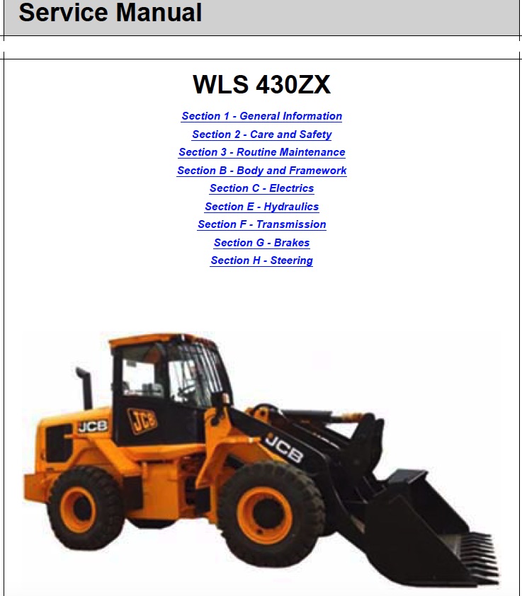
Service Manual
Wheeled Loading Shovel – 427, 437 and 457
Section 1 – General Information
Section 2 – Care and Safety
Section 3A – Routine Maintenance
Section 3B – Routine Maintenance
Section A – Attachments
Section B – Body and Framework
Section C – Electrics
Section E – Hydraulics
Section F – Transmission
Section G – Brakes
Section H – Steering
Section K – Engine
…
Machine Model and Serial Number
This manual provides information for the following
model(s) in the JCB machine range:
– 427 T4i from 2063050
– 437 T4i from 2063202
– 457 T4i from 1907000.
…
Hydraulic Control Unit
Dismantling
K Fig 441. ( T F-149).
1 Match-mark relative to each other the relevant positions of valve housing 1, housing covers 12 and 15, and end covers 2 and 3.
2 Remove socket head screws 5.
Separate duct plate 6, gasket 7, intermediate plate 8 and gasket 9 from the valve housing.
3 Remove retaining clip 10.
4 Remove socket head screws 11 and 14.
Separate cover 2 and gasket 2A from housing 12 and cable harness 4. Separate cover 3 and gasket 3A from housing 15.
5 Disconnect cable harness 4 from the pressure regulators 17 (3 off) and 29 (3 off) and remove.
6 Remove the three socket head screws 18, fixing plates 19 and pressure regulators 17.
7 Remove the two outermost socket head screws 20 and replace provisionally with adjusting screws.
Remove the remaining socket head screws 20.
8 Separate housing 12 and gasket 13 from valve housing 1 by loosening the compression tools uniformly to release the spring loading.
9 Remove components 21/22 (1 off), 23/24 (3 off) and -25/ 26 (3 off).
10 Remove the three socket head screws 27, fixing plates 28 and pressure regulators 29.
11 Remove the two outermost socket head screws 30 and replace provisionally with adjusting screws (M5).
Remove the remaining socket head screws 30.
12 Separate housing 15 and gasket 16 from valve housing 1 by loosening the adjusting screws uniformly to release the spring loading.
13 Remove components 441-31/32 (1 off), 441-33/34 (3 off) and 441-35/ 36 (3 off).
…