Posted on

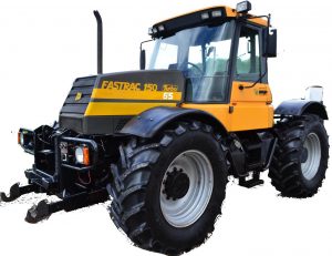
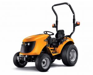
JCB 323HST, 327HST Groundcare Tractors Factory Service & Shop Manual


Pages from 9803-9470 – JCB 323HST, 327HST Groundcare Tractors Service Manual

MJCB323HST327OPES.zip
Price: $29.99 USD

Complete workshop & service manual with electrical wiring diagrams for JCB 323HST, 327HST Groundcare Tractors. It’s the same service manual used by dealers that guaranteed to be fully functional and intact without any missing page.

This JCB 323HST, 327HST Groundcare Tractors service & repair manual (including maintenance, overhaul, disassembling & assembling, adjustment, tune-up, operation, inspecting, diagnostic & troubleshooting…) is divided into different sections. Each section covers a specific component or system with detailed illustrations. A table of contents is placed at the beginning of each section. Pages are easily found by category, and each page is expandable for great detail. The printer-ready PDF documents work like a charm on all kinds of devices.

9803-9470 – JCB 323HST, 327HST Groundcare Tractors Service Manual.pdf

EXCERPT:
Section 1 – General Information
Section 2 – Care and Safety
Section 3 – Maintenance
Section A – Attachments
Section C – Electrics
Section E – Hydraulics
Section F – Gearboxes
Section G – Brakes
Section H – Steering
Section K – Engine

Diff Case and Bevel Pinion
1 Apply grease to each friction surface.
2 The bevel pinion and the ring gear are paired after mesh adjustment is performed at the factory. When reassembling the pair, make sure to pair parts with a same reference number.
3 When installing the taper roller bearings on the bevel pinion, make sure you install a new lock nut and secure it as shown K Fig 73. ( T F-69).
4 Install the snap ring and install the bevel pinion together with the taper roller bearings K Fig 75. ( T F-71).
5 Install the bearings in the axle housing and assemble the ring gear in the axle housing.
Fig 75.
6 Install a new parallel pin 4.
7 When either the bevel pinion, ring gear, taper roller bearing, collar etc. have been replaced, check the bevel pinion assembly (through the drain plug hole) for the specified thrust play of 0.1 – 0.2 mm (0.004 -0.008 in) in the front axle housing.

Posted on

JCB 225, 225T, 260, 260T, 280, 300, 300T, 320T, 330 Skid Steer Factory Service & Shop Manual


Pages from 9803-9950 – Skid Steer Large Platform 225, 225T, 260, 260T, 280, 300, 300T, 320T, 330 Service Manual

MJCB225LP330OPES.zip
Price: $29.99 USD

Complete workshop & service manual with electrical wiring diagrams for JCB Skid Steer Large Platform 225, 225T, 260, 260T, 280, 300, 300T, 320T, 330. It’s the same service manual used by dealers that guaranteed to be fully functional and intact without any missing page.

This JCB Skid Steer Large Platform 225, 225T, 260, 260T, 280, 300, 300T, 320T, 330 service & repair manual (including maintenance, overhaul, disassembling & assembling, adjustment, tune-up, operation, inspecting, diagnostic & troubleshooting…) is divided into different sections. Each section covers a specific component or system with detailed illustrations. A table of contents is placed at the beginning of each section. Pages are easily found by category, and each page is expandable for great detail. The printer-ready PDF documents work like a charm on all kinds of devices.

9803-9950 – Skid Steer Large Platform 225, 225T, 260, 260T, 280, 300, 300T, 320T, 330 Service Manual.pdf

EXCERPT:
Skid Steer Large Platform
Service Manual – Skid Steer Large Platform
Section 1 – General Information
Section 2 – Care and Safety
Section 3 – Maintenance
Section A – Attachments
Section B – Body and Framework
Section C – Electrics
Section E – Hydraulics
Section F – Transmission
Section J – Tracks
Section K – Engine

Bleeding the System
To bleed the engine fuel filter carry out the following:
1 Make the machine safe with the arm lowered.
Prepare the Machine for Maintenance ( T 3-21)
2 Loosen bleed screw K.
3 Operate the fuel lift pump priming button J until air free fuel exits from the bleed screw.
Catch any excess fuel with a suitable container.
4 Tighten the bleed screw.
!MCAUTION
Running the engine with air in the system could damage the fuel injection pump. After maintenance, the system must be bled to remove any air.
5 The engine is now ready to start. If the engine runs smoothly for a short time and then begins to run roughly, leave at idle until it runs smoothly.
6 If the engine continues to run roughly, check again for air in the fuel system.
7 If the fault persists contact your nearest JCB dealer.

Posted on

JCB ROBOT 185, 190, 1100, 1105 Factory Service & Shop Manual


Pages from 9803-9460 – JCB Robot 190, 1110 Service Manual

MJCB185ROB1105OPES.zip
Price: $29.99 USD

Complete workshop & service manual with electrical wiring diagrams for JCB ROBOT 185, 190, 1100, 1105. It’s the same service manual used by dealers that guaranteed to be fully functional and intact without any missing page.

This JCB ROBOT 185, 190, 1100, 1105 service & repair manual (including maintenance, overhaul, disassembling & assembling, adjustment, tune-up, operation, inspecting, diagnostic & troubleshooting…) is divided into different sections. Each section covers a specific component or system with detailed illustrations. A table of contents is placed at the beginning of each section. Pages are easily found by category, and each page is expandable for great detail. The printer-ready PDF documents work like a charm on all kinds of devices.

FILELIST:
9803-8510 – JCB ROBOT 185, 1105 Service Manual.pdf
9803-8530 – JCB ROBOT 190, 1100 Service Manual.pdf
9803-8530 (Issue 8) – JCB ROBOT 190, 1100 Service Manual.pdf
9803-9460 – JCB Robot 190, 1110 Service Manual.pdf

EXCERPT:
Service Manual
JCB Robot 190 and 1110
Section 1 – General Information
Section 2 – Care and Safety
Section 3 – Maintenance
Section A – Attachments
Section B – Body and Framework
Section C – Electrics
Section D – Controls
Section E – Hydraulics
Section F – Transmission
Section G – Brakes
Section J – Tracks
Section K – Engine

Tracks
Track Adjustment
Correct track tension is important for good performance and to prevent the tracks from dismounting. The track tension is controlled by the forward idler which is attached to a grease filled hydraulic cylinder. The track tension should be checked as follows:
1 Position machine on a smooth flat surface
2 Thoroughly clean the track, making sure that all debris is removed from around the sprocket and rollers. Drive the machine backwards and forwards whilst cleaning.
3 Drive the machine forwards to ensure that the slack is at the top of the track.
4 Using a suitable straight edge, measure the sag at position B which should be 5 to 10 mm (0.2 to 0.4 in).
5 If adjustment is required, unscrew bolts C and remove access plate D.
6 To tighten the track, pump grease into nipple E using a grease gun. To loosen the track, carefully unscrew hexagon plug F and allow the grease to flow into a suitable container.
7 When correct adjustment is achieved, replace the cover plate.
8 Repeat for opposite track.

Posted on

JCB Skid Steer Loader Range ROBOT 150, 160, 165, 170, 180 Factory Service & Shop Manual


Pages from 9803-9450 – JCB ROBOT 160, 170, 180 Service Manual


INSTANT DOWNLOAD


Complete workshop & service manual with electrical wiring diagrams for JCB Skid Steer Loader Range ROBOT 150, ROBOT 160, ROBOT 165, ROBOT 170, ROBOT 180. It’s the same service manual used by dealers that guaranteed to be fully functional and intact without any missing page.

This JCB Skid Steer Loader Range 150, 160, 165, 170, 180 service & repair manual (including maintenance, overhaul, disassembling & assembling, adjustment, tune-up, operation, inspecting, diagnostic & troubleshooting…) is divided into different sections. Each section covers a specific component or system with detailed illustrations. A table of contents is placed at the beginning of each section. Pages are easily found by category, and each page is expandable for great detail. The printer-ready PDF documents work like a charm on all kinds of devices.

FILE LIST:
9803-8500 – JCB ROBOT 150, 165 Service Manual.pdf
9803-8520 – JCB ROBOT 160, 170, 180T Service Manual.pdf
9803-9450 – JCB ROBOT 160, 170, 180 Service Manual.pdf

EXCERPT:
General Information 1
Care & Safety 2
Routine Maintenance 3
Attachments A
Body & Framework B
Electrics C
Controls D
Hydraulics E
Transmission F
Brakes G
Engine K

Service Manual
JCB Robot 160, 170 and 180
Section 1 – General Information
Section 2 – Care and Safety
Section 3 – Maintenance
Section A – Attachments
Section B – Body and Framework
Section C – Electrics
Section D – Controls
Section E – Hydraulics
Section F – Transmission
Section G – Brakes
Section J – Tracks
Section K – Engine

Machine Model and Serial Number
This manual provides information for the following wheeled models in the JCB Skid Steer Loader Range.
– Robot 160 serial number 1602000 to 1604999.
– Robot 160HF serial number 1602000 to 1604999.
– Robot 170 serial number 1602000 to 1604999.
– Robot 170HF serial number 1602000 to 1604999.
– Robot 180 serial number 1602000 to 1604999.
– Robot 180HF serial number 1602000 to 1604999.
This manual also provides information for the following tracked models in the JCB Skid Steer Loader Range.
– Robot 180T serial number 1803000 to 1806999.
– Robot 180T HF serial number 1803000 to 1806999.
Information also covers both wheeled and tracked machines unless otherwise stated.

Track Frame Assembly
Removal
Fig 32.
1 Raise and support the machine and remove the track (see K Removal ( T J-15)).
2 Disconnect the motor feed and return hoses having marked them for correct reconnection.
3 Sling the track frame as shown and support the weight using a suitable hoist.
4 Remove the bolts from the front mounting.
5 Remove the bolts from the rear mounting. It will be necessary to release the top two bolts gradually whilst easing the frame away from the machine.
!MCAUTION
Do not pull the frame too far away otherwise the hoses will rip off.
6 Once access has been gained, disconnect the motor drain and brake hoses having marked them for correct reconnection.
7 Manoeuvre the track frame away from the machine.


INSTANT DOWNLOAD


Posted on

JCB 135, 155, 175, 190, 205, 150T, 190T, 205T Skid Steer Small Platform Factory Service & Shop Manual


JCB Fastrac 125, 135, 145, 150, 155, 185

MJCB135SP205OPES.zip
Price: $29.99 USD

Complete workshop & service manual with electrical wiring diagrams for 135, 155, 175, 190, 205, 150T, 190T, 205T Skid Steer Small Platform. It’s the same service manual used by dealers that guaranteed to be fully functional and intact without any missing page.

This JCB 135, 155, 175, 190, 205, 150T, 190T, 205T Skid Steer Small Platform service & repair manual (including maintenance, overhaul, disassembling & assembling, adjustment, tune-up, operation, inspecting, diagnostic & troubleshooting…) is divided into different sections. Each section covers a specific component or system with detailed illustrations. A table of contents is placed at the beginning of each section. Pages are easily found by category, and each page is expandable for great detail. The printer-ready PDF documents work like a charm on all kinds of devices.

9813-1350-2 – 135, 155, 175, 190, 205, 150T, 190T, 205T Skid Steer Small Platform Service Manual

EXCERPT:
Skid Steer Small Platform
Service Manual – Skid Steer Small Platform
Section 1 – General Information
Section 2 – Care and Safety
Section 3 – Maintenance
Section A – Attachments
Section B – Body and Framework
Section C – Electrics
Section E – Hydraulics
Section F – Transmission
Section J – Tracks
Section K – Engine

Removal and Replacement
Removal
Note: Only the left-hand (L.H.) joystick is shown in the illustration K Fig 2. ( T E-53). The other joystick is removed and replaced in the same way.
Ensure that the engine is stopped and all hydraulic pressure is released from the system.
!MWARNING
It is not possible to vent all residual pressure. Loosen the connection one full turn and allow the pressure to dissipate. Keep face and hands well clear of
pressurised hydraulic oil and wear protective glasses.
HYD-4-3
Remove the covers from around the joystick body.
Mark the joystick flange and supporting flange to ensure correct realignment on replacement.
Label then remove hydraulic hoses and plug exposed connections to prevent ingress of dirt and water.
Disconnect the electrical connection if fitted.
Remove four screws 1 and washers 2, lift the joystick unit clear.
Replacement
Replacement is a reversal of the removal procedure.
Torque tighten hydraulic connections to 30 Nm (22 lbf ft).
Torque tighten screws 1 (4 off) to 10 Nm (7 lbf ft).
Reconnect the electrical connection if fitted. Replace covers around the joystick body.