Posted on

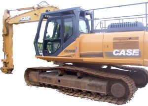
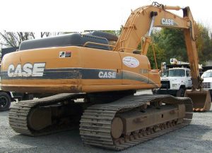
Case CX290B Crawler Excavators Workshop Repair & Service Manual


Case CX290B

MCSCX290BOPES.zip
Price: $29.99 USD

Complete digital official shop manual contains service, maintenance, and troubleshooting information for the Case CX290B Crawler Excavators. Diagnostic and repair procedures are covered in great detail to repair, maintain, rebuild, refurbish or restore your Case CX290B Crawler Excavators like a professional mechanic in local service/repair workshop. This cost-effective quality manual is 100% complete and intact as should be without any missing pages. It is the same factory shop manual used by dealers that guaranteed to be fully functional to save your precious time.

This manual for Case CX290B Crawler Excavators is divided into different sections. Each section covers a specific component or system and, in addition to the standard service procedures, includes disassembling, inspecting, and assembling instructions. A table of contents is placed at the beginning of each section. Pages are easily found by category, and each page is expandable for great detail. It is in the cross-platform PDF document format so that it works like a charm on all kinds of devices. You do not need to be skilled with a computer to use the manual.

“87673891 B.pdf”
Case CX290B Crawler Excavators Service Manual
Replaces 87673891
Issued February 2010
87673891 B

EXCERPT:
TABLE OF CONTENTS
DIVISION/SECTION SECTION N° REFERENCE N°
1 GENERAL INFORMATION
Safety, general information and standard torque data 1001 7-27691EN
General specifications and special torque setting 1002 SM290B1002-1NA
2 ENGINE
Removal and installation of the engine 2000 SM290B2000-0EN
Removal and installation of the fuel cooler, engine inter-cooler, radiator and oil cooler. 2001 SM290B2001-0EN
Removal and installation of the turbo charger 2004 SM290B2004-0EN
Removal and installation of EGR cooler and EGR valve 2005 SM350B2005-0EN
Removal and installation of the engine hood 2006 SM350B2006-0EN
Engine specifications.*
Disassembly and assembly of the engine *
3 FUEL SYSTEM
Removal and installation of the fuel tank. 3001 SM290B3001-0EN
Removal and installation of the supply pump and common rail 3004 SM290B3004-0EN
Removal and installation of the injectors – 3005 SM350B3005-0EN
Fuel engine system – *
4 ELECTRICAL SYSTEM
Service connector kit 4000 SM350B4000-1EN
Electrical and engine functions and service support 4001 SC210B4001-2EN
Removal and installation of the starter motor – 4004 SM290B4004-0EN
Removal and installation of the alternator – 4005 SM350B4005-0EN
Electrical equipment and electrical circuit diagrams. 4020 SM210B4020-1EN
Engine error code (DTC) 4021 SM350B4021-0EN
Main body error code (DTC) 4022 SM210B4022-0EN
Troubleshooting, 6HK1 engine 4023 SM350B4023-0EN
5 UNDERCARRIAGE
Removal and installation of tracks – 5001 SM290B5001-0EN
Rollers – 5003 SM290B5003-0EN
Take-up roller 5005 SM290B5005-0EN
Removal and installation of grease cylinder – 5006 SM290B5006-0EN
Disassembly and assembly of grease cylinder. 5007 SM290B5007-0EN
6 DRIVE TRAIN
Removal and installation of the drive motor and final drive transmission. 6001 SM350B6001-0EN
Disassembly and assembly of the drive motor and final drive transmission. 6002 SM350B6002-0EN
Removal and installation of the swing motor and swing reduction gear 6003 SM290B6003-0EN
Disassembly and assembly of the swing reduction gear 6004 SM350B6004-0EN
7 UNDERCARRIAGE HYDRAULICS
* Consult the Engine Service Manual
8 UPPERSTRUCTURE HYDRAULICS
Specifications, troubleshooting, checks and hydraulic pressure settings8001 SC290B8001-0NA
Removal and installation of the hydraulic reservoir 8002 SM290B8002-0EN
Removal and installation of the main hydraulic pump.8003 SM350B8003-0EN
Removal and installation of the main hydraulic control valve.8004 SM290B8004-0EN
Removal and installation of the attachment cylinders.8005 SM350B8005-0EN
Removal and installation of the hydraulic swivel – 8006 SM290B8006-0EN
Removal and installation of the pilot blocs.8007 SM290B8007-0EN
Disassembly and assembly of the main hydraulic pump 8010 SM290B8010-0EN
Disassembly and assembly of the main hydraulic control valve 8011 SM350B8011-0EN
Disassembly and assembly of the attachment cylinders 8012 SM130B8012-0EN
Disassembly and assembly of the hand control levers – 8013 SM130B8013-0EN
Disassembly and assembly of the foot control levers – 8014 SM160B8014-1EN
Disassembly and assembly of the cushion valve8016 SM290B8016-0EN
Removal and installation of the safety valve – 8017 SM350B8017-0EN
Disassembly and assembly of the hydraulic swivel 8018 SM290B8018-0EN
Disassembly and assembly of the swing motor 8019 SM290B8019-0EN
Hydraulic functions – 8020 SC290B8020-0NA
Hydraulic component functions8030 SC290B8030-0NA
9 UPPERSTRUCTURE
Removal and installation of the counterweight – 9002 SM290B9002-0EN
Removal and installation of the boom, dipper and bucket 9003 SM350B9003-0EN
Removal and installation of the seat 9004 SM130B9004-0EN
Removal and installation of the cab and cab equipment 9005 SM130B9005-0EN
Air conditioner functions and troubleshooting.9006 SC210B9006-3EN
Air conditioning unit 9007 SM130B9007-0EN
Air conditioning components9009 SM290B9009-0EN
Large size hydraulic schematics – Pocket 87601004A
Large size electrical schematics – Pocket 87601010A

1 Removal
[1] Use a hexagon wrench (5 mm) to remove the 4 bolts
(1), and then remove the air breather (2) on the hydraulic oil tank.
[2] Attach the specialty adapter (3) to the area where the air breather was removed, and set the vacuum pump.
Create negative pressure in the hydraulic oil tank using the vacuum pump (4).
[3] Use a wrench (19 mm) to remove the bolts (5), and then remove the center cover (6).
[4] Use a hexagon wrench (8 mm) to remove the 8 hexagon bolts, and then remove the hoses (8) and (9).
Next, use a wrench (41 mm) to remove the hose (7), use a wrench (36 mm) to remove the hoses (10) and (11), and use a wrench (22 mm) to remove the hose (12).
• Mark the swing motor and hoses so that the connectors can be matched during assembly.
• Attach caps or plugs to the swing motor and hoses to prevent any entry of water, dust or dirt.
• Clean the swing motor and hoses by spraying them
with a parts cleaner to prevent scratching and prevent dirt from accumulating on the connectors.
[5] Use a wrench (19 mm) to remove the bolts (13), and then remove the under cover (14).
[6] Use a wrench (13 mm) to remove the bolt (15) on the clamp (16) for the hose.
[7] Use a wrench (19 mm) to remove the grease hose (18) that feeds grease to the swing motor reduction gear bearing.
[8] Use a box wrench (36 mm) to remove the 12 bolts (20) from the swing unit.
[9] Wrap the wire rope (20) around the swing motor and lift it with a crane.
• A knock pin (19) is driven into the installation section of the swing unit. Apply lubricating oil to the knock pin and pull it out together with the main unit of the swing motor while hitting with a hammer [10]Thoroughly check that the location is safe before lowering the swing unit on wood planks (21).
• Thoroughly secure the swing unit so that it does not fall over.
2 Installation
[1] Perform the reverse of the removal procedure. When installing the swing unit, be careful with the position of the knock pin.
The tightening torque for the bolts for installing the swing unit on the swing frame is 784 – 914 Nm.
[2] Before driving, be sure to fill the inside of the motor casing with hydraulic oil from the drain port (1).
Thoroughly perform air bleeding from the air bleed port (2).
Use the level gauge (3) to check that gear oil for the reduction gear is filled to the stipulated volume.

Posted on

Case CX290 Crawler Excavators Workshop Repair & Service Manual


Case CX290

MCSCX290OPES.zip
Price: $29.99 USD

Complete digital official shop manual contains service, maintenance, and troubleshooting information for the Case CX290 Crawler Excavators. Diagnostic and repair procedures are covered in great detail to repair, maintain, rebuild, refurbish or restore your Case CX290 Crawler Excavators like a professional mechanic in local service/repair workshop. This cost-effective quality manual is 100% complete and intact as should be without any missing pages. It is the same factory shop manual used by dealers that guaranteed to be fully functional to save your precious time.

This manual for Case CX290 Crawler Excavators is divided into different sections. Each section covers a specific component or system and, in addition to the standard service procedures, includes disassembling, inspecting, and assembling instructions. A table of contents is placed at the beginning of each section. Pages are easily found by category, and each page is expandable for great detail. It is in the cross-platform PDF document format so that it works like a charm on all kinds of devices. You do not need to be skilled with a computer to use the manual.

“9-53581.pdf”
Case CX290 Crawler Excavators Service Manual
607 pages

EXCERPT:
Table of contents
1 GENERAL INFORMATION
Table of contents
Safety, general information and standard torque data ………. 1001
General specifications and special torque setting …….. 1 002
2 ENGINE
Removal and installation of the engine …… 2000
Radiator and oil-cooler …………. 2001
Engine specifications ………… *
Disassembly and assembly of the engine …….. *
3 FUEL SYSTEM
Fuel tank ……………. 3001
Fuel engine system …… *
4 ELECTRICAL SYSTEM
Electrical system, electrical and electronic troubleshooting ………. .4001
Inspection and maintenance of batteries and connecting a booster battery … .4002
Main and engine electronic control boxes ……….4003
5 UNDERCARRIAGE
Removal and installation of tracks …………. 5001
Rollers ……….. 5003
Sprocket …………….. 5004
Idler wheel and tension shock absorber …………. 5005
6 DRIVE TRAIN
Drive motor and final drive transmission removal and installation ………. 6001
Swing reduction gear, removal and installation … 6003
Swing reduction gear, disassembly and assembly ……. 6004
Travel reduction gear assembly and disassembly …….. 6005
7 UNDER-CARRIAGE HYDRAULICS
8 UPPER-STRUCTURE HYDRAULICS
Depressurizing and decontaminating the hydraulic system, use of the vacuum pump and bleeding the components ………. 8000
Specifications, troubleshooting, checks and hydraulic pressure settings ……… 8001
Hydraulic reservoir removal and installation ……. 8002
Main and pilot pumps, removal and installation ……….. 8003
Main hydraulic control valve, removal and installation ………. 8004
Attachment cylinders, removal and installation … 8005
Hydraulic swivel, removal and installation ……….. 8006
Pilot blocs, removal and installation ……….. 8007
Swing motor, removal and installation …….. 8008
Free swing disassembly and assembly …… 8009
Main hydraulic pump, disassembly and assembly ……. 8010
Main hydraulic control valve, disassembly and assembly ….. 8011
Attachment cylinders, disassembly and assembly ……. 8012
Hand control levers, disassembly and assembly ……… 8013
Foot control levers, disassembly and assembly ……….. 8014
Six-solenoid valves, disassembly and assembly ………. 8015
Caution valve, disassembly and assembly ………. 8016
Safety valve ………… 8017
Hydraulic swivel, disassembly and assembly …… 8018
Swing motor, disassembly and assembly ……….. 8019
Hydraulic functions ………. 8020
Travel hydraulic motor, disassembly and assembly …… 8021
9 UPPERSTRUCTURE
Upper-structure, turntable and counterweight …… 9002
Boom, dipper and bucket ……… 9003
Seat and seat belt ……….. 9004
Cab and cab equipment ……….. 9005
Air conditioner troubleshooting and system checks ….. 9006
Air conditioning unit disassembly and assembly ………. 9007
Air conditioning servicing ……… 9008
Air conditioning components …………. 9009
Attachment reinforcement procedures ……. 9012
Large format hydraulic and electrical schematics ….. Pocket

MAIN CONTROL VALVE
Removal and installation
STEP 1
Park the machine on hard, flat ground. Lower the attachment to the ground.
STEP 2
Release pressure in the hydraulic system and in the hydraulic reservoir (see Section 8000).
STEP 3
Disconnect the earth (-) cable (1) from the battery.
STEP 4
To prevent any fluid leaks when disconnecting hydraulic lines, connect a vacuum pump to the hydraulic reservoir (see Section 8000).
STEP 5
Remove the retaining screws from the upper access door (1) then remove the door.
NOTE: When installing, tighten the screws to a torque of 65 to 79 lb-ft (apply Loctite 262 to the
threads).
STEP 6
Remove the retaining screws from the central frame (1) then remove the central frame.
NOTE: When installing, tighten the screws to a torque of 65 to 79 lb-ft (apply Loctite 262 to the threads).
STEP 7
CD00F116
Remove the screws (1) then remove the clamp (2).
STEP 8
Start the vacuum pump.
STEP 9
Remove the two retaining clips (1) from the hose (2) then remove the hose from the manifold.
STEP 10
Remove the retaining screws (1) from the clamp (2).
STEP 11
Attach identification tags to all hoses, pipes and electrical wires of the control valve. Disconnect and seal the hoses and pipes. Seal the control valve ports.
Disconnect the electrical connections.
STEP 12
Stop the vacuum pump.
STEP 13
Install lifting rings in the threaded orifices on the top of the control valve.
STEP 14
Connect a suitable lifting device to the control valve.
See Section 1002 for the weight of the control valve.
STEP 15
Remove the retaining screws (1) and washers from the control valve.
NOTE: When installing, tighten the screws to the torque specified in Section 1002.
STEP 16
Carefully raise and guide the control valve out of the upper-structure frame. Move all the hoses and pipesout of the way. Remove the control valve from the machine and place it on suitable stands.
NOTE: The following step is to be performed only if the control valve has to be changed.
STEP 17
Remove the unions and manifolds from the control valve which has just been removed and mount them on the new control valve. Remove and install the unions and manifolds one after another to make sure that they are correctly installed on the new control valve.
NOTE: When installing, follow the same procedure in the reverse order. Replace all seals with new seals.
NOTE: Before carrying out any work with the machine, operate the swing, travel and the attachment for five minutes with the engine at idle speed.
Check that there are no leaks in the system, check the level of oil in the hydraulic reservoir, top up if necessary.
Adjust the valves in the control valve (see Section 8001).

Posted on

Case CX350C Crawler Excavator Workshop Repair & Service Manual


Case SV208, SV210, SV212, SV216, SV223, SV228

MCSCX350COPES.zip
Price: $29.99 USD

Complete digital official shop manual contains service, maintenance, and troubleshooting information for the Case CX350C Crawler Excavator. Diagnostic and repair procedures are covered in great detail to repair, maintain, rebuild, refurbish or restore your Case CX350C like a professional mechanic in local service/repair workshop. This cost-effective quality manual is 100% complete and intact as should be without any missing pages. It is the same factory shop manual used by dealers that guaranteed to be fully functional to save your precious time.

This manual for Case CX350C Crawler Excavator is divided into different sections. Each section covers a specific component or system and, in addition to the standard service procedures, includes disassembling, inspecting, and assembling instructions. A table of contents is placed at the beginning of each section. Pages are easily found by category, and each page is expandable for great detail. It is in the cross-platform PDF document format so that it works like a charm on all kinds of devices. You do not need to be skilled with a computer to use the manual.

“84402832.pdf”
Case CX350C Tier 4 Crawler Excavator Service Manual
1,950 pages
1st edition English
August 2011

“84406998.pdf”
Case CX350C Tier 4 Crawler Excavator Operator’s Manual
254 pages
1st edition English
January 2011

EXCERPT:
Removal and Installation of Counterweight
CAUTION
• Be sure to stop the engine before beginning work.
• Be sure to inspect the wire rope and other lifting equipment before beginning work.
• Do not stand or pass under the suspended load.
• Thoroughly secure the removed counterweight with the wire ropes and liftcrane so that it does not fall over.
Items to prepare
• Box wrench (50 mm)
• Balance lifting device
• Shackles (with the required lifting capacity) x 4
• Wire rope (with the required breaking load) x 4
• Liftcrane (with the required lifting capacity)
• Wood planks, etc.
• Rag
• Cleaning fluid
Removal of Counterweight
1. Remove the following before beginning work.。
• Engine hood, gas damper and lock stay
• Rear view camera and electrical parts bracket
2. Install the shackles (1), and then use the wire ropes (2) and liftcrane to secure the counterweight so that it does not fall during removal and installation operations.
3. Use a box wrench (50 mm) to remove the 4 bolts (1) at the bottom section of the counterweight.
4. Use the wire ropes and liftcrane to lift and remove the counterweight.
• Move the counterweight about 50 cm to the rear while lifting it so that it does not interfere with the housing, engine parts and pipes.
5. Thoroughly check that the location is safe before lowering the counterweight on wood planks (1).
• Thoroughly secure the counterweight with the wire ropes and liftcrane so that it does not fall over.
Installation of Counterweight
1. Install the shackles (1), and then use the wire ropes (2) and liftcrane to secure the counterweight so that it does not fall during removal and installation operations.
2. Use the wire ropes and liftcrane to lift and install the counterweight.
• Suspend the counterweight so that it does not interfere with the housing, engine parts and pipes.
3. Coat the threaded section of the bolt (1) with Loctite, and use a box wrench (50 mm) to fasten the counterweight using the 4 bolts (1) and 4 high-strength washers (2) at the bottom section of the counterweight.
Tightening torque: 1862 – 2058 N·m
4. Install the following after finishing work.
• Engine hood, gas damper and lock stay
• Rear view camera and electrical parts bracket

Removal and Installation of Boom
CAUTION
• Stop the machine on a level location with good footing.
• Be sure to stop the engine before beginning work.
• When working together with others, always be sure to exchange signals and pay adequate attention to safety.
• Always wear protective devices (protective eyewear and safety shoes, etc.) when working with a hammer.
• Be sure to inspect the nylon sling and other lifting equipment before beginning work.
• Do not stand or pass under the suspended load.
Items to prepare
• Wrenches (10 mm、19 mm、22 mm、30 mm、36 mm、41 mm)
• Hexagon wrench (12 mm)
• Slide hammer (24 mm)
• Nylon sling (with the required lifting capacity)
• Liftcrane (with the required lifting capacity)
• Marking pen
• Cap
• Plug
• Rag
• Striking rod
• Cleaning fluid
• Wood piece
• Square wooden pieces
• Wire
Removal of Boom
• Remove the bucket. (For details, see “Removal and Installation of Bucket”.)
• Remove the bucket link. (For details, see “Removal and Installation of Bucket Link”.)
• Remove the bucket cylinder. (For details, see “Removal and Installation of Bucket Cylinder”.)
• Remove the arm cylinder. (For details, see “Removal and Installation of Arm Cylinder”.)
• Remove the arm. (For details, see “Removal and Installation of Arm”.)
• This section explains the procedure for when attaching the boom cylinder to the frame.
When removing the boom cylinder too, see “Removal and Installation of Boom Cylinder”.
1. Bring the boom (1) top in contact with the ground.
2. Use a wrench (19 mm) to remove the grease hoses on the left and right sides (1).
• Use caps or plugs to prevent any entry of water, dust or dirt.
3. Use a wrench (36 mm) to remove the double nuts
(1) and bolt (2), and then remove the fastening ring (3).
Also, remove the cab side in the same way.
4. Use a hammer (2) and striking rod (3) to push the pin (1) out.
Use a liftcrane and nylon slings (4) to hold the boom cylinders (right) (left) so that they does not fall.
5. Start the engine, lower the boom at idle, and retract the boom cylinder (1) (2) rod.
6. Tie the cylinder rods on the left and right sides with wire (1) so that they cannot come out.
7. Secure the base of the boom cylinder with the wood piece (1).
8. Lower the boom cylinders (right) (left) and let them rest on the wood piece (1).
• Remove the cab side boom cylinder from the boom in the same way.
9. Install the pin (1) removed in Step 4.
Use a wrench (36 mm) to tighten the bolt (3) with the 2 double nuts (2), and then install the fastening ring (4).
Also, install the cab side in the same way.
10. Use wrenches (41 mm) to remove the hoses (1), (2), (3).
Use a hexagon wrench (12 mm) to remove the
4 hexagon socket head bolts (5) and the 2 split flanges (6), and then remove the hose (4).
• Mark the hoses and lines so that the connectors match at the time of assembly.

Posted on

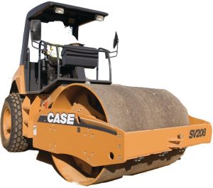
Case SV208, SV210, SV212, SV216, SV223, SV228 Factory Service & Shop Manual


Case SV208, SV210, SV212, SV216, SV223, SV228

INSTANT DOWNLOAD

Complete workshop & service manual with electrical wiring diagrams for Case SV208, SV210, SV212, SV216, SV223, SV228. It’s the same service manual used by dealers that guaranteed to be fully functional and intact without any missing page.

This Case SV208, SV210, SV212, SV216, SV223, SV228 service & repair manual (including maintenance, overhaul, disassembling & assembling, adjustment, tune-up, operation, inspecting, diagnostic & troubleshooting…) is divided into different sections. Each section covers a specific component or system with detailed illustrations. A table of contents is placed at the beginning of each section. Pages are easily found by category, and each page is expandable for great detail. The printer-ready PDF documents work like a charm on all kinds of devices.

“Cre 7-29532.pdf”
Case Vibratory Rollers SV Series (SV208, SV210, SV212, SV216, SV223, SV228) Service Manual
323 pages

“47688018.pdf”
Case SV208, SV210, SV212, SV216 Tier 3 Vibratory Rollers Service Manual
442 pages
Part number 47688018; 2nd edition English; June 2014; Replaces part number 87480985NA

EXCERPT:
SECTION 41 – STEERING – CHAPTER 1
DISASSEMBLY AND ASSEMBLY OF STEERING WHEEL
Remove the steering wheel cup (6) and the nut (21) and insert tool No. 1 under the steering wheel. Remove the steering wheel using a steering wheel spanner, dismantle the steering wheel bracket (1) and slide it with the steering rod (2) out from the steering column.
Remove the snap rings (30), (31) and press shaft (2) out together with the bearing. Remove the bearing (9) from the shaft.
Press the bearing on the shaft (the bearing must be degreased and fresh grease must be applied), secure it with the snap ring (31), press it into bracket (1), secure with the snap ring (30) and mount it to the steering column.
Check that no clearance can be detected between bracket (1) and the steering column after the shaft has been set in steering. Mount the steering wheel.

INSTANT DOWNLOAD

Posted on

Case CX800B Crawler Excavator Workshop Repair & Service Manual


Case CX800B

MCSCX800BOPES.zip
Price: $29.99 USD

Complete digital official shop manual contains service, maintenance, and troubleshooting information for the Case CX800B Tier 3 Crawler Excavator. Diagnostic and repair procedures are covered in great detail to repair, maintain, rebuild, refurbish or restore your vehicle like a professional mechanic in local service/repair workshop. This cost-effective quality manual is 100% complete and intact as should be without any missing pages. It is the same factory shop manual used by dealers that guaranteed to be fully functional to save your precious time.

This manual for Case CX800B Crawler Excavator is divided into different sections. Each section covers a specific component or system and, in addition to the standard service procedures, includes disassembling, inspecting, and assembling instructions. A table of contents is placed at the beginning of each section. Pages are easily found by category, and each page is expandable for great detail. It is in the cross-platform PDF document format so that it works like a charm on all kinds of devices. You do not need to be skilled with a computer to use the manual.

FILELIST:
84176583C – Crawler Excavator CX800B Tier 3 Service Manual.pdf
84374208 – Crawler Excavator CX800B Tier 3 Service Manual – 1 – GENERAL INFORMATION_2 – ENGINE_3 – FUEL SYSTEM.pdf
84374209 – Crawler Excavator CX800B Tier 3 Service Manual – 4 – ELECTRICAL SYSTEM (Section 4000 – 4020).pdf
84374210 – Crawler Excavator CX800B Tier 3 Service Manual – 4 – ELECTRICAL SYSTEM (Section 4021 – 4023).pdf
84374211 – Crawler Excavator CX800B Tier 3 Service Manual – 5 – UNDERCARRIAGE_6 – DRIVE TRAIN.pdf
84374212 – Crawler Excavator CX800B Tier 3 Service Manual – 8 – UPPERSTRUCTURE HYDRAULICS.pdf
84374213 – Crawler Excavator CX800B Tier 3 Service Manual – 9 – UPPERSTRUCTURE.pdf
84374214 (Replaces 84176583ANA) – Crawler Excavator CX800B Tier 3 Service Manual – Complete Contents.pdf

EXCERPT:
2 Disassembly
1 Precautions
Begin motor disassembly only after thoroughly reading the precautions below.
[1] When performing disassembly, always wear protective devices such as a helmet, goggles and safety shoes.
[2] Use the specified tools when performing disassembly.
[3] Remove all lines connected to the motor and remove the motor from the mother machine only after making sure that the machine is on a level surface and there are no external forces acting on rotating parts so that the mother machine does not operate uncontrollably when the motor is removed.
[4] To prevent foreign matter from entering the lines and motor when removing the motor from the mother machine, sufficiently clean off mud and dirt adhered around the motor before removing lines connected to the motor.
[5] When removing lines connected to the motor, hydraulic oil from inside the lines will spray out. For this reason, remove these lines only after removing pressure from inside the lines and preparing an oil pan. To prevent injuries
due to the motor falling when transporting it by lifting the motor with a liftcrane, lift the machine with the eyebolts mounted in the positions indicated in the diagram below.
[6] The motor is filled with hydraulic oil. Before disassembling the motor, prepare an oil pan and drain the hydraulic oil from the motor.
[7] To prevent injuries during disassembly, prepare a waist-high, stable work platform to perform work on.
[8] The motor comprises high-precision parts. For this reason, foreign matter adhering to parts can be damaging.
Motor disassembly should be done in an inside space without dust, and mud and dirt should be prevented from adhering to parts.
[9] The motor comprises high-precision parts. For this reason, dents and scratching on part surfaces can be damaging.
Be very careful when handling parts during disassembly and do not create any dents or scratching.
[10]To prevent personal injury and damage to parts during disassembly, do not force disassembly of parts which are especially tight to disassemble.
2 Tightening torque
The tightening torque for each fastening section are indicated in the text.
3 Travel motor disassembly procedure
Perform disassembly by observing the precautions listed in 2. (1) and following the procedure indicated below
[1] Removal of cap assemblies (2-6).
Secure the motor on top of the stable work platform, loosen the 8 hexagon socket head bolts (2-6-6) and remove the cap assemblies (2-6). Next, remove the spring seats (2-5), springs (2-4), and spring seats (2-3).
NOTICE:
The cap assemblies (2-6) are pressed out by the springs (2-4). On the other hand, if the cap assemblies
(2-6) do not come off even when the bolt is loosened, hit the cap with a plastic hammer. For this reason, observe the following precautions when working.
• Loosen the hexagon socket head bolts (2-6-6)
evenly.
• Loosen the hexagon socket head bolts (2-6-6) while pressing down the cap assemblies (2-6).
• When hitting the cap assemblies (2-6), do so with the bolts (2-6-6) only partially loosened.
If the bolts (2-6-6) are removed, there is a danger of the cap assemblies (2-6) flying out and injuring someone.