Posted on

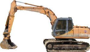
Case 9021 Hydraulic Excavator Factory Service & Shop Manual


Download Link

INSTANT DOWNLOAD (add to cart)


Case 9021 Hydraulic Excavator Factory Service & Shop Manual

675 pages, bookmarked, Searchable, Printable, high quality PDF
7-22341 – 9021 Hydraulic Excavator (9013, 9021, 9033, 9046) Service Manual.pdf

Complete workshop & service manual with electrical wiring diagrams for 9021 Hydraulic Excavator (9013, 9021, 9033, 9046). It’s the same service manual used by dealers that guaranteed to be fully functional and intact without any missing page.

This 9021 Hydraulic Excavator (9013, 9021, 9033, 9046) service & repair manual (including maintenance, overhaul, disassembling & assembling, adjustment, tune-up, operation, inspecting, diagnostic & troubleshooting…) is divided into different sections. Each section covers a specific component or system with detailed illustrations. A table of contents is placed at the beginning of each section. Pages are easily found by category, and each page is expandable for great detail. The printer-ready PDF documents work like a charm on all kinds of devices.

EXCERPT:
9021 HYDRAULIC EXCAVATOR
TABLE OF CONTENTS
1 GENERAL INFORMATION
Safety, general information and torque specifications … 1 001
Specifications … 1 002
2 ENGINE
Engine removal and installation … 2000
Engine radiator and oil cooler and cooling system reservoir … 2001
Engine specifications details .. 2402
3 FUEL SYSTEM
4 ELECTRICAL SYSTEM
Electrical schematic and troubleshooting …4001
Battery testing, maintenance and booster battery connections .. .4002
Controller .. .4003
5 STEERING
Tracks, rollers and idlers … 5002
6 POWER TRAIN
Drive motor and final drive transmission … 6002
Swing motor and swing reduction gear .. 6003
7 BRAKES
8 HYDRAULICS
Cleaning the hydraulic system .. 8000
Hydraulic schematic, troubleshooting and pressure checks .. 8001
Main hydraulic pump … 8002
Main hydraulic control valves … 8003
Cylinders … 8004
Hand control valves, foot control valves, shuttle valve, travel shuttle valve and accumulator … 8005
Eight spool solenoid valve … 8006
Cushion control valve … 8007
Auxiliary hydraulics … 8008
Hydraulic pilot filter, hydraulic inline filter and bypass oil filter .. 8011
Swing brake release solenoid valve .. 8012
Hydraulic swivel … 8013
9 MOUNTED/EQUIPMENT
Upper-structure and counterweight … 9002
Boom, arm and bucket .. 9003
Seat mounting and belts … 9004
Cab and cab equipment … 9005
Air conditioner troubleshooting … 9006
Air conditioner system service .. 9008
Air conditioner components service .. 9009
Large format hydraulic and electrical schematics .. in rear pocket
Large format hydraulic schematic (options) … in rear pocket

Disassembly
NOTE: For the disassembly and assembly operations on the 9013 machine foot control valves, refer to “Option Dozer blade – travel foot control valve” on page 40.
– Disassemble the boot (1 ).
– Remove the pin lock screw (2).
– Use a 8 mm dia. drift to remove the pin (3).
– Remove the cam (4).
– Disassemble the nuts (5) and remove the screws (6).
– Disassemble the screw (7) and remove the thrust plate (8).
– Using a special tool, drift out the bushings (9).
– Disassemble the bushings (1 0).
– Remove the guides (11) and drift out the push-rods (12).
– Disassemble the 0-rings (13) and the wiper seals (14).
– Remove the shock absorber assembly consisting of:
. the cups (15),
. the springs (16) and (17),
. the spring seats (18),
. the locking rings (19),
. the balls (20),
. the thrust bushings (21 ).
– Remove the spool assemblies:
. compress the springs (23) by pressing on the spring seats (24),
. remove the half lock-washers (25), the seats (24), the springs (22), the spring seats (26), the shims (27 and the spools (28).
– Remove the springs (22) from the foot control valve (29).
– Disassemble the plugs (30) only in the event of a leak.
– Carry out the same procedure for the second body (31 ).

Posted on

Case 9020B Excavator Factory Service & Shop Manual


Download Link

INSTANT DOWNLOAD (add to cart)


Case 9020B Excavator Factory Service & Shop Manual

1,093 pages, bookmarked, Searchable, Printable, high quality PDF
7-63062 – 9020B Excavator Service Manual.pdf

Complete workshop & service manual with electrical wiring diagrams for Case 9020B Excavator. It’s the same service manual used by dealers that guaranteed to be fully functional and intact without any missing page.

This Case 9020B Excavator service & repair manual (including maintenance, overhaul, disassembling & assembling, adjustment, tune-up, operation, inspecting, diagnostic & troubleshooting…) is divided into different sections. Each section covers a specific component or system with detailed illustrations. A table of contents is placed at the beginning of each section. Pages are easily found by category, and each page is expandable for great detail. The printer-ready PDF documents work like a charm on all kinds of devices.

EXCERPT:
TRACK
Removal
STEP 1
Park the machine on a hard level surface. Rotate the upper structure of the machine so that the cab is over the track to be removed.
STEP 2
Lower the bucket or tool to raise the machine until the track to be removed is one to two inches from the ground.
NOTE: If the machine does not have a bucket or tool installed, Install wood blocks under the arm and lower the arm onto the wood blocks. Then, lower the arm to raise the machine.
STEP 3
Master pin is identified by the hole in the center of the pin and retainer pin on opposite end.
Operate machine until master pin is near center of sprocket.
Operate machine to lower track to be removed to ground.
Rotate the upper structure of the machine so that the cab is facing the front. Stop the engine.
STEP 4
DO NOT remove the check valve. The grease in the track adjustment cylinder ls under high pressure. Loosen track as much as possible by slowly loosening the check valve to release grease pressure until the grease flows from the adjustment cylinder (approximately two turns). Grease will flow from a groove in the check valve.

Posted on

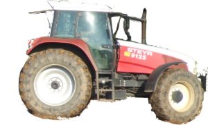
Case/Steyr 9000-Series Tractors Factory Service & Shop Manual


Download Link

INSTANT DOWNLOAD (add to cart)


Case/Steyr 9000-Series Tractors Factory Service & Shop Manual


total 3,086 pages, bookmarked, Searchable, Printable, high quality PDF

“7-96100”
Case Steyr M9078, M9086, M9094 Tractors Service – Training Manual
SVA 7-96101; 161 MB PDF
CASE / CNH / STEYR: 9105, 9115, 9125, 9145, CS68, CS75, CS78, CS78a, CS86, CS86a, CS94, CS94a, CS100, CS110, CS120, CS130, CS150, M968, M975, M9078, M9078a, M9086, M9086a, M9094, M9094a, WD320, WD420

“7-96211”
CNH Österreich 9105, 9115, 9125, 9145 Tractors Service – Training Manual
SVA 7-96212; 233 MB PDF
CASE / CNH / STEYR: 9105, 9105a, 9115, 9115a, 9125, 9125a, 9145, 9145a, CS68, CS75, CS78, CS86, CS94, CS100, CS110, CS120, CS130, CS150

Complete workshop & service manual with electrical wiring diagrams for CNH/Case Steyr olde 9000 Series Tractors. It’s the same service manual used by dealers that guaranteed to be fully functional and intact without any missing page.

This CNH/Case Steyr 9000-Series Tractors (9105, 9105a, 9115, 9115a, 9125, 9125a, 9145, 9145a, CS68, CS75, CS78, CS78a, CS86, CS86a, CS94, CS94a, CS100, CS110, CS120, CS130, CS150, M968, M975, M9078, M9078a, M9086, M9086a, M9094, M9094a, WD320, WD420) service & repair manual (including maintenance, overhaul, disassembling & assembling, adjustment, tune-up, operation, inspecting, diagnostic & troubleshooting…) is divided into different sections. Each section covers a specific component or system with detailed illustrations. A table of contents is placed at the beginning of each section. Pages are easily found by category, and each page is expandable for great detail. The printer-ready PDF documents work like a charm on all kinds of devices.

EXCERPT:
2. FLYWHEEL CASING
A. Fitting the flywheel casing
The flywheel casing is centered on the cylinder block by means of two sprung dowel pins. The flywheel casings, which are also available as a spare part, are supplied with the bore holes for the pins.
1. Clean the sealing surfaces between the cylinder block and flywheel housing.
2. Apply sealant (e.g. silicone) to the points shown in the figure.
3. Lift the flywheel casing to the correct position and insert all the bolts.
4. Centre the casing and fit the sprung dowel pins using a mandrel.
5. Tighten the inner ring bolts to a torque of 60 Nm and the outer ring bolts to a torque of 110 Nm.
B. Replacing the rear crankshaft sealing ring
1. Separate the tractor between the engine and power unit.
2. Remove the flywheel.
3. Remove the sealing ring without damaging the crankshaft.
4. Clean the sealing ring seat and grind any burr.
NOTE: If the crankshaft is worn at the sealing ring seat, a 2 mm spacer ring (spare part number 162000020718 can be fitted behind the crankshaft sealing ring.
5. Carefully press the sealing ring in down to the bottom of the flywheel casing using the 1TSW 521 and 1TSW 662 fitting tools.
NOTE: THE ASSEMBLY PROCEDURE MUST BE CARRIED OUT IN A DRY AND OIL-FREE STATE.

Posted on

Case 1850K Crawler Dozer Factory Service & Shop Manual


Download Link

INSTANT DOWNLOAD (add to cart)


1,000+ total pages, bookmarked, Searchable, Printable, high quality PDF

“6-46480.pdf”
CASE 1850K CRAWLER DOZER Service Manual
290 pages

“9-54241.pdf”
CASE 1850K (Tier 2) CRAWLER DOZER Workshop Manual
384 pages

“87630287.pdf”
CASE 1850K (Tier 3) CRAWLER DOZER Repair Manual
465 pages

Complete workshop service manual with electrical wiring diagrams for Case 1850K Crawler Dozer. It’s the same service manual used by dealers that guaranteed to be fully functional and intact without any missing page.

This 1850K service & repair manual (including maintenance, overhaul, disassembling & assembling, adjustment, tune-up, operation, inspecting, diagnostic & troubleshooting…) is divided into different sections. Each section covers a specific component or system with detailed illustrations. A table of contents is placed at the beginning of each section. Pages are easily found by category, and each page is expandable for great detail. The printer-ready PDF documents work like a charm on all kinds of devices.

EXCERPT:

FINAL DRIVES
3.1 GENERAL DESCRIPTION
The final drives are of a double reduction type, with straight spur gears and a 1 : 12.286 reduction ratio.
Specifications of final drive oil: must meet MIL-2105 or AKCELA Gear 135 HEP (SAE 80W-90).
Quantity to fill with oil final drives: 33 litres (8.7 gal.).
The 1850K final drives have two features, one of a technical type, the other service oriented.
The technical feature consists of a different arrangement of the final drives, being isolated from the stress generated by the undercarriage, which, on the other hand, is directly connected to the transmission housing, absorbing the majority of the loads on the track
chains through the hinging on the two shafts (PIVOT – SHAFTS).
The service feature consists of the reduction of the service time required to intervene on the machine,
since the modular type final drives are individually removable from the unit, without involving the transmission housing.
Final drive installed

Posted on

Case 1845 Uni-Loader Factory Service & Shop Manual


Download Link

INSTANT DOWNLOAD (add to cart)


Case 1845 Uni-Loader Factory Service & Shop Manual

666 pages, bookmarked, Searchable, Printable, high quality PDF
9-73926 – 1845 Uni-Loader Service Manual.pdf

Complete workshop & service manual with electrical wiring diagrams for Case 1845 Uni-Loader. It’s the same service manual used by dealers that guaranteed to be fully functional and intact without any missing page.

This Case 1845 Uni-Loader service & repair manual (including maintenance, overhaul, disassembling & assembling, adjustment, tune-up, operation, inspecting, diagnostic & troubleshooting…) is divided into different sections. Each section covers a specific component or system with detailed illustrations. A table of contents is placed at the beginning of each section. Pages are easily found by category, and each page is expandable for great detail. The printer-ready PDF documents work like a charm on all kinds of devices.

EXCERPT:
ENGINE REMOVAL
1. Drain cooling system.
2. Remove radiator and oil cooler assembly as instructed in Section 2054.
3. On diesel engine, disconnect or remove from the left side of the engine:
a. Battery and engine ground cables from starter mounting bolt. Tape end of battery ground cable to prevent accidental grounding.
b. Battery cable and wiring from starter solenoid.
c. Wire from engine temperature sender.
d. Wiring from alternator. Then make sure wiring harness is free of engine and place out of way.
e. Hose between air cleaner and intake manifold.
4. On diesel engine, disconnect or remove from right hand side of engine:
a. Throttle rod and fuel shutoff cable at the injection pump. Remove throttle rod from cross-shaft, and shutoff cable clamp from engine block and place cable out of way.
b. Fuel supply line at fuel filter and return line from the No. 4 injector.
Plug hoses to prevent fuel tank from draining.
c. Wire from engine oil pressure sender.
5. On gas engine, disconnect or remove from left side of engine:
a. Fuel line at fuel pump. Remove hose and clamp and plug hose to prevent fuel tank from draining.
b. Battery and engine ground cables from starter mounting bolt. Tape end of battery ground to prevent accidental grounding.
c. Battery cable and wiring from starter solenoid.
d. Throttle rod at linkage on engine block.
e. Wiring from engine temperature sender, ignition coil and alternator.
Make sure wiring harness is free of engine and place out of way.
6. On gas engine, disconnect or remove from right hand side of engine:
a. Choke cable at carburetor. Remove cable from clamp and place cable out of way.
b. Wire from engine oil pressure sender.
c. Hose between carburetor and air cleaner.
7. Remove muffler and hydraulic system oil filter housing.
8. Remove the flywheel guard and remove the drive coupling to flywheel cap screws and flat washers.
9. Remove cotter pins from the front and rear engine mounting bolts and remove nuts, flat washers and bolts.
10. Attach lifting sling to engine and lifting device to sling.
11. Carefully remove engine from rear of machine.