Posted on

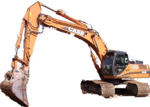
Case CX460 Crawler Excavator Workshop Repair & Service Manual


Download Link

INSTANT DOWNLOAD (add to cart)


2,804 pages, bookmarked, Searchable, Printable, high quality PDF
7-27691EN – CX460 Tier 3 Crawler Excavator Service Manual (EN).pdf
9-36500 – EXCAVADORA SOBRE ORUGAS CX460 SCHEMATIC SET (ES).pdf
9-36510 – ESCAVATORE CINGOLATO CX460 SCHEMATIC SET (IT).pdf
9-43830 – Pelles sur Chenilles CX460 MANUEL DE SERVICE (FR).pdf
9-43840 – CX460 Crawler Excavators Service Manual (EN).pdf
9-43850 – CX460 RAUPENBAGGER REPARATUR HANDBUCH (DE).pdf

Complete digital official shop manual contains service, maintenance, and troubleshooting information for the Case CX460 Crawler Excavator. Diagnostic and repair procedures are covered in great detail to repair, maintain, rebuild, refurbish or restore your Case CX460 like a professional mechanic in local service/repair workshop. This cost-effective quality manual is 100% complete and intact as should be without any missing pages. It is the same factory shop manual used by dealers that guaranteed to be fully functional to save your precious time.

This manual for Case CX460 Crawler Excavator is divided into different sections. Each section covers a specific component or system and, in addition to the standard service procedures, includes disassembling, inspecting, and assembling instructions. A table of contents is placed at the beginning of each section. Pages are easily found by category, and each page is expandable for great detail. It is in the cross-platform PDF document format so that it works like a charm on all kinds of devices. You do not need to be skilled with a computer to use the manual.

EXCERPT:
CX460 TIER 3 CRAWLER EXCAVATOR
SERVICE MANUAL
TABLE OF CONTENTS
DIVISION/SECTION SECTION N° REFERENCE N°
1 GENERAL INFORMATION
Safety, general information and standard torque data ..1001 7-27691EN
General specifications and special torque setting ….1002 SC4601002-0EN
2 ENGINE
Radiator and oil-cooler …2001 SM4602001-0EN
Engine specifications….*
Disassembly and assembly of the engine ….*
3 FUEL SYSTEM
Fuel tank…3001 SM4603001-0EN
Fuel engine system ..*
4 ELECTRICAL SYSTEM
Electrical system, electrical and electronic troubleshooting …4001 SC4604001-0EN
Main and engine electronic control boxes …4003 SM4604003-0EN
5 UNDERCARRIAGE
Removal and installation of tracks …5001 SM160B5001-0EN
Rollers ..5003 SM4605003-0EN
Sprocket….5004 SM160B5004-0EN
Idler wheel and tension shock absorber …5005 SM4605005-0EN
6 DRIVE TRAIN
Drive motor and final drive transmission removal and installation…6001 SM4606001-0EN
Swing reduction gear, removal and installation ..6003 SM4606003-0EN
Swing reduction gear, disassembly and assembly …6004 SM4606004-0EN
Travel reduction gear disassembly and assembly …6005 SM4606005-0EN
7 UNDERCARRIAGE HYDRAULICS
8 UPPERSTRUCTURE HYDRAULICS
Depressurizing and decontaminating the hydraulic system, use of the
vacuum pump and bleeding the components….8000 SM4608000-0EN
Specifications, troubleshooting, checks and hydraulic pressure settings ..8001 SC4608001-0EN
Hydraulic reservoir removal and installation …8002 SM4608002-0EN
Main and hydraulic pilot pumps, removal and installation ….8003 SM4608003-0EN
Main hydraulic control valve, removal and installation ….8004 SM4608004-0EN
Attachment cylinders, removal and installation ..8005 SM4608005-0EN
Hydraulic swivel, removal and installation …8006 SM4608006-0EN
Pilot blocs, removal and installation….8007 SM4608007-0EN
Swing motor, removal and installation …8008 SM4608008-0EN
Main hydraulic pump, disassembly and assembly ….8010 SM4608010-0EN
Main hydraulic control valve, disassembly and assembly…8011 SM4608011-0EN
Attachment cylinders, disassembly and assembly …8012 SM4608012-0EN
Hand control levers, disassembly and assembly …8013 SM4608013-0EN
Foot control levers, disassembly and assembly..8014 SM4608014-0EN
Six-solenoid valves, disassembly and assembly …8015 SM4608015-0EN
Caution valve, disassembly and assembly …8016 SM4608016-0EN
Safety valves…8017 SM4608017-0EN
Hydraulic swivel, disassembly and assembly ..8018 SM4608018-0EN
Swing motor, disassembly and assembly ….8019 SM4608019-0EN
Hydraulic functions …8020 SC4608020-0EN
Travel hydraulic motor, disassembly and assembly …8021 SM4608021-0EN
Fan motor, removal and installation….8022 SM4608022-0EN
Fan motor, disassembly and assembly..8023 SM4608023-0EN
Fan pump, removal, disassembly, assembly and installation..8024 SM4608024-0EN
Hydraulic component functions….8030 SC4608030-0EN
9 UPPERSTRUCTURE
Upperstructure, turntable and counterweight.. 9002 SM4609002-0EN
Boom, dipper and bucket .. 9003 SM4609003-0EN
Seat, removal and installation.. 9004 SM4609004-0EN
Cab and cab equipment…. 9005 SM4609005-0EN
Air conditioning unit disassembly and assembly… 9007 SM4609007-0EN
Large size hydraulic schematics ..Pocket 87574463A
Large size electrical schematics ..Pocket 87574470A

MAIN HYDRAULIC PUMP
Removal and installation
STEP 1
Park the machine on hard, flat ground. Lower the attachment to the ground.
STEP 2
Release pressure in the hydraulic system and in the hydraulic reservoir (see Section 8000).
STEP 3
Disconnect the battery ground (-) cable (1) from the battery.
STEP 4
Remove the access panel (1) below the hydraulic reservoir.
STEP 5
Put an appropriate container under the hydraulic reservoir. Open the drain cock and drain the hydraulic fluid. Close the cock.
STEP 6
Remove the engine hood (1) then the protective grille (2).
STEP 7
Disconnect all the hoses from the quick coupling control block (A). Remove the block (A) from the panel (B).
STEP 8
Remove all the retaining screws (A) from the panel (B), then remove the panel (B).
STEP 9
Remove the circlip (1) fastening the silencer pipe to the turbocharger.
NOTE: All the engine and the exhaust system to cool down before starting any disassembly.
STEP 10
Remove the four retaining nuts from the silencer circlips, then remove the two circlips.
NOTE: When installing, tighten the nuts to the torque specified on page 3.
STEP 11
Remove the silencer assembly (1) from the machine.
STEP 12
Remove the three retaining screws (1) from the silencer bracket, then remove the silencer bracket.
NOTE: When installing, tighten the screws to the torque specified on page 3.
STEP 13
To facilitate proper installation, attach identification tags to all hoses and electrical connections of the main hydraulic pump and the pilot pump.
STEP 14
Remove the pipes, the hydraulic hoses and the electrical connections. Seal all hoses and unions of the main pump as well as those of the pilot pump.
STEP 15
Install an appropriate lifting apparatus on the hydraulic pump. Do not leave any slack so that the pump can be supported once the fastening screws of the pump are removed.
STEP 16
Remove the retaining screws of the hydraulic pump.
NOTE: When installing, tighten the screws to the torque specified on page 3.
STEP 17
Remove the hydraulic pump from the motor and put it away from the machine. Place the hydraulic pump on a clean workbench using suitable brackets.
NOTE: Carry out the following step only if a new hydraulic pump needs to be installed.
STEP 18
Remove the connections of the hydraulic pump that has just been removed and install them on the new hydraulic pump. Remove and install the connections one after another to avoid improper installation of the connections on the new hydraulic pump.
NOTE: For installing the hydraulic pump, proceed in the reverse order to that of removal. Replace all rings with new rings.
STEP 19
Remove the four screws and washers (1). Remove the cover (2) and the O-ring from on top of the hydraulic reservoir. Scrap the O-ring. Fill the hydraulic reservoir with hydraulic fluid (see Section 1002) up to a level in between the “high” and “low” marks on the visual gauge. Install the cover with a new O-ring, fasten it using four screws and washers (1).
Connect the ground (-) cable (1) of the battery.
STEP 20
NOTE: Always drain the air out from the hydraulic pump before starting the engine. If the air has not been drained out, the pump can get damaged. For the procedure, see Section 8000.
NOTE: Before carrying out any work with the machine, operate the swing, travel and the attachment for five minutes with the engine at idle speed. Check that there are no leaks in the system, check the oil level in the hydraulic reservoir. Top up if necessary, refer to Section 8001.

Posted on

Case CX350D, CX370D Crawler Excavator Factory Service & Shop Manual


Download Link

INSTANT DOWNLOAD (add to cart)


3,358 pages, bookmarked, Searchable, Printable, high quality PDF
47843027 – CX350D, CX370D Crawler Excavator Service Manual.pdf
CX350D Crawler excavators LC version (TIER4 FINAL) – EU Market
CX350D Crawler excavators NLC version (TIER4 FINAL) – EU Market
CX370D Crawler excavators LC version (TIER4 FINAL) – EU Market
CX370D Crawler excavators NLC version (TIER4 FINAL) – EU Market

Complete workshop & service manual with electrical wiring diagrams for Case CX350D, CX370D Crawler Excavator. It’s the same service manual used by dealers that guaranteed to be fully functional and intact without any missing page.

This Case CX350D, CX370D Crawler Excavator service & repair manual (including maintenance, overhaul, disassembling & assembling, adjustment, tune-up, operation, inspecting, diagnostic & troubleshooting…) is divided into different sections. Each section covers a specific component or system with detailed illustrations. A table of contents is placed at the beginning of each section. Pages are easily found by category, and each page is expandable for great detail. The printer-ready PDF documents work like a charm on all kinds of devices.

EXCERPT:
CONTENTS
INTRODUCTION
Engine… 10
[10.001] Engine and crankcase . . .10.1
[10.102] Pan and covers . . .. . 10.2
[10.106] Valve drive and gears . . .. 10.3
[10.101] Cylinder heads . . .. . . 10.4
[10.105] Connecting rods and pistons. . .. 10.5
[10.103] Crankshaft and flywheel. . . . . 10.6
[10.216] Fuel tanks . . .. 10.7
[10.206] Fuel filters . . .. 10.8
[10.218] Fuel injection system. . . 10.9
[10.202] Air cleaners and lines . . . . . 10.10
[10.250] Turbocharger and lines. . . . 10.11
[10.254] Intake and exhaust manifolds and muffler . . . 10.12
[10.500] Selective Catalytic Reduction (SCR) exhaust treatment . . .10.13
[10.501] Exhaust Gas Recirculation (EGR) – Diesel Particulate Filter (DPF) exhaust
treatment . . . 10.14
[10.400] Engine cooling system . . . . 10.15
[10.414] Fan and drive . . .. . 10.16
[10.310] Aftercooler. . . . . 10.17
[10.304] Engine lubrication system . . .. . 10.18
Hydraulic systems… 35
[35.000] Hydraulic systems. . .35.1
[35.300] Reservoir, cooler, and filters. . .. . 35.2
[35.106] Variable displacement pump . . .. 35.3
[35.102] Pump control valves. . . . 35.4
[35.304] Combination pump units . . . . 35.5
[35.359] Main control valve . . .35.6
[35.357] Pilot system . . . . . 35.7
[35.355] Hydraulic hand control . . .35.8
[35.356] Hydraulic foot control. . . 35.9
[35.352] Hydraulic swing system . . . 35.10
[35.353] Hydraulic travel system . . . 35.11
[35.354] Hydraulic central joint . . . . . 35.12
[35.736] Boom hydraulic system . . . 35.13
[35.737] Dipper hydraulic system. . . 35.14
[35.738] Excavator and backhoe bucket hydraulic system . . .. . 35.15
[35.360] Hammer and rotating bucket hydraulic system . . . 35.16
Frames and ballasting … 39
[39.140] Ballasts and supports . . .. 39.1
Tracks and track suspension …. 48
[48.130] Track frame and driving wheels . . . . 48.1
[48.100] Tracks . . .48.2
[48.134] Track tension units . . . . . 48.3
[48.138] Track rollers . . . . . 48.4
Cab climate control … 50
[50.100] Heating . . . . . 50.1
[50.200] Air conditioning. . .. . . 50.2
Electrical systems … 55
[55.000] Electrical system . . .. 55.1
[55.100] Harnesses and connectors. . .. . . 55.2
[55.525] Cab engine controls . . . . 55.3
[55.015] Engine control system. . .. 55.4
[55.201] Engine starting system . . .55.5
[55.301] Alternator. . . 55.6
[55.302] Battery. . .55.7
[55.202] Cold start aid . . . . 55.8
[55.011] Fuel tank system . . .. 55.9
[55.010] Fuel injection system. . .55.10
[55.014] Engine intake and exhaust system. . . . 55.11
[55.988] Selective Catalytic Reduction (SCR) electrical system . . .. 55.12
[55.989] Exhaust Gas Recirculation (EGR) electrical system . . . . . 55.13
[55.012] Engine cooling system . . . . 55.14
[55.013] Engine oil system . . . . 55.15
[55.640] Electronic modules . . . 55.16
[55.512] Cab controls. . . 55.17
[55.036] Hydraulic system control . . .. . . 55.18
[55.051] Cab Heating, Ventilation, and Air-Conditioning (HVAC) controls. . . . . 55.19
[55.050] Heating, Ventilation, and Air-Conditioning (HVAC) control system. . . 55.20
[55.524] Cab controls (Lift arm, Boom, Dipper, Bucket) . . . . 55.21
[55.416] Swing control system . . . . . 55.22
[55.417] Travel control system . . . . . 55.23
[55.530] Camera. . . 55.24
[55.518] Wiper and washer system. . .. . 55.25
[55.404] External lighting . . .55.26
[55.514] Cab lighting . . . 55.27
[55.408] Warning indicators, alarms, and instruments . . . . . 55.28
[55.992] Anti-theft system . . . . . 55.29
[55.DTC] FAULT CODES. . .55.30
Booms, dippers, and buckets … 84
[84.910] Boom . . .. 84.1
[84.912] Dipper arm . . .84.2
[84.100] Bucket . . .84.3
Platform, cab, bodywork, and decals … 90
[90.150] Cab. . .. . . 90.1
[90.156] Cab glazing . . . . . 90.2
[90.118] Protections and footboards. . .. . . 90.3
[90.120] Mechanically-adjusted operator seat. . . . 90.4
[90.100] Engine hood and panels . . . . 90.5

Hydraulic systems – Boom hydraulic system
Boom cylinder – Prepare – For disassemble
Preparations prepare the following before starting disassembly.
1. Work platform preparation
Prepare a sufficiently spacious, solid and stable work surface so that parts will not fall or move during work.
2. Tool and materials preparation
Prepare the tools and materials shown on the following pages.
General work precautions
1. Thoroughly clean any dirt or mud from the outside walls of the cylinder before starting disassembly.
2. Each part has been manufactured with a high degree of precision, so be careful to not let parts bump each other or fall when handling them.
3. If parts are struck or pried off with excessive force during work because they are tight, this may cause burrs or damage which causing reduction in performance or oil leaking. Perform work carefully and thoroughly.
4. If a cylinder is left disassembled, humidity and dirt can cause rust on parts. If a pause in the work is unavoidable, be careful to prevent rust and keep off dust.
Maintenance standards
Replace sliding parts and seal parts as follows.
1. Bushing
When 1/4 of the circumference is worn brown over the entire length.
2. Seals and slide rings
Replace with new parts when the cylinder is disassembled.
3. Pin bushing
When there is severe seizing.
4. Piston rod
When the piston rod is bent 0.5 mm (0.0197 in) / 1 m (3.281 ft) or more.

Posted on

Case Construction Crawlers/Loaders/Tractors/Excavators Operator’s Manuals


Download Link

INSTANT DOWNLOAD (add to cart)


Case Construction Crawlers/Loaders/Tractors/Excavators Operator’s Manuals

12,000+ pages, bookmarked, Searchable, Printable, high quality PDF

Operator’s Manuals for Case Construction Crawlers/Loaders/Tractors/Excavators. It’s the same service manual used by dealers that guaranteed to be fully functional and intact without any missing page.

These manuals are divided into different sections. Each section covers a specific component or system with detailed illustrations. A table of contents is placed at the beginning of each section. Pages are easily found by category, and each page is expandable for great detail. The printer-ready PDF documents work like a charm on all kinds of devices.

FILE LIST:
40 Crawler Series D Operators Manual.pdf
40 Crawler Series E Operators Manual.pdf
50 Crawler Series D Operators Manual.pdf
50 Crawler Series E Operators Manual.pdf
60, 75, 90, 115, 160 Series Hydraulic Excavators Operators Manual.pdf
170C Series Excavators Operators Manual.pdf
310 Crawler Operators Manual.pdf
320 CKS Poclain Operators Manual.pdf
320 Wheel Tractor Operators Manual.pdf
350B Crawler Tractor Operators Manual.pdf
420B Gasoline Crawler Operators Manual.pdf
430 Wheel Fork Lift Operators Manual.pdf
450 Crawler Operators Manual.pdf
450B_455B Crawler Operators Manual.pdf
480B Loader Backhoe Operators Manual.pdf
480E Loader Backhoe, 480E LL Loader Landscaper Operators Manual.pdf
530 Construction King Fork Lift Operators Manual.pdf
550 CK Forklift Operators Manual.pdf
550 Crawler Operators Manual.pdf
550G Crawler Operators Manual.pdf
550H Crawler Operators Manual.pdf
580 Series Construction King Wheel Tractors Diesel Operators Manual.pdf
580 Super K, 580SK Turbo Loader Backhoe Operators Manual.pdf
580F Construction King Loader Backhoe Operators Manual.pdf
580G Loader Backhoe Operators Manual.pdf
580L, 580L turbo, 580 Super L, 590 Super L Series Loader Backhoes Operators Manual.pdf
580M, 580 Turbo, 580SM, 580SM+, 590SM Series 2 Loader Backhoe Operators Manual.pdf
580M, 580SM, 580SM+, 590SM, 590SM+ Series 3 Loader Backhoe Operators Manual.pdf
580N, 580SN-WT, 580SN, 590SN Loader Backhoe Operators Manual.pdf
580N, 580SN, 580SN WT, 590SN Tier4 Tractor Loader Backhoe Operators Manual.pdf
584_585_585 Power Shuttler Forklift Operators Manual.pdf
584_585_586 Hydrostatic Drive Forklift Operators Manual.pdf
584C_585C_586C Forklift Operators Manual.pdf
584D_585D_586D Forklift Operators Manual.pdf
584E_585E_586E Forklift Operators Manual.pdf
585G, 586G, 588G Forklift Operators Manual.pdf
586G, 588G Series 3_Tier 3 Forklift Operators Manual.pdf
586H, 588H Tier 4 Operators Manual.pdf
590 Turbo Loader Backhoe Operators Manual.pdf
650H Crawler Operators Manual.pdf
650K 750K 850K Op’s Manual.pdf
650K 750K 850K Series 2 Op’s Manual.pdf
650L Tier3 Crawler Dozer Operators Manual.pdf
680CK Series C Loader Backhoe Operators Manual.pdf
680G Loader Backhoe Operators Manual.pdf
680K Loader Backhoe Operators Manual.pdf
680L Loader Backhoe Operators Manual.pdf
750 Industrial Diesel Crawler Operators Manual.pdf
750H Crawler Operators Manual.pdf
750L, 850L Crawler Dozer Operators Manual.pdf
780 CK Loader Backhoe Operators Manual.pdf
780C Loader Backhoe Operators Manual.pdf
845B, 865B, 885B Grader Operator’s Manual.pdf
850 Crawler Operators Manual.pdf
850D, 855D Crawler Operators Manual.pdf
850H Crawler Operators Manual.pdf
880 Excavator Operators Manual.pdf
880C Excavator Operators Manual.pdf
980 Excavator Operators Manual.pdf
980B Excavator Operators Manual.pdf
1000CK Excavator Operators Manual.pdf
1080B Excavator Operators Manual.pdf
1088 Long Track Excavator Operators Manual.pdf
1150D, 1155D Crawlers Operators Manual.pdf
1150E, 1155E Dozer Operators Manual.pdf
1150G Crawler Operators Manual.pdf
1150H Crawler Operators Manual.pdf
1150K Series 3 Crawler Dozer Operators Manual.pdf
1280B Excavator Operators Manual.pdf
1450 Crawler Loader Operators Manual.pdf
1450 Dozer Operators Manual.pdf
1550 Crawler Operators Manual.pdf
1650K (Series 2 Engine) Crawler Dozer Operators Manual.pdf
1650L Crawler Dozer Operators Manual.pdf
1850K Crawler Dozer Operators Manual.pdf
1850K Series 2 Crawler Dozer Operators Manual.pdf
1850K Series 3 Crawler Dozer Operators Manual.pdf
9010 Excavator Operators Manual.pdf
9010B Excavator Operators Manual.pdf
9020 Excavator Operators Manual.pdf
9030 Excavator Operators Manual.pdf
9030B Excavator Operators Manual.pdf
9040 Excavator Operators Manual.pdf
9040B Excavator Operators Manual.pdf
9045B Excavator Operators Manual.pdf
9050B Excavator Operators Manual.pdf
9060 Excavator Operators Manual.pdf
CX14 Mini-Excavator Operators Manual.pdf
CX17B Excavators Operators Manual.pdf
CX17B Tier 4 Hydraulic Excavator Operators Manual.pdf
CX27B Excavator Operators Manual.pdf
CX27B Tier 4 Compact Crawler Excavator Operators Manual.pdf
CX31B – CX36B Excavators Operators Manual.pdf
CX31B Tier 4 Compact Crawler Excavator Operators Manual.pdf
CX36B Tier 4 Compact Crawler Excavator Operators Manual.pdf
CX47 Mini-Excavator Operators Manual.pdf
CX50B Tier 4 Compact Crawler Excavator Operators Manual.pdf
CX55B Tier 4 Compact Crawler Excavator Operators Manual.pdf
CX75SR Tier 3 Hydraulic Excavator Operators Manual.pdf
CX80 Tier 3 Excavator Operators Manual.pdf
CX130, CX160 Excavator Operators Manual.pdf
CX130B Tier 3 Crawler Excavator Operators Manual.pdf
CX130C Tier 4 Crawler Excavator Operators Manual.pdf
CX135SR Excavator Operators Manual.pdf
CX145CSR Tier 4 Crawler Excavator Operators Manual.pdf
CX160C Tier 4 Crawler Excavator Operators Manual.pdf
CX210, CX240 Excavator Operators Manual.pdf
CX210B Tier 3 Crawler Excavator Operators Manual.pdf
CX210C Tier 4 Crawler Excavator Operators Manual.pdf
CX210C Tier4 Operators Manual.pdf
CX225B Excavator Operators Manual.pdf
CX225SR Excavator Operators Manual.pdf
CX290 Excavator Operators Manual.pdf
CX290B Excavator Operators Manual.pdf
CX300C Tier 4 Crawler Excavator Operators Manual.pdf
CX330 Excavator Operators Manual.pdf
CX330B Excavator Operators Manual.pdf
CX350B Tier 3 Excavator Operators Manual.pdf
CX350C Tier 4 Crawler Excavator Operators Manual.pdf
CX460 Excavator Operators Manual.pdf
CX470B Hydraulic Excavator Operators Manual.pdf
CX700 Tier III Hydraulic Excavator Operators Manual.pdf
CX700B Tier 3 Excavator Operators Manual.pdf
CX800B Tier 3 Crawler Excavator Operators Manual.pdf
L Series Loader Backhoe Operators Manual.pdf
New Holland T6010, T6020, T6030, T6050, T6070 Delta & Plus Tractors Operators Manual.pdf
New Holland T6020, T6040, T6060 Elite Tractors Operators Manual.pdf
New Holland T7030, T7040, T7050, T7060 Operators Manual.pdf
SR130-SR200-SR150-SR220-SR175-SR250-SV185-SV250-SV300 Alpha Series Skid Steer Loader & TR270-TR320-TV380 Compact Track Loader Operators Manual.pdf
SR220, SR250, SV250, SV300, TR320, TV380 Operators Manual.pdf
W24 Articulated Loader Operators Manual.pdf

Posted on

Case Crawler Excavator CX330, CX350 Factory Service & Shop Manual


Download Link

INSTANT DOWNLOAD (add to cart)


2,418+ pages, bookmarked, Searchable, Printable, high quality PDF
9-42830 – EXCAVADORA SOBRE ORUGAS CX330 – CX350 SCHEMATIC SET (ES).pdf
9-42840 – ESCAVATORE CINGOLATO CX330 – CX350 SCHEMATIC SET (IT).pdf
9-42880 – Pelles sur Chenilles CX330 et CX350 MANUEL DE SERVICE (FR).pdf
9-42890 – CX330 and CX350 Crawler Excavators Service Manual (EN).pdf
9-42900 – CX330 und CX350 RAUPENBAGGER REPARATUR HANDBUCH (DE).pdf
84355068 – Case CX350B Tier 3 Crawler Excavator Service Manual (4 – Electrical System, Section 4000 – 4020).pdf

Complete workshop & service manual with electrical wiring diagrams for Case Crawler Excavator CX330, CX350. It’s the same service manual used by dealers that guaranteed to be fully functional and intact without any missing page.

This Case Crawler Excavator CX330, CX350 service & repair manual (including maintenance, overhaul, disassembling & assembling, adjustment, tune-up, operation, inspecting, diagnostic & troubleshooting…) is divided into different sections. Each section covers a specific component or system with detailed illustrations. A table of contents is placed at the beginning of each section. Pages are easily found by category, and each page is expandable for great detail. The printer-ready PDF documents work like a charm on all kinds of devices.

Posted on

Case Crawler Excavator CX330 Factory Service & Shop Manual


Download Link

INSTANT DOWNLOAD (add to cart)


DIGITAL CAMERA

1,100+ pages, bookmarked, Searchable, Printable, high quality PDF
7-88631 – 24 Valve, 8.3 Liter Engine Service Manual.pdf – 496 pages
87565293 NA – Crawler Excavator CX330 Tier III Service Manual.pdf – 672 pages

Complete workshop & service manual with electrical wiring diagrams for Case Crawler Excavator CX330. It’s the same service manual used by dealers that guaranteed to be fully functional and intact without any missing page.

This Case Crawler Excavator CX330 service & repair manual (including maintenance, overhaul, disassembling & assembling, adjustment, tune-up, operation, inspecting, diagnostic & troubleshooting…) is divided into different sections. Each section covers a specific component or system with detailed illustrations. A table of contents is placed at the beginning of each section. Pages are easily found by category, and each page is expandable for great detail. The printer-ready PDF documents work like a charm on all kinds of devices.

EXCERPT:
TABLE OF CONTENTS
1 GENERAL INFORMATION
Safety, general information and standard torque data ..1001 7-27691NA
General specifications and special torque setting..1002 9-94170NA
Numerical value conversion table ..1003 9-35540
2 ENGINE
Radiator and engine, removal and installation ..2001 9-94830NA
Engine specifications .. *
Disassembly and assembly of the engine.. *
3 FUEL SYSTEM
Fuel tank ..3001 9-43471NA
Fuel engine system.. *
4 ELECTRICAL SYSTEM
Electrical system, electrical and electronic troubleshooting..4001 9-94180NA
Inspection and maintenance of batteries and connecting a booster battery..4002 9-43460NA
Main and engine electronic control boxes..4003 9-43451NA
5 UNDERCARRIAGE
Removal and installation of tracks ..5001 9-42910NA
Rollers..5003 9-42921NA
Sprocket ..5004 9-36890NA
Idler wheel and tension shock absorber ..5005 9-94790NA
6 DRIVE TRAIN
Drive motor and final drive transmission removal and installation ..6001 9-43141NA
Swing reduction gear, removal and installation..6003 9-43210NA
Swing reduction gear, disassembly and assembly..6004 9-43221NA
Travel reduction gear disassembly and assembly ..6005 9-43151NA
7 UNDERCARRIAGE HYDRAULICS
8 UPPERSTRUCTURE HYDRAULICS
Depressurising and decontaminating the hydraulic system, use of the
vacuum pump and bleeding the components ..8000 9-43501NA
Specifications, troubleshooting, checks and hydraulic pressure settings..8001 9-94190NA
Hydraulic reservoir removal and installation ..8002 9-43230NA
Main and pilot pumps, removal and installation ..8003 9-94840NA
Main hydraulic control valve, removal and installation ..8004 9-43261NA
Attachment cylinders, removal and installation ..8005 9-43251NA
Hydraulic swivel, removal and installation..8006 9-43390NA
Pilot blocs, removal and installation ..8007 9-43400NA
Swing motor, removal and installation..8008 9-43200NA
Main hydraulic pump, disassembly and assembly ..8010 9-94850NA
Main hydraulic control valve, disassembly and assembly ..8011 9-43551NA
Attachment cylinders, disassembly and assembly ..8012 9-94760NA
Hand control levers, disassembly and assembly ..8013 9-94630NA
Foot control levers, disassembly and assembly ..8014 7-28301NA
Six-solenoid valves, disassembly and assembly..8015 9-43361NA
Caution valve, disassembly and assembly..8016 9-94770NA
Hydraulic swivel, disassembly and assembly..8018 9-43190NA
Swing motor, disassembly and assembly ..8019 9-43441NA
Hydraulic functions..8020 9-94200NA
Travel hydraulic motor, disassembly and assembly..8021 9-43161NA
Hydraulic component functions..8030 9-94210NA
9 UPPERSTRUCTURE
Upperstructure, turntable and counterweight..9002 9-43411NA
Boom, dipper and bucket ..9003 9-43421NA
Seat and seat belt ..9004 9-40960NA
Cab and cab equipment..9005 9-94800NA
Air conditioning troubleshooting..9006 7-xxxxxFR
Air conditioning unit disassembly and assembly..9007 9-94640NA
Air conditioning servicing ..9008 7-xxxxxFR
Air conditioning components..9009 7-xxxxxFR
Large format hydraulic schematic ..Pocket 9-94040
Large format electrical schematic ..Pocket 9-94050
..
INSPECTING THE BATTERY
NOTE: For a proper inspection of the battery, carry out each part of the inspection until the actual state of the battery is known.
Visual inspection
– Check that the cable connections are clean and tightened properly. Remove all foreign bodies from the top of the battery.
– Check the box, the terminals and the battery cables for damage.
– Check the electrolyte level, see page 4.
– If you have added water to the battery, charge the battery for 15 minutes at 15 to 25 amperes to allow the water to mix correctly with the electrolyte.
Check the specific gravity
Use a battery hydrometer to check the specific gravity of the electrolyte. The specific gravity indicates the charge level in each cell.
Battery hydrometers are designed to indicate the correct specific gravity when the electrolyte is at a temperature of 26.7°C.
Before checking the specific gravity, check the electrolyte temperature. If the hydrometer is not equipped with a thermometer, use a thermometer to measure the electrolyte temperature. The thermometer has to be calibrated at least up to 52°C.
1. Remove sufficient electrolyte from a cell so that the float moves freely in the tube.
NOTE: If it is not possible to check the specific gravity without first adding water to the cell, charge the battery for 15 minutes at 15 to 25 amperes to allow the water to mix correctly with the electrolyte. Then, check the specific gravity.
2. Read the float.
3. Read the thermometer, if the reading is greater than 26.7°C, add specific gravity points to the reading to get the specific gravity. If the reading is less than 26.7°C, deduct specific gravity points from the reading to get the specific gravity. See the illustration below and add or deduct specific gravity points depending on the situation.
4. Record the corrected specific gravity for each cell.
5. If the difference between the high and low readings is 0.050 minimum, charge the battery and check the specific gravity again. If after charging the difference is still 0.050 minimum, install a new battery.
NOTE: When the battery is replaced, do not use a used battery with a new one. The life of the new battery will be reduced.
..