Posted on

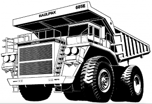
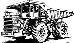
Komatsu 685E Dump Truck Factory Shop & Service Manual

Pages from DG667 – Dump Truck 685E Shop Manual

MKMTS685EOPES.PDF
Price: $29.99 USD

Complete workshop & service manual with electrical wiring diagrams for Komatsu 685E Dump Truck. It’s the same service manual used by dealers that guaranteed to be fully functional and intact without any missing page.

This Komatsu 685E Dump Truck service & repair manual (including maintenance, overhaul, disassembling & assembling, adjustment, tune-up, operation, inspecting, diagnostic & troubleshooting…) is divided into different sections. Each section covers a specific component or system with detailed illustrations. A table of contents is placed at the beginning of each section. Pages are easily found by category, and each page is expandable for great detail. The printer-ready PDF documents work like a charm on all kinds of devices.

DG667 – Dump Truck 685E Shop Manual.pdf
DG674 – Dump Truck 685E Operator handbook.pdf

EXCERPT:
TABLE OF CONTENTS
SUBJ ECT . . . . . . SECTION
GENERAL INFORMATION . . . . . . A
STRUCTURES . . . . . B
ENGINE, FUEL, COOLING AND AIR CLEANER . . . . . . C
ELECTRIC SYSTEM (2 4 VDC. NON-PROPULSION) . . . . D
ELECTRIC PROPULSION AND CONTROL . . . . . . E
DRIVE AXLE, SPINDLES AND WHEELS . . . . . . G
HYDRAIR® II SUSPENSIONS . . . . H
BRAKE CIRCUIT . . . . J
AIR SYSTEM . . . . . . K
HYDRAULIC SYSTEM . . . . . L
OPTIONS AND SPECIAL TOOLS . . . . . . M
OPERATOR’S CAB . . . . . N
LUBRICATION AND SERVICE . . . . P
ALPHABETICAL INDEX . . . Q
SYSTEM SCHEMATICS . . . . R

ENGINE COMPONENTS
THROTTLE CONTROL AIR CYLINDERS
the throttle control cylinder(s) controls the engine RPM. the cylinder is controlled by the operator’s throttle treadle valve. Various system components and the position of the engine idle switch can affect the RPM rang e available to the operator.
On Detroit Diesel engines, one cylinder provides the full rang e of engine RPM (750 to 2040 RPM) and also is designed to provide a mid range engine speed (1675 RPM) required while operating the dynamic retarding system.
On engines, two cylinders are required. the inboard cylinder provides full rang RPM (750 to 2300 RPM), the outboard cylinder controls the dynamic retarding RPM (1675 RPM).
Detroit Diesel Engine
Throttle Cylinder Removal

Posted on

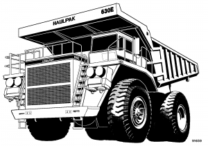
Komatsu 630E Dump Truck Factory Shop & Service Manual

Komatsu 630E Dump Truck

MKMTS630EOPES.PDF
Price: $29.99 USD

Complete workshop & service manual with electrical wiring diagrams for Komatsu 630E Dump Truck. It’s the same service manual used by dealers that guaranteed to be fully functional and intact without any missing page.

This service & repair manual for KOMATSU 630E HAULPAK TRUCK (including maintenance, overhaul, disassembling & assembling, adjustment, tune-up, operation, inspecting, diagnostic & troubleshooting…) is divided into different sections. Each section covers a specific component or system with detailed illustrations. A table of contents is placed at the beginning of each section. Pages are easily found by category, and each page is expandable for great detail. The printer-ready PDF documents work like a charm on all kinds of devices.

DG675 – Dump Truck 630E Shop Manual.pdf
DG738 – Dump Truck 630E Operation & Maintenance Manual.pdf

EXCERPT:
TABLE OF CONTENTS
GENERAL INFORMATION
STRUCTURES
ENGINE, FUEL, COOLING AND AIR CLEANER
ELECTRIC SYSTEM (24 VDC. NON-PROPULSION
ELECTRIC PROPULSION AND CONTROL
DRIVE AXLE, SPINDLES AND WHEELS
HYDRAIR® II SUSPENSIONS
BRAKE CIRCUIT
AIR SYSTEM
HYDRAULIC SYSTEM
OPTIONS AND SPECIAL TOOLS
OPERATOR’S CAB
LUBRICATION AND SERVICE
ALPHABETICAL INDEXQ
SYSTEM SCHEMATICS

AIR THROTTLE/ELECTRONIC RETARD
CONTROL
Trucks equipped with an air throttle use an air pressure modulating treadle valve to control an air cylinder attached to the engine fuel control device. (Refer to Section K for throttle treadle service information.)
The AS switch described below provides the propulsion initiation signal (AS) to the FL275 panel when the accelerator pedal is depressed.
If equipped with an air operated throttle, the truck will utilize an operator controlled, electronic retard initiation and modulation control system consisting of an electronic retard pedal and a Retard Panel [RET] (5, Figure 2-32) providing FL275 panel interface requirements.
The Retard Panel receives a variable voltage signal from the foot pedal, proportional to the angle of depression of the pedal. The RET panel provides a signal (RS) to initiate retarding and a variable voltage signal (RPINHI) proportional to the amount of retarding
effort, requested by the operator, to the FL275 panel.
For retard pedal service, refer to ”Electronic Accelerator And Retard Pedals” in this Section. For RET service and adjustment, refer to “Statex III Electrical Checkout Procedure”, Section 1.2.
Acceleration Switch [AS]

Posted on

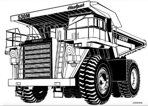
Komatsu Dump Truck 530M Factory Service & Shop Manual

Pages from CEBD008300 – Dump Truck 530M Shop Manual

MKMTS530MOPEK.PDF
Price: $29.99 USD

Complete workshop & service manual with electrical wiring diagrams for Komatsu Dump Truck 530M. It’s the same service manual used by dealers that guaranteed to be fully functional and intact without any missing page.

This Komatsu Dump Truck 530M service & repair manual (including maintenance, overhaul, disassembling & assembling, adjustment, tune-up, operation, inspecting, diagnostic & troubleshooting…) is divided into different sections. Each section covers a specific component or system with detailed illustrations. A table of contents is placed at the beginning of each section. Pages are easily found by category, and each page is expandable for great detail. The printer-ready PDF documents work like a charm on all kinds of devices.

CEBD008300 – Dump Truck 530M Shop Manual.pdf
DG716 – Dump Truck 530M Operation & Maintenance Manual.pdf

EXCERPT:
TABLE OF CONTENTS
SUBJECT . . . SECTION
GENERAL INFORMATION . . . A
STRUCTURES . . . . . B
ENGINE, FUEL, COOLING AND AIR CLEANER . . . . . . C
ELECTRIC SYSTEM (24 VDC. NON-PROPULSION) . . . . D
TRANSMISSION AND TORQUE CONVERTER . . . . . . . F
DRIVE AXLE, SPINDLES AND WHEELS . . . . . G
SUSPENSIONS . . . H
BRAKE CIRCUIT . . . . J
AIR SYSTEM (NO AIR SYSTEM ON THIS TRUCK) . . . . . . K
HYDRAULIC SYSTEM . . . . . . L
OPTIONS AND SPECIAL TOOLS . . . . M
OPERATOR’S CAB . . . . . . N
LUBRICATION AND SERVICE . . . . . . P
ALPHABETICAL INDEX . . . . Q
SYSTEM SCHEMATICS . . . . . R

Assembly
1. Refer to ‘‘Seal Replacement’’ for flange plate seal installation instructions.
2. Place rear pump body (11, Figure 3-6) so that the matching mark made in disassembly step 2 will be facing you. If a new body must be used, make sure the side facing you is the same as the one marked on the old body.
NOTE: Observe that the body has a wide and a narrow boss. The side having the wide boss is always the suction side of the body.
3. Using clean hydraulic oil, coat the inside of pump body (11).
4. Out of the group of parts from the rear section, examine the two isolation plates. You will find that they are slightly different. Choose the one having the rounded edge as shown by the arrow in Figure 3-11. With the rounded edge down, install the plate (on the suction side) in the bottom of the body.
5. Install back-up ring (7, Figure 3-12), O-ring (6), and ring retainer (2).
6. With the bronze side facing up and the rounded trap slots toward the outlet side of the body, slide pressure plate (2, Figure 3-13) down into the gear bores until it rests firmly at the bottom of the pump body. Do not force the plate down the gear bores.
If the plate hangs or binds on the way down, work it back and forth carefully until it slides freely into position.

Posted on

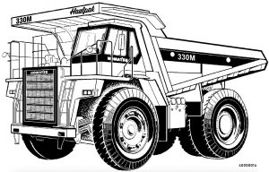
Komatsu Dump Truck 330M Factory Service & Shop Manual

Pages from DG744 – Dump Truck 330M Shop Manual

MKMTS330MOPEK.PDF
Price: $29.99 USD

Complete workshop & service manual with electrical wiring diagrams for Komatsu Dump Truck 330M. It’s the same service manual used by dealers that guaranteed to be fully functional and intact without any missing page.

This Komatsu Dump Truck 330M service & repair manual (including maintenance, overhaul, disassembling & assembling, adjustment, tune-up, operation, inspecting, diagnostic & troubleshooting…) is divided into different sections. Each section covers a specific component or system with detailed illustrations. A table of contents is placed at the beginning of each section. Pages are easily found by category, and each page is expandable for great detail. The printer-ready PDF documents work like a charm on all kinds of devices.

DG642 – Dump Truck 330M Shop Manual.pdf
DG666 – Dump Truck 330M Shop Manual.pdf
DG699 – Dump Truck 330M Shop Manual.pdf
DG713 – Dump Truck 330M Operation & Maintenance Manual.pdf
DG728 – Dump Truck 330M Shop Manual.pdf
DG729 – Dump Truck 330M Operation & Maintenance Manual.pdf
DG744 – Dump Truck 330M Shop Manual.pdf
DG745 – Dump Truck 330M Operation & Maintenance Manual.pdf

EXCERPT:
TABLE OF CONTENTS
SUBJECT . . . . SECTION
GENERAL INFORMATION . . . . A
STRUCTURES . . . . B
ENGINE, FUEL, COOLING AND AIR CLEANER . . . . . C
ELECTRIC SYSTEM (24 VDC. NON-PROPULSION) . . . . D
TRANSMISSION AND TORQUE CONVERTER . . . . . F
DRIVE AXLE, SPINDLES AND WHEELS . . . . . G
SUSPENSIONS . . . . H
BRAKE CIRCUIT . . . . . J
AIR SYSTEM . . . . . K
HYDRAULIC SYSTEM . . . . L
OPTIONS AND SPECIAL TOOLS . . . . . M
OPERATOR’S CAB . . . . N
LUBRICATION AND SERVICE . . . . P
ALPHABETICAL INDEX . . . . Q
SYSTEM SCHEMATICS . . . . . R

STEERING CIRCUIT OPERATION
The steering system is a self-metering , power steering type. When the steering wheel (5, Figure 4-1) is rotated, the steering control valve (6) is actuated causing the oil to flow into the steering cylinder (2).
Extending one steering cylinder while retracting the opposite steering cylinder will change the angle of the front wheels, allowing the operator to steer the truck as desired. the tie rod (3), attach ed to the knuckle (7 ) maintains a constant angular relationship
between the left and rig h t wheels. the truck is also equipped with an automatic emergency steering system to provide oil pressure to the steering circuit in the event of a loss of oil supply from the engine driven steering pump.

Posted on

Komatsu Dump Truck 325M Factory Service & Shop Manual

Pages from DG611 – Dump Truck 325M Shop Manual

MKMTS325MOPEK.PDF
Price: $29.99 USD

Complete workshop & service manual with electrical wiring diagrams for Komatsu Dump Truck 325M. It’s the same service manual used by dealers that guaranteed to be fully functional and intact without any missing page.

This Komatsu Dump Truck 325M service & repair manual (including maintenance, overhaul, disassembling & assembling, adjustment, tune-up, operation, inspecting, diagnostic & troubleshooting…) is divided into different sections. Each section covers a specific component or system with detailed illustrations. A table of contents is placed at the beginning of each section. Pages are easily found by category, and each page is expandable for great detail. The printer-ready PDF documents work like a charm on all kinds of devices.

DG611 – Dump Truck 325M Shop Manual.pdf

EXCERPT:
TABLE OF CONTENTS
SUBJECT . . . . . . SECTION
GENERAL INFORMATION ……… A
STRUCTURES . . . . . . B
ENGINE, FUEL, COOUNG AND AIR CLEANER . . . . . . C
ELECTRIC SYSTEM (24 VDC. NON-PROPULSION) . . . . . . D
TRANSMISSION AND PTO . . . . . . F
DRIVE AXLE, SPINDLES AND WHEELS . . . . . . G
HYDRAIR® II SUSPENSIONS . . . . . . H
BRAKE CIRCUIT . . . . . . • • . J
AIR SYSTEM . . . . . . K
HYDRAULIC SYSTEM . . . . . . L
OPTIONS AND SPECIAL TOOLS . . . . . . M
OPERATOR’S CAB . . . . . . N
LUBRICATION AND SERVICE . . . . . . P
ALPHABETICAL INDEX . . . . . . Q
SYSTEM SCHEMATICS ……….. R

Disassembly
1. Remove capscrews and washers (9, Figure 3-3) and brake drum (8). The brake drum does not need to be removed unless repair or replacement is necessary.
2. Remove oil seal (20), spacer (4), bearing cone (21) and bearing cup (5).
3. Turn wheel hub over and remove bearing cup (12).
4. Remove seal runner (3) from spindle.
Cleaning and Inspection
1. Clean all metal parts in fresh cleaning solvent.
2. Replace any worn or damaged parts.
3. Replace 0-rings and seal runner if worn or damaged.
4. Inspect wheel hub and spindle for damage.
Spindle should be checked in area of inner radius for distress after seal runner has been removed.
Non destructive testing means can be used to check for possible cracks.
Assembly
1. Press bearing cup (12) into bore of wheel hub.
NOTE: Press bearings in using a hydraulic press with sufficient force to fully seat the bearing. Use a feeler gauge to check for gaps between bearing and shoulder. Bearings which are improperly seated can cause major repair problems.
2. Turn wheel hub over and press bearing cup (5) into bore of wheel hub.
3. Place bearing cone (21) into bearing cup (5).
4. Install spacer (4) and press oil seal (20) into wheel hub bore, using care not to damage the seal during assembly.
5. Install brake drum (8) on wheel hub if brake drum was removed.
6. Press seal runner (3) onto spindle.