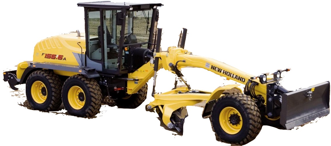
New Holland F106.6, F106.6A, F156.6, F156.6A
Complete workshop & service manual with electrical wiring diagrams for New Holland F106.6, F106.6A, F156.6, F156.6A Grader. It’s the same service manual used by dealers that guaranteed to be fully functional and intact without any missing page.
This New Holland F106.6, F106.6A Grader service & repair manual (including maintenance, overhaul, disassembling & assembling, adjustment, tune-up, operation, inspecting, diagnostic & troubleshooting…) is divided into different sections. Each section covers a specific component or system with detailed illustrations. A table of contents is placed at the beginning of each section. Pages are easily found by category, and each page is expandable for great detail. The printer-ready PDF documents work like a charm on all kinds of devices.
“604.13.567.pdf”
New Holland F106.6, F106.6A Grader Service Manual
Print No. 604.13.567 English III – 2005
579 pages
…
— — — — — — — — — — — — — — — — — — — — —
“87726937A”
New Holland F106.6, F106.6A, F156.6, F156.6A Grader Service Manual
Print No. 87726937A English Edition 12/2007
664 pages
EXCERPT:
F106.6 / F106.6A ATTACHMENT
6.1 CENTRAL ATTACHMENT
6.1.1 REMOVAL – INSTALLATION
Removal
DANGER
Lift and handle all heavy parts with a lifting device of appropriate capacity.
Make sure that groups or parts are held by appropriate slings and hooks.
Make sure that no bystanders are in the vicinity of loads to be lifted.
Proceed as follows:
– move the central attachment sideways, then rest it on the ground by actuating the appropriate cylinders;
– disconnect hydraulic pipes (1) of the front frame from the centre joint, from the swing motor and the brake valves, extract them from guide (2) on the tow bar and place them in a position so that they do not interfere with subsequent operations;
– remove the securing screws and disconnect eyes (3) of the lifting cylinder and the swivelling cylinder from the ball heads on the central attachment, recovering the adjusting shims;
– remove the four securing screws and separate securing plate (4) from the central attachment ball joint;
– support adequately with a cable and hoist, the central attachment complete with blade and ripper (opt.) then remove it using the hoist as required;
– disconnect hydraulic pipes (5) of the swivelling cylinder, support it adequately with a cable and hoist, then remove the four securing screws (6) and remove the cylinder;
– disconnect lifting cylinder hydraulic pipes (7);
– support adequately the lifting cylinder with a cable and hoist, then remove the four securing screws (8) and remove the cylinder;
– repeat the operation for the other lifting cylinder;
…