Posted on

New Holland Kobelco E115SR, E135SR, E135BSR Crawler Excavator Factory Service & Shop Manual

New Holland E115SR, E135SR


INSTANT DOWNLOAD


Complete workshop & service manual with electrical wiring diagrams for New Holland Kobelco E115SR, E135SR, E135BSR Crawler Excavator. It’s the same service manual used by dealers that guaranteed to be fully functional and intact without any missing page.

This New Holland Kobelco E115SR, E135SR, E135BSR Crawler Excavator service & repair manual (including maintenance, overhaul, disassembling & assembling, adjustment, tune-up, operation, inspecting, diagnostic & troubleshooting…) is divided into different sections. Each section covers a specific component or system with detailed illustrations. A table of contents is placed at the beginning of each section. Pages are easily found by category, and each page is expandable for great detail. The printer-ready PDF documents work like a charm on all kinds of devices.

“604.13.426.pdf”
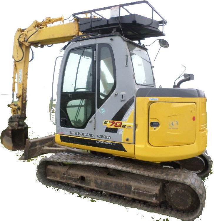
New Holland Kobelco E115SR, E135SR Crawler Excavator Worksop Manual
996 pages
Print No. 604.13.426
Edition: 03/2005 English

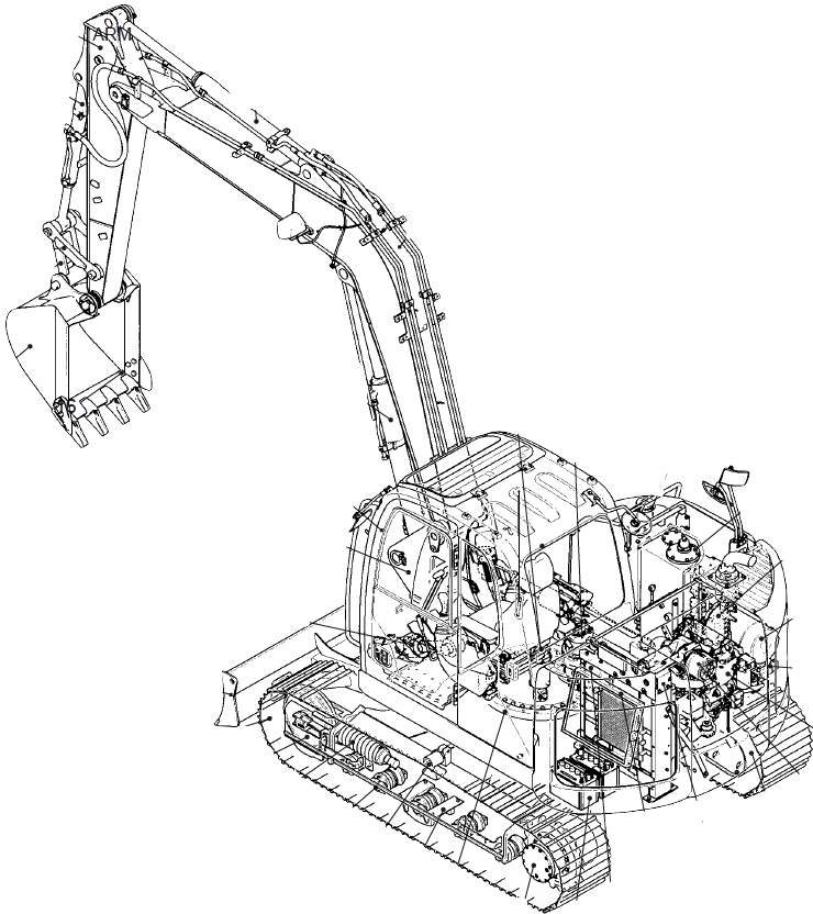
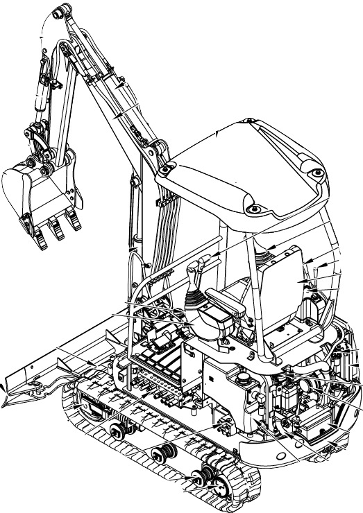
“87743920A – New Holland_Kobelco E135BSR Repair Manual.pdf”

INDEX
SPECIFICATIONS
Section 1 – Outline
Section 2 – Specification
Section 3 – Attachment dimension
MAINTENANCE
Section 11 – Tools
Section 12 – Standard maintenance time schedule Section 13 – Maintenance standard and test procedure
SYSTEM
Section 21 – Mechatro control system Section 22 – Hydraulic system Section 23 – Electric system
Section 24 – Components system Section 25 – Air-conditioner system
DISASSEMBLING
Section 31 – Disassembling and assembling Section 32 – Attachment
Section 33 – Upper structure
Section 34 – Travel system
TROUBLESHOOTING
Section 41 – Troubleshooting (mechatro control) Section 42 – Troubleshooting (Hydraulic) Section 43 – Troubleshooting (Electric)
Section 44 – Troubleshooting (Engine)
ENGINE
Section 51 – Engine
OPT
Section 63 – Mounting the breaker and nibbler & breaker

— — — — — — — — — — — — — — — — — — — — —

EXCERPT:

4.2 REMOVAL AND INSTALLATION OF THE UNIT
(1) Removing the blower unit
1) Remove the connectors connected to the inner/outer air select motor actuator, the blower motor and the blower controller. Also remove the harness from the blower casing.
2) Draw out the inner air filter from the intake casing. Remove four cross-recessed screws T5×14 (T1) from the top of the intake casing, using a screwdriver. Then remove the intake casing.
3) Remove three cross-recessed screws T5×14 (T1) fastening the blower casing with the unit casing. Then separate the blower unit from the air-conditioner unit.
(2) Replacing the blower motor
1) Disconnect the cooling hose that is connected between the blower motor and the blower casing.
2) Remove three cross-recessed screws N5×16 (W) fixed from the bottom of the blower unit casing. Then draw out the blower motor.
Do not separate the fan from the blower motor.
3) Assembly is the reverse order of disassembly.
(3) Replacing the blower controller
1) Remove two cross-recessed screws T4×14 (T1) fixed from the bottom of the blower unit casing and draw out the blower controller.
2) Install a new blower controller in the reverse order of removal.
Do not disassemble the blower controller in any circumstances.


INSTANT DOWNLOAD


Posted on

New Holland E80BMSR/E80MSR Hydraulic Excavator Factory Service & Shop Manual


Pages from 87483766A – E80BMSR Service Manual


INSTANT DOWNLOAD


Complete workshop & service manual with electrical wiring diagrams for New Holland E80BMSR/E80MSR Hydraulic Excavator. It’s the same service manual used by dealers that guaranteed to be fully functional and intact without any missing page.

This New Holland E80BMSR/E80MSR Hydraulic Excavator service & repair manual (including maintenance, overhaul, disassembling & assembling, adjustment, tune-up, operation, inspecting, diagnostic & troubleshooting…) is divided into different sections. Each section covers a specific component or system with detailed illustrations. A table of contents is placed at the beginning of each section. Pages are easily found by category, and each page is expandable for great detail. The printer-ready PDF documents work like a charm on all kinds of devices.

604.13.421 – E80MSR Workshop Manual.pdf
87483766A – E80BMSR Service Manual.pdf

EXCERPT:
32.1.5.4 INSTALLATION OF SWING BRACKET AND CYLINDER
Installation is performed in the reverse order of removal, including the following workings.
(1) Check the dust seal for damages, and replace the faulty dust seal to new one.
(2) Referring to the Chapter 3 “ATTACHMENT DIMENSIONS” replace the worn-out pin and bush to new ones.
(3) Before inserting the pin, apply grease to the shaft area.
(4) Referring to Fig. 32-26, apply Loctite #242 and tighten the capscrew and nuts to prevent the pin from coming out.
(5) Refer to Fig. 32-26 for the shim adjustment at pin installing portion.
(6) For the adjustment for clearance, insert resin shim first, then adjust the clearance with iron shims.


INSTANT DOWNLOAD


Posted on

New Holland Kobelco E70BSR Crawler Excavator Factory Service & Shop Manual

SAMSUNG CAMERA PICTURES

New Holland E70BSR
MNHE70BSROPES.zip
Price: $29.99 USD

Complete workshop & service manual with electrical wiring diagrams for New Holland Kobelco E70BSR Crawler Excavator. It’s the same service manual used by dealers that guaranteed to be fully functional and intact without any missing page.

This New Holland E70BSR service & repair manual (including maintenance, overhaul, disassembling & assembling, adjustment, tune-up, operation, inspecting, diagnostic & troubleshooting…) is divided into different sections. Each section covers a specific component or system with detailed illustrations. A table of contents is placed at the beginning of each section. Pages are easily found by category, and each page is expandable for great detail. The printer-ready PDF documents work like a charm on all kinds of devices.

“87474048A.pdf”
New Holland Kobelco E70BSR Crawler Excavator Worksop Manual
891 pages
Print No. 87474048A
Issued 04/2008 English

“604.13.416 – E70SR Workshop Manual.pdf”

EXCERPT:
13. MAINTENANCE STANDARD AND TEST PROCEDURE
13.6.4 DRAIN RATE OF SWING MOTOR
(1) Purpose
Measure the drain rate of the swing motor and confirm the performances of the swing motor.
(2) Conditions
Hydraulic oil temperature : 45~55°C (113~ 131°F)
Engine revolution : Hi idle
(3) Preparation
1) Stop the engine.
2) Vent air from inside the hydraulic oil tank.
3) Disconnect the swing motor drain hose from its end returning to the hydraulic oil tank and take oil in a container.
4) Put a plug to the tank side.
(4) Measurement ; at Swing Lock
1) Start the engine and put the side faces against the inside of the right or left shoe plate.
2) Relieve the swing motor at full stroke of the swing motion.
3) Receive in a container the amount of drain accumulated in 30 seconds of relieving.

Posted on

New Holland E9SR/E16/E18/E20.2SR/E22.2SR/E27.2SR Excavators Factory Service & Shop Manual


Pages from 87743534 – E16B-E18B Workshop Manual

MNHE9E27OPES.zip
Price: $29.99 USD

Complete workshop & service manual with electrical wiring diagrams for New Holland E9SR/E16/E18/E20.2SR/E22.2SR/E27.2SR Excavators. It’s the same service manual used by dealers that guaranteed to be fully functional and intact without any missing page.

This New Holland E9SR/E16/E18/E20.2SR/E22.2SR/E27.2SR Excavators service & repair manual (including maintenance, overhaul, disassembling & assembling, adjustment, tune-up, operation, inspecting, diagnostic & troubleshooting…) is divided into different sections. Each section covers a specific component or system with detailed illustrations. A table of contents is placed at the beginning of each section. Pages are easily found by category, and each page is expandable for great detail. The printer-ready PDF documents work like a charm on all kinds of devices.

FILELIST:
604.13.391.00 – E9SR Excavator Workshop Manual.pdf
604.13.396 – E16-E18 Workshop Manual.pdf
604.13.401 – Hydraulic Excavator E20.2SR – E22.2SR – E27.2SR Workshop Manual.pdf
87677528A – E18SR Workshop Manual.pdf
87743534 – E16B-E18B Workshop Manual.pdf

EXCERPT:
TABLE OF CONTENTS
1 – DESCRIPTION
2 – TECHNICAL SPECIFICATIONS
3 – WORKING ATTACHMENT
11 – TOOLS
12 – TABLE OF STANDARD MAINTENANCE TIMES
13 – MAINTENANCE STANDARDS AND INSPECTION
PROCEDURES
22 – HYDRAULIC SYSTEM
23 – ELECTRICAL SYSTEM
24 – MAIN COMPONENTS
32 – WORKING ATTACHMENT REMOVAL AND
INSTALLATION
33 – UPPER FRAME
34 – TRAVEL
42 – TROUBLESHOOTING – HYDRAULIC SYSTEM
43 – TROUBLESHOOTING – ELECTRICAL SYSTEM
44 – TROUBLESHOOTING – ENGINE
51 – ENGINE

24. MAIN COMPONENTS
The control valve is divided into four parts:
Manual operation: swing.
Pilot operation: right and left travel, boom, arm, bucket, slewing, independent travel and conflux, dozer, additional equipment (nibbler and hydraulic hammer).
Accessories: ports P1 and P2, port P3 (in common with independent travel and conflux).
Auxiliary accessories (valve): main relief valve P1, P2, overpressure valve, anticavitation valve.
Operating section examples.

Posted on

New Holland D350 Crawler Dozer Factory Service & Shop Manual


New_Holland_D350

MNHD350OPES.zip
Price: $29.99 USD

Complete workshop & service manual with electrical wiring diagrams for New Holland D350 Crawler Dozer. It’s the same service manual used by dealers that guaranteed to be fully functional and intact without any missing page.

This New Holland D350 Crawler Dozer service & repair manual (including maintenance, overhaul, disassembling & assembling, adjustment, tune-up, operation, inspecting, diagnostic & troubleshooting…) is divided into different sections. Each section covers a specific component or system with detailed illustrations. A table of contents is placed at the beginning of each section. Pages are easily found by category, and each page is expandable for great detail. The printer-ready PDF documents work like a charm on all kinds of devices.

84568077A – D350 Service Manual.pdf – 354 pages

SUMMARY
GENERALITIES SECT. 0
ENGINE SECT. 1
TRANSMISSION SECT. 2
FINAL DRIVES SECT. 3
BRAKES AND STEERING DIFFERENTIAL SECT. 4
UNDERCARRIAGE SECT. 5
DOZING EQUIPMENT
HYDRAULIC SYSTEM SECT. 6
ELECTRICAL SYSTEM SECT. 7

EXCERPT:
TRANSMISSION
2.4.6 REINSTALLATION OF TRANSMISSION When reinstalling the transmission group on the machine please consider the following:
– clean accurately the two mating surfaces between the transmission housing and the rear transmission housing and apply adhesive compound before mating the two parts;
– make sure that reverse clutch engagement oil delivery manifold (5, fig. 2-80) is complete with O-Rings at the tips;
– remove the transmission from the overhaul stand using adjustable chain (2) and lifting hook (1) (fig. 2-50);
– use the lifting eyes and auxiliary hook 380000963 already used for the removal, paying attention that during this phase the O-Ring fitted at the tip of the bearing retaining cover is not damaged;
– lubricate adequately the matching splines with the bevel pinion with grease MOLYKOTE BR2 PLUS or MOLYGUARD LMP7180.