Posted on

Case CX350C Crawler Excavator Workshop Repair & Service Manual


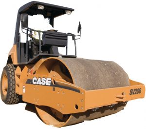
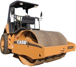
Case SV208, SV210, SV212, SV216, SV223, SV228

MCSCX350COPES.zip
Price: $29.99 USD

Complete digital official shop manual contains service, maintenance, and troubleshooting information for the Case CX350C Crawler Excavator. Diagnostic and repair procedures are covered in great detail to repair, maintain, rebuild, refurbish or restore your Case CX350C like a professional mechanic in local service/repair workshop. This cost-effective quality manual is 100% complete and intact as should be without any missing pages. It is the same factory shop manual used by dealers that guaranteed to be fully functional to save your precious time.

This manual for Case CX350C Crawler Excavator is divided into different sections. Each section covers a specific component or system and, in addition to the standard service procedures, includes disassembling, inspecting, and assembling instructions. A table of contents is placed at the beginning of each section. Pages are easily found by category, and each page is expandable for great detail. It is in the cross-platform PDF document format so that it works like a charm on all kinds of devices. You do not need to be skilled with a computer to use the manual.

“84402832.pdf”
Case CX350C Tier 4 Crawler Excavator Service Manual
1,950 pages
1st edition English
August 2011

“84406998.pdf”
Case CX350C Tier 4 Crawler Excavator Operator’s Manual
254 pages
1st edition English
January 2011

EXCERPT:
Removal and Installation of Counterweight
CAUTION
• Be sure to stop the engine before beginning work.
• Be sure to inspect the wire rope and other lifting equipment before beginning work.
• Do not stand or pass under the suspended load.
• Thoroughly secure the removed counterweight with the wire ropes and liftcrane so that it does not fall over.
Items to prepare
• Box wrench (50 mm)
• Balance lifting device
• Shackles (with the required lifting capacity) x 4
• Wire rope (with the required breaking load) x 4
• Liftcrane (with the required lifting capacity)
• Wood planks, etc.
• Rag
• Cleaning fluid
Removal of Counterweight
1. Remove the following before beginning work.。
• Engine hood, gas damper and lock stay
• Rear view camera and electrical parts bracket
2. Install the shackles (1), and then use the wire ropes (2) and liftcrane to secure the counterweight so that it does not fall during removal and installation operations.
3. Use a box wrench (50 mm) to remove the 4 bolts (1) at the bottom section of the counterweight.
4. Use the wire ropes and liftcrane to lift and remove the counterweight.
• Move the counterweight about 50 cm to the rear while lifting it so that it does not interfere with the housing, engine parts and pipes.
5. Thoroughly check that the location is safe before lowering the counterweight on wood planks (1).
• Thoroughly secure the counterweight with the wire ropes and liftcrane so that it does not fall over.
Installation of Counterweight
1. Install the shackles (1), and then use the wire ropes (2) and liftcrane to secure the counterweight so that it does not fall during removal and installation operations.
2. Use the wire ropes and liftcrane to lift and install the counterweight.
• Suspend the counterweight so that it does not interfere with the housing, engine parts and pipes.
3. Coat the threaded section of the bolt (1) with Loctite, and use a box wrench (50 mm) to fasten the counterweight using the 4 bolts (1) and 4 high-strength washers (2) at the bottom section of the counterweight.
Tightening torque: 1862 – 2058 N·m
4. Install the following after finishing work.
• Engine hood, gas damper and lock stay
• Rear view camera and electrical parts bracket

Removal and Installation of Boom
CAUTION
• Stop the machine on a level location with good footing.
• Be sure to stop the engine before beginning work.
• When working together with others, always be sure to exchange signals and pay adequate attention to safety.
• Always wear protective devices (protective eyewear and safety shoes, etc.) when working with a hammer.
• Be sure to inspect the nylon sling and other lifting equipment before beginning work.
• Do not stand or pass under the suspended load.
Items to prepare
• Wrenches (10 mm、19 mm、22 mm、30 mm、36 mm、41 mm)
• Hexagon wrench (12 mm)
• Slide hammer (24 mm)
• Nylon sling (with the required lifting capacity)
• Liftcrane (with the required lifting capacity)
• Marking pen
• Cap
• Plug
• Rag
• Striking rod
• Cleaning fluid
• Wood piece
• Square wooden pieces
• Wire
Removal of Boom
• Remove the bucket. (For details, see “Removal and Installation of Bucket”.)
• Remove the bucket link. (For details, see “Removal and Installation of Bucket Link”.)
• Remove the bucket cylinder. (For details, see “Removal and Installation of Bucket Cylinder”.)
• Remove the arm cylinder. (For details, see “Removal and Installation of Arm Cylinder”.)
• Remove the arm. (For details, see “Removal and Installation of Arm”.)
• This section explains the procedure for when attaching the boom cylinder to the frame.
When removing the boom cylinder too, see “Removal and Installation of Boom Cylinder”.
1. Bring the boom (1) top in contact with the ground.
2. Use a wrench (19 mm) to remove the grease hoses on the left and right sides (1).
• Use caps or plugs to prevent any entry of water, dust or dirt.
3. Use a wrench (36 mm) to remove the double nuts
(1) and bolt (2), and then remove the fastening ring (3).
Also, remove the cab side in the same way.
4. Use a hammer (2) and striking rod (3) to push the pin (1) out.
Use a liftcrane and nylon slings (4) to hold the boom cylinders (right) (left) so that they does not fall.
5. Start the engine, lower the boom at idle, and retract the boom cylinder (1) (2) rod.
6. Tie the cylinder rods on the left and right sides with wire (1) so that they cannot come out.
7. Secure the base of the boom cylinder with the wood piece (1).
8. Lower the boom cylinders (right) (left) and let them rest on the wood piece (1).
• Remove the cab side boom cylinder from the boom in the same way.
9. Install the pin (1) removed in Step 4.
Use a wrench (36 mm) to tighten the bolt (3) with the 2 double nuts (2), and then install the fastening ring (4).
Also, install the cab side in the same way.
10. Use wrenches (41 mm) to remove the hoses (1), (2), (3).
Use a hexagon wrench (12 mm) to remove the
4 hexagon socket head bolts (5) and the 2 split flanges (6), and then remove the hose (4).
• Mark the hoses and lines so that the connectors match at the time of assembly.

Posted on

Case SV208, SV210, SV212, SV216, SV223, SV228 Factory Service & Shop Manual


Case SV208, SV210, SV212, SV216, SV223, SV228

INSTANT DOWNLOAD

Complete workshop & service manual with electrical wiring diagrams for Case SV208, SV210, SV212, SV216, SV223, SV228. It’s the same service manual used by dealers that guaranteed to be fully functional and intact without any missing page.

This Case SV208, SV210, SV212, SV216, SV223, SV228 service & repair manual (including maintenance, overhaul, disassembling & assembling, adjustment, tune-up, operation, inspecting, diagnostic & troubleshooting…) is divided into different sections. Each section covers a specific component or system with detailed illustrations. A table of contents is placed at the beginning of each section. Pages are easily found by category, and each page is expandable for great detail. The printer-ready PDF documents work like a charm on all kinds of devices.

“Cre 7-29532.pdf”
Case Vibratory Rollers SV Series (SV208, SV210, SV212, SV216, SV223, SV228) Service Manual
323 pages

“47688018.pdf”
Case SV208, SV210, SV212, SV216 Tier 3 Vibratory Rollers Service Manual
442 pages
Part number 47688018; 2nd edition English; June 2014; Replaces part number 87480985NA

EXCERPT:
SECTION 41 – STEERING – CHAPTER 1
DISASSEMBLY AND ASSEMBLY OF STEERING WHEEL
Remove the steering wheel cup (6) and the nut (21) and insert tool No. 1 under the steering wheel. Remove the steering wheel using a steering wheel spanner, dismantle the steering wheel bracket (1) and slide it with the steering rod (2) out from the steering column.
Remove the snap rings (30), (31) and press shaft (2) out together with the bearing. Remove the bearing (9) from the shaft.
Press the bearing on the shaft (the bearing must be degreased and fresh grease must be applied), secure it with the snap ring (31), press it into bracket (1), secure with the snap ring (30) and mount it to the steering column.
Check that no clearance can be detected between bracket (1) and the steering column after the shaft has been set in steering. Mount the steering wheel.

INSTANT DOWNLOAD

Posted on

Case CX800B Crawler Excavator Workshop Repair & Service Manual


Case CX800B

MCSCX800BOPES.zip
Price: $29.99 USD

Complete digital official shop manual contains service, maintenance, and troubleshooting information for the Case CX800B Tier 3 Crawler Excavator. Diagnostic and repair procedures are covered in great detail to repair, maintain, rebuild, refurbish or restore your vehicle like a professional mechanic in local service/repair workshop. This cost-effective quality manual is 100% complete and intact as should be without any missing pages. It is the same factory shop manual used by dealers that guaranteed to be fully functional to save your precious time.

This manual for Case CX800B Crawler Excavator is divided into different sections. Each section covers a specific component or system and, in addition to the standard service procedures, includes disassembling, inspecting, and assembling instructions. A table of contents is placed at the beginning of each section. Pages are easily found by category, and each page is expandable for great detail. It is in the cross-platform PDF document format so that it works like a charm on all kinds of devices. You do not need to be skilled with a computer to use the manual.

FILELIST:
84176583C – Crawler Excavator CX800B Tier 3 Service Manual.pdf
84374208 – Crawler Excavator CX800B Tier 3 Service Manual – 1 – GENERAL INFORMATION_2 – ENGINE_3 – FUEL SYSTEM.pdf
84374209 – Crawler Excavator CX800B Tier 3 Service Manual – 4 – ELECTRICAL SYSTEM (Section 4000 – 4020).pdf
84374210 – Crawler Excavator CX800B Tier 3 Service Manual – 4 – ELECTRICAL SYSTEM (Section 4021 – 4023).pdf
84374211 – Crawler Excavator CX800B Tier 3 Service Manual – 5 – UNDERCARRIAGE_6 – DRIVE TRAIN.pdf
84374212 – Crawler Excavator CX800B Tier 3 Service Manual – 8 – UPPERSTRUCTURE HYDRAULICS.pdf
84374213 – Crawler Excavator CX800B Tier 3 Service Manual – 9 – UPPERSTRUCTURE.pdf
84374214 (Replaces 84176583ANA) – Crawler Excavator CX800B Tier 3 Service Manual – Complete Contents.pdf

EXCERPT:
2 Disassembly
1 Precautions
Begin motor disassembly only after thoroughly reading the precautions below.
[1] When performing disassembly, always wear protective devices such as a helmet, goggles and safety shoes.
[2] Use the specified tools when performing disassembly.
[3] Remove all lines connected to the motor and remove the motor from the mother machine only after making sure that the machine is on a level surface and there are no external forces acting on rotating parts so that the mother machine does not operate uncontrollably when the motor is removed.
[4] To prevent foreign matter from entering the lines and motor when removing the motor from the mother machine, sufficiently clean off mud and dirt adhered around the motor before removing lines connected to the motor.
[5] When removing lines connected to the motor, hydraulic oil from inside the lines will spray out. For this reason, remove these lines only after removing pressure from inside the lines and preparing an oil pan. To prevent injuries
due to the motor falling when transporting it by lifting the motor with a liftcrane, lift the machine with the eyebolts mounted in the positions indicated in the diagram below.
[6] The motor is filled with hydraulic oil. Before disassembling the motor, prepare an oil pan and drain the hydraulic oil from the motor.
[7] To prevent injuries during disassembly, prepare a waist-high, stable work platform to perform work on.
[8] The motor comprises high-precision parts. For this reason, foreign matter adhering to parts can be damaging.
Motor disassembly should be done in an inside space without dust, and mud and dirt should be prevented from adhering to parts.
[9] The motor comprises high-precision parts. For this reason, dents and scratching on part surfaces can be damaging.
Be very careful when handling parts during disassembly and do not create any dents or scratching.
[10]To prevent personal injury and damage to parts during disassembly, do not force disassembly of parts which are especially tight to disassemble.
2 Tightening torque
The tightening torque for each fastening section are indicated in the text.
3 Travel motor disassembly procedure
Perform disassembly by observing the precautions listed in 2. (1) and following the procedure indicated below
[1] Removal of cap assemblies (2-6).
Secure the motor on top of the stable work platform, loosen the 8 hexagon socket head bolts (2-6-6) and remove the cap assemblies (2-6). Next, remove the spring seats (2-5), springs (2-4), and spring seats (2-3).
NOTICE:
The cap assemblies (2-6) are pressed out by the springs (2-4). On the other hand, if the cap assemblies
(2-6) do not come off even when the bolt is loosened, hit the cap with a plastic hammer. For this reason, observe the following precautions when working.
• Loosen the hexagon socket head bolts (2-6-6)
evenly.
• Loosen the hexagon socket head bolts (2-6-6) while pressing down the cap assemblies (2-6).
• When hitting the cap assemblies (2-6), do so with the bolts (2-6-6) only partially loosened.
If the bolts (2-6-6) are removed, there is a danger of the cap assemblies (2-6) flying out and injuring someone.

Posted on

Case 845B/845B DHP/865B/865B VHP/865B AWD/885B/885B DHP/885B AWD Workshop Repair & Service Manual


Case 845B, 865B, 885B

MCS845885BOPES.zip
Price: $29.99 USD

Complete digital official shop manual contains service, maintenance, and troubleshooting information for the Case 845B, 845B DHP, 865B, 865B VHP, 865B AWD, 885B, 885B DHP, 885B AWD Grader. Diagnostic and repair procedures are covered in great detail to repair, maintain, rebuild, refurbish or restore your 845B/845B DHP/865B/865B VHP/865B AWD/885B/885B DHP/885B AWD like a professional mechanic in local service/repair workshop. This cost-effective quality manual is 100% complete and intact as should be without any missing pages. It is the same factory shop manual used by dealers that guaranteed to be fully functional to save your precious time.

This manual for Case 845B, 845B DHP, 865B, 865B VHP, 865B AWD, 885B, 885B DHP, 885B AWD Grader is divided into different sections. Each section covers a specific component or system and, in addition to the standard service procedures, includes disassembling, inspecting, and assembling instructions. A table of contents is placed at the beginning of each section. Pages are easily found by category, and each page is expandable for great detail. It is in the cross-platform PDF document format so that it works like a charm on all kinds of devices. You do not need to be skilled with a computer to use the manual.

FILELIST:
71114392 – 845B, 845B DHP, 865B, 865B VHP, 865B AWD, 885B, 885B DHP, 885B AWD Grader Service Manual.pdf
84300294 – 845B, 865B, 885B Grader Operators’s Manual.pdf

EXCERPT:

6000-48
INPUT SHAFT, OUTPUT SHAFT AND CLUTCHES KV / KR / K1 / K2 / K3 / K4
Removal
Force out both cylindrical pins (1).
Loosen bolted connection (2) between housing front and rear part and separate housing rear part by means of lifting device.
(S) Eye bolt M20 0636 804 003
(S) Eye nut M12 0664 462 774
Loosen bolted connection (1) of oil screen sheets.
Remove output shaft (1) and lower oil screen sheet (2) from housing.
FIGURE 75
FIGURE 76
FIGURE 77
Remove all rectangular rings (1) from the clutches and all Orings (2) from the oil tubes.
Use lifting device to bring housing rear part (1) into contact position with housing front part (2) again.
(S) Eye bolt M20 0636 804 003
(S) Eye nut M12 0664 462 774
Due to the installation conditions, the removal of single clutches without using the special tool is not possible. Risk of injury.
Fix all clutches by means of handle (1).
(S) Handle 5870 260 010
Separate housing rear part incl. clutches from housing front part by means of the lifting device and attach it to the assembly truck.
Loosen cylindrical screws of oil tubes (1) in the housing front part and remove them.
NOTE: The suction tube (2) and the lubrication lines
(3) are rolled in and are highly difficult to remove. In case of damage, use of the appropriate ZF special tool is imperative for fitting or replacing these components.
(S) Suction tube 0501 210 712
(S) Rolling tool 5870 600 003
Remove bearing outer rings (arrows) from the housing front part.
NOTE: If, contrary to the ZF recommendation, the tapered roller bearings of clutches, input and output are not replaced, it is imperative to ensure the previous pairing (bearing outer ring/ bearing inner ring).
Bearing outer ring and bearing inner ring must be marked.
Lift the clutches out of the housing in numerical order as described in the legend.
Remove bearing outer rings (arrows) from the housing rear part.
NOTE: If, contrary to the ZF recommendation, the tapered roller bearings of clutches, input and output are not replaced, it is imperative to ensure the previous pairing (bearing outer ring/ bearing inner ring).
Bearing outer ring and bearing inner ring must be marked.

Posted on

Case 750L, 850L Crawler Dozer Workshop Repair & Service Manual


Case 721D

MCS750850LOPES.zip
Price: $29.99 USD

Complete digital official shop manual contains service, maintenance, and troubleshooting information for the Case 750L, 850L Crawler Dozer. Diagnostic and repair procedures are covered in great detail to repair, maintain, rebuild, refurbish or restore your Case 750L, 850L Crawler Dozer like a professional mechanic in local service/repair workshop. This cost-effective quality manual is 100% complete and intact as should be without any missing pages. It is the same factory shop manual used by dealers that guaranteed to be fully functional to save your precious time.

This manual for Case 750L, 850L Crawler Dozer is divided into different sections. Each section covers a specific component or system and, in addition to the standard service procedures, includes disassembling, inspecting, and assembling instructions. A table of contents is placed at the beginning of each section. Pages are easily found by category, and each page is expandable for great detail. It is in the cross-platform PDF document format so that it works like a charm on all kinds of devices. You do not need to be skilled with a computer to use the manual.

“87728445.pdf”
750L, 850L TIER 3 Crawler Dozer Repair Manual
1,513 pages

“87479855.pdf”
750L, 850L TIER 3 Crawler Dozer Operator’s Manual
144 pages

EXCERPT:
POWER PRODUCTION – STARTING SYSTEM
Engine starter- Remove
1. Park the machine on a level surface.
2. Lower the attachments to the floor.
3. Apply the parking brake and stop the engine, remove the key from the ignition switch.
4. Fasten a Do Not Operate tag to the instrument panel.
5. Open the left rear ROPS door.
6. Put the battery disconnect switch in the off position.
7. Open the right-hand side engine panel.
8. Remove the right-hand side lower panel.
NOTE: If two batteries are installed, there are two battery cables connected to the starter.
9. Fasten identification tags to the wires for the starter.
Disconnect the wire from the bottom of the starter solenoid. Pull the rubber boot away from the terminal
and disconnect the battery cable(s) and the three wiring harness from the side of the starter solenoid.
10. Support the starter. Loosen and remove the two bolts, washers and clamp. Remove the starter.
Next operation:
Engine starter- Disassemble (B.SO.A) or Engine starter- Preliminary test (B.SO.A).
Engine starter- Install
Prior operation:
Engine starter- Electrical test (B.80.A),
1. Position the starter in the flywheel housing.
2. Install the two bolts, washers, and clamp to fasten the starter to the flywheel housing. Torque the bolts to 68 – 77 Nm (50 – 57 lb ft).
3. Connect the battery cable(s) and the three wiring harness wires to the side of the starter solenoid and torque to 2.6 – 4.6 Nm (23 – 41 lb in). Connect the wire to the bottom of the starter solenoid and torque to 17.7- 24.5 Nm (13- 18 lb ft). Push the rubber boot onto the terminal.
4. Install the right-hand side lower panel.
5. Close the right-hand side engine panel.
6. Put the battery disconnect switch in the on position.
7. Close the left rear ROPS door.
8. Remove the Do Not Operate tag from the instrument panel.
Engine starter – Preliminary test
Prior operation:
Engine starter – Remove (B.SO.A).
Prior operation:
Before starting the No-Load Test the following testing equipment must be obtained:
(a) One Sun Electric CAS10147 Tester, an equivalent tester, or separate pieces oftest equipment.
(b) One hand held tachometer to measure the speed of the armature shaft.
(c) One remote starter button to actuate the starter.
(d) One fully charged 12 volt battery to supply the electricity to turn the starter.
Prior operation:
Before starting the No-Load test, check to see if:
(a) The gear on the starter drive can be pulled out of the starter housing.
(b) The starter drive can be turned. To do this, pull the gear on the starter drive out of the starter drive housing. Turn the gear to turn the starter drive and the armature. If the starter can not be turned, disassemble the starter and make repairs as needed.
NOTE: The starter needs to be removed from the engine before the No-Load Test can be done.
NOTE: The No-Load Test should be done at 20 oc ( 68 °F).
1. If the Sun Electric CAS10147 is being used, turn the AMP Range switch to ( 0- 100 amps), turn the Volt
2. Range switch to ( 18 – 40 volts), flip the Volt Lead switch to the “EXT.” position and turn the Load Control dial to the “OFF” position.
3. If the other test equipment is being used, connect the test equipment according to the above procedure and follow the manufacturer’s instructions.
Fasten the starter in a vise or use another method to prevent the starter from moving. This must be done to prevent personal injury.
Connect the positive battery cable to the battery terminal on the starter solenoid and the negative battery cable to the mounting flange of the starter.
(1) Positive battery cable
(2) Battery terminal
(3) Negative battery cable