Posted on

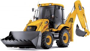
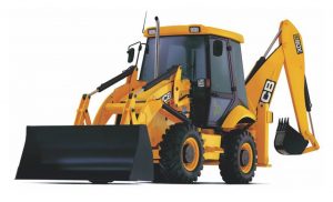
JCB 3CX, 4CX, 214e, 214, 215, 217 & Variants Backhoe Loader Factory Service & Shop Manual


JCB 3CX, 4CX, 214e, 214, 215, 217


INSTANT DOWNLOAD


Complete workshop & service manual with electrical wiring diagrams for JCB 2D, 2DS, 3, 3C, 3CS, 3CX, 3D, 4C, 4CN, 4CX, 5CX, 214e, 214, 214S, 215, 215E, 215S, 217, 217S, 700, 1400B, 1550B, 1700B & Variants Backhoe Loader. It’s the same service manual used by dealers that guaranteed to be fully functional and intact without any missing page.

This JCB 2D, 2DS, 3, 3C, 3CS, 3CX, 3D, 4C, 4CN, 4CX, 5CX, 214e, 214, 214S, 215, 215E, 215S, 217, 217S, 700, 1400B, 1550B, 1700B Backhoe Loaders service & repair manual (including maintenance, overhaul, disassembling & assembling, adjustment, tune-up, operation, inspecting, diagnostic & troubleshooting…) is divided into different sections. Each section covers a specific component or system with detailed illustrations. A table of contents is placed at the beginning of each section. Pages are easily found by category, and each page is expandable for great detail. The printer-ready PDF documents work like a charm on all kinds of devices.

FILELIST:745MB PDF
9802-8000 – JCB 3C, 3CX, 3D, 3DS, 4CT Backhoe Loader Parts Catalog.pdf
9803-1200 – Leyland 38 TD and 4/98NT Engine Service Workshop.pdf
9803-3250 – JCB 3C, 3CX, 3D, 4C, 4CN, 4CX, 214, 215, 217 (S.N. 290000&up) Excavator Loader Service Manual.pdf
9803-3257U – JCB 200 Series (3CX, 1400B, 1550B, 1700B) Backhoe Loader (SN 334,001&up) Service Manual.pdf
9803-3260 Issue 9 – JCB 3CX, 4CX & Variants Backhoe Loader Service Manual.pdf
9803-3270 – JCB 3CX, 4CX, 214, 215, 217 & Variants Backhoe Loader Service Manual.pdf
9803-3280 Issue 4 – JCB 3CX, 4CX, 214e, 214, 215, 217 & Variants Backhoe Loader Service Manual.pdf
9803-3280 Issue 9 – JCB 3CX, 4CX, 214e, 214, 215, 217 & Variants Backhoe Loader Service Manual.pdf
9803-3290 – JCB 3C, 3CX, 4CX Backhoe Loader Service Manual.pdf
9813-0250 – 3C, 3CX, 3CX Super, 4C, 4CX, 5CX, 214, 214S, 215, 215E, 215S, 217, 217S Backhoe Loader Service Manual.pdf
PCA 110M – BMC 3-cyl & 4-cyl Engien Parts Catalog.pdf
9803-3200 – JCB 2D, 2DS, 3, 3C, 3CS, 3D, 700 Excavator Loader Service Manual.pdf
JCB 2, 3, 3C & 4C (MK1) Operator’s Parts Book.pdf
JCB 2D-2DS-3-3C-3CS-3D-700 (MK2 & MK3 Range) (Manual Gearbox & Torque Converter) Excavator Loader Workshop Manual.pdf

EXCERPT:
Excavator Valve
Removal and Replacement Variable Flow
! WARNING
Make the machine safe before working underneath it. Park the machine on level ground, lower the arms. Apply the parking brake, put the transmission in neutral and stop the engine. Chock both sides of all four wheels.
Disconnect the battery, to prevent the engine being started while you are beneath the machine.
! DANGER
Hydraulic Pressure
Hydraulic fluid at system pressure can injure you. Before disconnecting or connecting hydraulic hoses, stop the engine and operate the controls to release pressure trapped in the hoses. Make sure the engine cannot be started while the hoses are open.
Removal
1 Sideshift the carriage to one side as shown (sideshift machines only). Lower the backhoe and loader end to the ground and stop the engine.
2 Operate the valve block levers back and forth to vent residual pressure.
3 Remove the hose guide A (this makes access to the valve block easier).
3 Remove clevis pins B to disconnect the control levers from the valve block spools.
4 Disconnect all hydraulic hoses from the valve block and plug all orifices to prevent ingress of dirt. Label each hose before disconnecting, this will ensure correct position when refitting.
5 Insert two M10 bolts through the eye end spools (three spools each end) as shown. Make sure the bolt has a retaining nut on each end. When the bolts are in place thread suitable slings around the bolts as shown.
! CAUTION
This component is heavy. Do not attempt to remove it unless its weight is held by a sling. Make sure that the sling is attached to a suitable lifting appliance.
7 Remove nuts C and lower the valve block to the ground.

INSTANT DOWNLOAD


Posted on

JCB 2CX, 2DX, 210, 212 & Variants Backhoe Loader Factory Service & Shop Manual


Pages from 9803-7110 – JCB 2CX, 2DX, 210, 212 & Variants Backhoe Loader Service Manual


INSTANT DOWNLOAD


Complete workshop & service manual with electrical wiring diagrams for JCB Backhoe Loader 2CX, 2DX, 210, 210S, 210SL, 212, 212S & Variants. It’s the same service manual used by dealers that guaranteed to be fully functional and intact without any missing page.

This JCB Backhoe Loader 2CX, 2DX, 210, 210S, 210SL, 212, 212S & Variants service & repair manual (including maintenance, overhaul, disassembling & assembling, adjustment, tune-up, operation, inspecting, diagnostic & troubleshooting…) is divided into different sections. Each section covers a specific component or system with detailed illustrations. A table of contents is placed at the beginning of each section. Pages are easily found by category, and each page is expandable for great detail. The printer-ready PDF documents work like a charm on all kinds of devices.

FILELIST:
9802-8860 – JCB 212SU LE Backhoe Loader Part Catalog.pdf
9803-7110 – JCB 2CX, 2DX, 210, 212 & Variants Backhoe Loader Service Manual.pdf
9803-7130 – JCB 210S, 210SL, 212S Backhoe Loader Service Manual.pdf
9813-0600 – JCB 2DX BSIII India Backhoe Loader Service Manual.pdf

EXCERPT:
Section 1 – General Information
Section 2 – Care and Safety
Section 3 – Maintenance
Section B – Body and Framework
Section C – Electrics
Section D – Controls
Section E – Hydraulics
Section F – Transmissions
Section G – Brakes
Section H – Steering
Section K – Engine

Removal and Replacement
Removal
1 Park the machine on firm level ground. Engage the parking brake and set the transmission to neutral.
2 Lower the loader shovel to the ground.
3 Make sure that the backhoe assembly is set central to the mainframe as shown. If necessary `sideshift’ the backhoe into a central position.
4 Remove the stabiliser foot D, refit pivot pin to engage stabiliser ram.
5 K Fig 2. ( T B-68). Remove the inner leg:
a Disconnect hydraulic hoses to stabiliser ram.
b Use suitable lifting equipment, lift the inner leg clear.
c Remove the wear pads.
Replacement
Replacement is a reversal of the removal sequence.
Select suitable size upper pads A to achieve a maximum permissible float of 1 mm (0.039 in).
Make sure that the bottom pads C are held in position before guiding the inner leg into position. If the lower pads are not secured then the inner leg could dislodge the pads during assembly.
When the inner leg is in position adjust the bottom pads.
K Wear Pad – Adjustment ( T B-66).
Apply a high pressure grease such as JCB HP Grease (part number 4003/2000) to the threads of pad B.


INSTANT DOWNLOAD


Posted on

JCB 1CX, 208S Backhoe Loader Factory Service & Shop Manual


Pages from 9803-9960 – JCB 1CX Backhoe Loader (Series 1 & Series 2) Service Manual

MJCB1CXOPEK.zip
Price: $29.99 USD

Complete workshop & service manual with electrical wiring diagrams for JCB 1CX, 208S Backhoe Loader. It’s the same service manual used by dealers that guaranteed to be fully functional and intact without any missing page.

This JCB 1CX, 208S Backhoe Loader service & repair manual (including maintenance, overhaul, disassembling & assembling, adjustment, tune-up, operation, inspecting, diagnostic & troubleshooting…) is divided into different sections. Each section covers a specific component or system with detailed illustrations. A table of contents is placed at the beginning of each section. Pages are easily found by category, and each page is expandable for great detail. The printer-ready PDF documents work like a charm on all kinds of devices.

9803-8550 – JCB 1CX, 208S Backhoe Loader Service Manual.pdf
9803-9960 – JCB 1CX Backhoe Loader (Series 1 & Series 2) Service Manual.pdf

EXCERPT:
General Information 1
Care & Safety 2
Routine Maintenance 3
Attachments A
Body & Framework B
Electrics C
Controls D
Hydraulics E
Transmission F
Brakes G
Engine K

Service Manual – 1CX
Section 1 – General Information
Section 2 – Care and Safety
Section 3 – Maintenance
Section A – Attachments
Section B – Body and Framework
Section C – Electrics
Section E – Hydraulics
Section F – Transmission
Section G – Brakes
Section J – Tracks
Section K – Engine

Pumps
Removal and Replacement
Fig 1.
Note: The illustration shows an early pump but although later pumps are visually different the same procedure applies.
Removal
Disconnect the battery. Remove the front floor plates. See Section 3. Drain the hydraulic tank. Disconnect the microswitch at the base of the seat. Remove the two front and the left hand rear bolts securing the seat. Slacken but do not remove the right hand rear bolt. The seat can now be rotated towards the rear of the machine. Unclip the wiring loom and battery lead from the front seat mounting rail. Remove the seat mounting rail.

Posted on

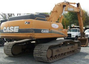
Case CX290B Crawler Excavators Workshop Repair & Service Manual


Case CX290B

MCSCX290BOPES.zip
Price: $29.99 USD

Complete digital official shop manual contains service, maintenance, and troubleshooting information for the Case CX290B Crawler Excavators. Diagnostic and repair procedures are covered in great detail to repair, maintain, rebuild, refurbish or restore your Case CX290B Crawler Excavators like a professional mechanic in local service/repair workshop. This cost-effective quality manual is 100% complete and intact as should be without any missing pages. It is the same factory shop manual used by dealers that guaranteed to be fully functional to save your precious time.

This manual for Case CX290B Crawler Excavators is divided into different sections. Each section covers a specific component or system and, in addition to the standard service procedures, includes disassembling, inspecting, and assembling instructions. A table of contents is placed at the beginning of each section. Pages are easily found by category, and each page is expandable for great detail. It is in the cross-platform PDF document format so that it works like a charm on all kinds of devices. You do not need to be skilled with a computer to use the manual.

“87673891 B.pdf”
Case CX290B Crawler Excavators Service Manual
Replaces 87673891
Issued February 2010
87673891 B

EXCERPT:
TABLE OF CONTENTS
DIVISION/SECTION SECTION N° REFERENCE N°
1 GENERAL INFORMATION
Safety, general information and standard torque data 1001 7-27691EN
General specifications and special torque setting 1002 SM290B1002-1NA
2 ENGINE
Removal and installation of the engine 2000 SM290B2000-0EN
Removal and installation of the fuel cooler, engine inter-cooler, radiator and oil cooler. 2001 SM290B2001-0EN
Removal and installation of the turbo charger 2004 SM290B2004-0EN
Removal and installation of EGR cooler and EGR valve 2005 SM350B2005-0EN
Removal and installation of the engine hood 2006 SM350B2006-0EN
Engine specifications.*
Disassembly and assembly of the engine *
3 FUEL SYSTEM
Removal and installation of the fuel tank. 3001 SM290B3001-0EN
Removal and installation of the supply pump and common rail 3004 SM290B3004-0EN
Removal and installation of the injectors – 3005 SM350B3005-0EN
Fuel engine system – *
4 ELECTRICAL SYSTEM
Service connector kit 4000 SM350B4000-1EN
Electrical and engine functions and service support 4001 SC210B4001-2EN
Removal and installation of the starter motor – 4004 SM290B4004-0EN
Removal and installation of the alternator – 4005 SM350B4005-0EN
Electrical equipment and electrical circuit diagrams. 4020 SM210B4020-1EN
Engine error code (DTC) 4021 SM350B4021-0EN
Main body error code (DTC) 4022 SM210B4022-0EN
Troubleshooting, 6HK1 engine 4023 SM350B4023-0EN
5 UNDERCARRIAGE
Removal and installation of tracks – 5001 SM290B5001-0EN
Rollers – 5003 SM290B5003-0EN
Take-up roller 5005 SM290B5005-0EN
Removal and installation of grease cylinder – 5006 SM290B5006-0EN
Disassembly and assembly of grease cylinder. 5007 SM290B5007-0EN
6 DRIVE TRAIN
Removal and installation of the drive motor and final drive transmission. 6001 SM350B6001-0EN
Disassembly and assembly of the drive motor and final drive transmission. 6002 SM350B6002-0EN
Removal and installation of the swing motor and swing reduction gear 6003 SM290B6003-0EN
Disassembly and assembly of the swing reduction gear 6004 SM350B6004-0EN
7 UNDERCARRIAGE HYDRAULICS
* Consult the Engine Service Manual
8 UPPERSTRUCTURE HYDRAULICS
Specifications, troubleshooting, checks and hydraulic pressure settings8001 SC290B8001-0NA
Removal and installation of the hydraulic reservoir 8002 SM290B8002-0EN
Removal and installation of the main hydraulic pump.8003 SM350B8003-0EN
Removal and installation of the main hydraulic control valve.8004 SM290B8004-0EN
Removal and installation of the attachment cylinders.8005 SM350B8005-0EN
Removal and installation of the hydraulic swivel – 8006 SM290B8006-0EN
Removal and installation of the pilot blocs.8007 SM290B8007-0EN
Disassembly and assembly of the main hydraulic pump 8010 SM290B8010-0EN
Disassembly and assembly of the main hydraulic control valve 8011 SM350B8011-0EN
Disassembly and assembly of the attachment cylinders 8012 SM130B8012-0EN
Disassembly and assembly of the hand control levers – 8013 SM130B8013-0EN
Disassembly and assembly of the foot control levers – 8014 SM160B8014-1EN
Disassembly and assembly of the cushion valve8016 SM290B8016-0EN
Removal and installation of the safety valve – 8017 SM350B8017-0EN
Disassembly and assembly of the hydraulic swivel 8018 SM290B8018-0EN
Disassembly and assembly of the swing motor 8019 SM290B8019-0EN
Hydraulic functions – 8020 SC290B8020-0NA
Hydraulic component functions8030 SC290B8030-0NA
9 UPPERSTRUCTURE
Removal and installation of the counterweight – 9002 SM290B9002-0EN
Removal and installation of the boom, dipper and bucket 9003 SM350B9003-0EN
Removal and installation of the seat 9004 SM130B9004-0EN
Removal and installation of the cab and cab equipment 9005 SM130B9005-0EN
Air conditioner functions and troubleshooting.9006 SC210B9006-3EN
Air conditioning unit 9007 SM130B9007-0EN
Air conditioning components9009 SM290B9009-0EN
Large size hydraulic schematics – Pocket 87601004A
Large size electrical schematics – Pocket 87601010A

1 Removal
[1] Use a hexagon wrench (5 mm) to remove the 4 bolts
(1), and then remove the air breather (2) on the hydraulic oil tank.
[2] Attach the specialty adapter (3) to the area where the air breather was removed, and set the vacuum pump.
Create negative pressure in the hydraulic oil tank using the vacuum pump (4).
[3] Use a wrench (19 mm) to remove the bolts (5), and then remove the center cover (6).
[4] Use a hexagon wrench (8 mm) to remove the 8 hexagon bolts, and then remove the hoses (8) and (9).
Next, use a wrench (41 mm) to remove the hose (7), use a wrench (36 mm) to remove the hoses (10) and (11), and use a wrench (22 mm) to remove the hose (12).
• Mark the swing motor and hoses so that the connectors can be matched during assembly.
• Attach caps or plugs to the swing motor and hoses to prevent any entry of water, dust or dirt.
• Clean the swing motor and hoses by spraying them
with a parts cleaner to prevent scratching and prevent dirt from accumulating on the connectors.
[5] Use a wrench (19 mm) to remove the bolts (13), and then remove the under cover (14).
[6] Use a wrench (13 mm) to remove the bolt (15) on the clamp (16) for the hose.
[7] Use a wrench (19 mm) to remove the grease hose (18) that feeds grease to the swing motor reduction gear bearing.
[8] Use a box wrench (36 mm) to remove the 12 bolts (20) from the swing unit.
[9] Wrap the wire rope (20) around the swing motor and lift it with a crane.
• A knock pin (19) is driven into the installation section of the swing unit. Apply lubricating oil to the knock pin and pull it out together with the main unit of the swing motor while hitting with a hammer [10]Thoroughly check that the location is safe before lowering the swing unit on wood planks (21).
• Thoroughly secure the swing unit so that it does not fall over.
2 Installation
[1] Perform the reverse of the removal procedure. When installing the swing unit, be careful with the position of the knock pin.
The tightening torque for the bolts for installing the swing unit on the swing frame is 784 – 914 Nm.
[2] Before driving, be sure to fill the inside of the motor casing with hydraulic oil from the drain port (1).
Thoroughly perform air bleeding from the air bleed port (2).
Use the level gauge (3) to check that gear oil for the reduction gear is filled to the stipulated volume.

Posted on

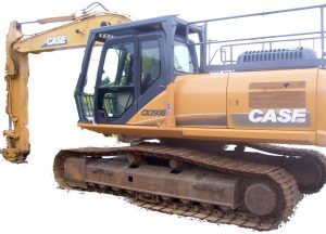
Case CX290 Crawler Excavators Workshop Repair & Service Manual


Case CX290

MCSCX290OPES.zip
Price: $29.99 USD

Complete digital official shop manual contains service, maintenance, and troubleshooting information for the Case CX290 Crawler Excavators. Diagnostic and repair procedures are covered in great detail to repair, maintain, rebuild, refurbish or restore your Case CX290 Crawler Excavators like a professional mechanic in local service/repair workshop. This cost-effective quality manual is 100% complete and intact as should be without any missing pages. It is the same factory shop manual used by dealers that guaranteed to be fully functional to save your precious time.

This manual for Case CX290 Crawler Excavators is divided into different sections. Each section covers a specific component or system and, in addition to the standard service procedures, includes disassembling, inspecting, and assembling instructions. A table of contents is placed at the beginning of each section. Pages are easily found by category, and each page is expandable for great detail. It is in the cross-platform PDF document format so that it works like a charm on all kinds of devices. You do not need to be skilled with a computer to use the manual.

“9-53581.pdf”
Case CX290 Crawler Excavators Service Manual
607 pages

EXCERPT:
Table of contents
1 GENERAL INFORMATION
Table of contents
Safety, general information and standard torque data ………. 1001
General specifications and special torque setting …….. 1 002
2 ENGINE
Removal and installation of the engine …… 2000
Radiator and oil-cooler …………. 2001
Engine specifications ………… *
Disassembly and assembly of the engine …….. *
3 FUEL SYSTEM
Fuel tank ……………. 3001
Fuel engine system …… *
4 ELECTRICAL SYSTEM
Electrical system, electrical and electronic troubleshooting ………. .4001
Inspection and maintenance of batteries and connecting a booster battery … .4002
Main and engine electronic control boxes ……….4003
5 UNDERCARRIAGE
Removal and installation of tracks …………. 5001
Rollers ……….. 5003
Sprocket …………….. 5004
Idler wheel and tension shock absorber …………. 5005
6 DRIVE TRAIN
Drive motor and final drive transmission removal and installation ………. 6001
Swing reduction gear, removal and installation … 6003
Swing reduction gear, disassembly and assembly ……. 6004
Travel reduction gear assembly and disassembly …….. 6005
7 UNDER-CARRIAGE HYDRAULICS
8 UPPER-STRUCTURE HYDRAULICS
Depressurizing and decontaminating the hydraulic system, use of the vacuum pump and bleeding the components ………. 8000
Specifications, troubleshooting, checks and hydraulic pressure settings ……… 8001
Hydraulic reservoir removal and installation ……. 8002
Main and pilot pumps, removal and installation ……….. 8003
Main hydraulic control valve, removal and installation ………. 8004
Attachment cylinders, removal and installation … 8005
Hydraulic swivel, removal and installation ……….. 8006
Pilot blocs, removal and installation ……….. 8007
Swing motor, removal and installation …….. 8008
Free swing disassembly and assembly …… 8009
Main hydraulic pump, disassembly and assembly ……. 8010
Main hydraulic control valve, disassembly and assembly ….. 8011
Attachment cylinders, disassembly and assembly ……. 8012
Hand control levers, disassembly and assembly ……… 8013
Foot control levers, disassembly and assembly ……….. 8014
Six-solenoid valves, disassembly and assembly ………. 8015
Caution valve, disassembly and assembly ………. 8016
Safety valve ………… 8017
Hydraulic swivel, disassembly and assembly …… 8018
Swing motor, disassembly and assembly ……….. 8019
Hydraulic functions ………. 8020
Travel hydraulic motor, disassembly and assembly …… 8021
9 UPPERSTRUCTURE
Upper-structure, turntable and counterweight …… 9002
Boom, dipper and bucket ……… 9003
Seat and seat belt ……….. 9004
Cab and cab equipment ……….. 9005
Air conditioner troubleshooting and system checks ….. 9006
Air conditioning unit disassembly and assembly ………. 9007
Air conditioning servicing ……… 9008
Air conditioning components …………. 9009
Attachment reinforcement procedures ……. 9012
Large format hydraulic and electrical schematics ….. Pocket

MAIN CONTROL VALVE
Removal and installation
STEP 1
Park the machine on hard, flat ground. Lower the attachment to the ground.
STEP 2
Release pressure in the hydraulic system and in the hydraulic reservoir (see Section 8000).
STEP 3
Disconnect the earth (-) cable (1) from the battery.
STEP 4
To prevent any fluid leaks when disconnecting hydraulic lines, connect a vacuum pump to the hydraulic reservoir (see Section 8000).
STEP 5
Remove the retaining screws from the upper access door (1) then remove the door.
NOTE: When installing, tighten the screws to a torque of 65 to 79 lb-ft (apply Loctite 262 to the
threads).
STEP 6
Remove the retaining screws from the central frame (1) then remove the central frame.
NOTE: When installing, tighten the screws to a torque of 65 to 79 lb-ft (apply Loctite 262 to the threads).
STEP 7
CD00F116
Remove the screws (1) then remove the clamp (2).
STEP 8
Start the vacuum pump.
STEP 9
Remove the two retaining clips (1) from the hose (2) then remove the hose from the manifold.
STEP 10
Remove the retaining screws (1) from the clamp (2).
STEP 11
Attach identification tags to all hoses, pipes and electrical wires of the control valve. Disconnect and seal the hoses and pipes. Seal the control valve ports.
Disconnect the electrical connections.
STEP 12
Stop the vacuum pump.
STEP 13
Install lifting rings in the threaded orifices on the top of the control valve.
STEP 14
Connect a suitable lifting device to the control valve.
See Section 1002 for the weight of the control valve.
STEP 15
Remove the retaining screws (1) and washers from the control valve.
NOTE: When installing, tighten the screws to the torque specified in Section 1002.
STEP 16
Carefully raise and guide the control valve out of the upper-structure frame. Move all the hoses and pipesout of the way. Remove the control valve from the machine and place it on suitable stands.
NOTE: The following step is to be performed only if the control valve has to be changed.
STEP 17
Remove the unions and manifolds from the control valve which has just been removed and mount them on the new control valve. Remove and install the unions and manifolds one after another to make sure that they are correctly installed on the new control valve.
NOTE: When installing, follow the same procedure in the reverse order. Replace all seals with new seals.
NOTE: Before carrying out any work with the machine, operate the swing, travel and the attachment for five minutes with the engine at idle speed.
Check that there are no leaks in the system, check the level of oil in the hydraulic reservoir, top up if necessary.
Adjust the valves in the control valve (see Section 8001).