Pages from 9803-3690 – JCB Compact Loadalls (520-40, 524-50, 527-55) Service Manual
Complete workshop & service manual with electrical wiring diagrams for JCB Loadall (520-40, 520-50, 524-50, 525-50, 525-50S, 520-55 RS, 520-55 AWS, 526-55, 526-55 AWS, 526S AWS, 527-55). It’s the same service manual used by dealers that guaranteed to be fully functional and intact without any missing page.
This JCB Loadall (520-40, 520-50, 524-50, 525-50, 525-50S, 520-55 RS, 520-55 AWS, 526-55, 526-55 AWS, 526S AWS, 527-55) service & repair manual (including maintenance, overhaul, disassembling & assembling, adjustment, tune-up, operation, inspecting, diagnostic & troubleshooting…) is divided into different sections. Each section covers a specific component or system with detailed illustrations. A table of contents is placed at the beginning of each section. Pages are easily found by category, and each page is expandable for great detail. The printer-ready PDF documents work like a charm on all kinds of devices.
FILELIST:
9803-3610 – JCB Loadall (520-55 RS/AWS, 526-55, 526-55 AWS, 526S AWS) Service Manual.pdf
9803-3620 – JCB Loadall (520-50, 525-50, 525-50S) Service Manual.pdf
9803-3690 – JCB Compact Loadalls (520-40, 524-50, 527-55) Service Manual .pdf
Loadalls 2000_2010 Electrical Wiring Diagrams (BONUS MATERIAL).pdf
EXCERPT:
Service Manual
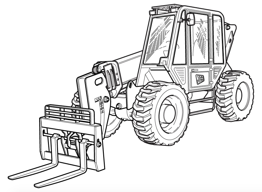
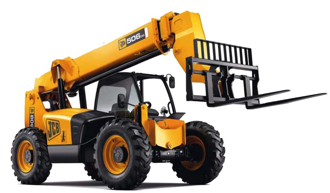
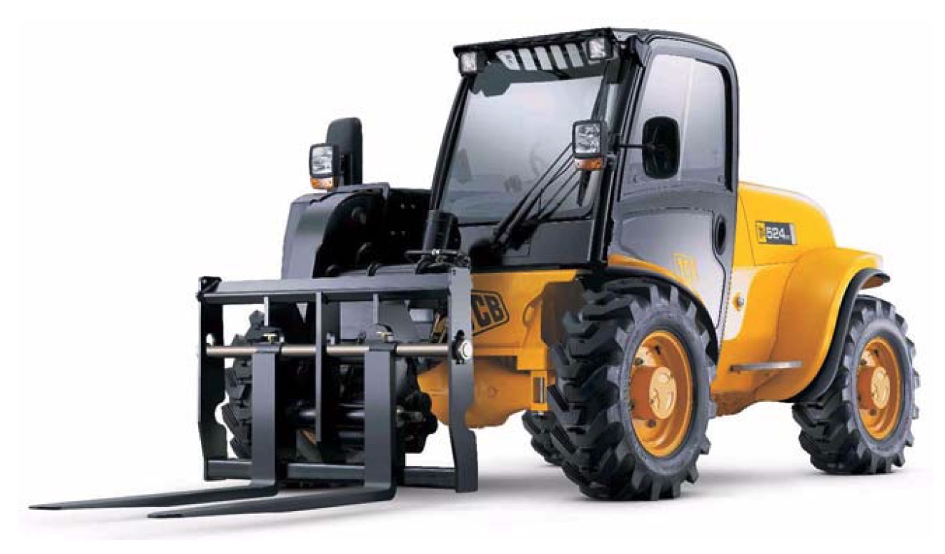
Compact Loadalls
Section 1 – General Information
Section 2 – Care and Safety
Section 3 – Maintenance
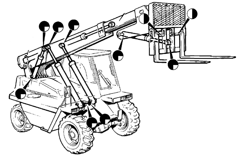
Section A – Attachments
Section B – Body and Framework
Section C – Electrics
Section D – Controls
Section E – Hydraulics
Section F – Transmissions
Section G – Brakes
Section H – Steering
Section K – Engine
…
Fire Extinguisher (if fitted)
Checking the Fire Extinguisher
Check the fire extinguisher for damage, security and signs of leaking.
Check that the gauge A indicates that the extinguisher is charged i.e. the needle is in the GREEN segment.
Note: If the needle is in or very near the RED segment at either end of the gauge, the extinguisher must be serviced or replaced.
Make sure the safety pin B is fitted and secure.
The extinguisher should be serviced every 12 months by a suitably qualified person.
…