Posted on

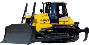
New Holland D180 Crawler Dozer Factory Service & Shop Manual


New Holland D180

MNHD180OPES.zip
Price: $29.99 USD

Complete workshop & service manual with electrical wiring diagrams for New Holland D180 Crawler Dozer. It’s the same service manual used by dealers that guaranteed to be fully functional and intact without any missing page.

This New Holland D180 Crawler Dozer service & repair manual (including maintenance, overhaul, disassembling & assembling, adjustment, tune-up, operation, inspecting, diagnostic & troubleshooting…) is divided into different sections. Each section covers a specific component or system with detailed illustrations. A table of contents is placed at the beginning of each section. Pages are easily found by category, and each page is expandable for great detail. The printer-ready PDF documents work like a charm on all kinds of devices.

“604.13.522.00.pdf”
New Holland D180 Crawler Dozer Worksop Manual
Print No. Print No. 604.13.522.00 English
417 pages

SUMMARY
GENERALITIES SECT. 0
ENGINE SECT. 1
TRANSMISSION SECT. 2
FINAL DRIVES SECT. 3
BRAKES AND STEERING DIFFERENTIAL – D180 POWER STEERING SECT. 4
BRAKES AND STEERING CLUTCHES – D180 STEERING CLUTCHES SECT. 4 BIS
UNDERCARRIAGE SECT. 5
DOZING EQUIPMENT – HYDRAULIC SYSTEM D180 PS SECT. 6
DOZING EQUIPMENT – HYDRAULIC SYSTEM D180 SC SECT. 6 BIS
ELECTRICAL SYSTEM SECT. 7
AIR CONDITIONING UNIT SECT. 8

EXCERPT:
BRAKES AND STEERING CLUTCHES
Re-installation of brake/steering differential group into the transmission housing.
WARNING
Never use gasoline, solvents or any other flammable fluid to clean components. Use approved commercial non flammable and non toxic solvents only.
WARNING
Use appropriate tools to align holes. NEVER USE FINGERS OR HANDS.
Lift the brake/differential group using a hoist and special tool P/N 380001348.
Lubricate adequately al mating parts of the assembly and the housing.
WARNING
Clean accurately the faces of the group mating the transmission housing.
Insert the two centering guides, special tool 380001484 on the housing, to facilitate the engaging of the steering brakes assembly.
Approach the brakes/steering group into the transmission housing, taking care that the components are not damaged.
Make sure that the gears are matching appropriately.
Install a few screws and tighten them slowly, to ensure an appropriate setting of the brake group.
Install the remaining screws C2 and tighten them alternatively and diagonally, to ensure a uniform tightening (Screws C2 tightening torque 11 daNm).
To complete the re-assembly operation, please refer to item 4.4.3 (preliminary operations) reversing the procedure described.

Posted on

New Holland CX5080, CX5090, CX6080, CX6090 Elevation/Laterale/Hillside Combine Factory Service & Shop Manual


New Holland CX5080, CX5090, CX6080, CX6090


INSTANT DOWNLOAD


Complete workshop & service manual with electrical wiring diagrams for New Holland CX5080, CX5090, CX6080, CX6090 Elevation/Laterale/Hillside Combine. It’s the same service manual used by dealers that guaranteed to be fully functional and intact without any missing page.

This New Holland CX5080, CX5090, CX6080, CX6090 Elevation/Laterale/Hillside Combine service & repair manual (including maintenance, overhaul, disassembling & assembling, adjustment, tune-up, operation, inspecting, diagnostic & troubleshooting…) is divided into different sections. Each section covers a specific component or system with detailed illustrations. A table of contents is placed at the beginning of each section. Pages are easily found by category, and each page is expandable for great detail. The printer-ready PDF documents work like a charm on all kinds of devices.

“47824864.pdf”
New Holland CX5080 Elevation / CX5090 Elevation / CX5090 Laterale / CX5090 Hillside / CX6080 Elevation / CX6090 Elevation / CX6090 Laterale Combine Service Manual
Part number 47824864 English February 2015
3,203 pages

SERVICE MANUAL
CX5000 Elevation series Tier IV
CX6000 Elevation series Tier IV

CX5090 Laterale Asia Pacific F4HFE613T*A005
CX5080 Elevation Europe F4HFE613U*A005
CX5090 Elevation Europe F4HFE613T*A005
CX5090 Laterale Middle East Africa F4HFE613T*A005
CX5090 Hillside Europe F4HFE613T*A005
CX5090 Laterale Europe F4HFE613T*A005
CX6090 Laterale Asia Pacific F2CFE613L*A
CX6090 Elevation Europe F2CFE613L*A
CX6090 Laterale Middle East Africa F2CFE613L*A
CX6080 Elevation Europe F4HFE613T*A005
CX6090 Laterale Europe F2CFE613L*A

EXCERPT:

Steering – Steering control

Steering column – Remove

1. Pull off the adjusting knob (1). Remove the screws (2) and take the upper cover halves from the steering column.

2. Pull the left-hand side upper cover over the direction indicator lever.

3. Lower the boot (3) to have access to the lower screw of the cover. Remove the two screws (4) of the both lower cover halves.

4. With the covers removed, all internal steering column components can be accessed.

Steering column – Install

1. Position the two lower halves of the steering column covers and install the screws (4). Secure the boot (3) to the lower cover halves.

2. Position the two upper cover halves of the steering column and don’t forget to install the switch (5) and the light indicator (6) between the cover halves.

3. Install and tighten the two screws (2). Install the adjusting knob (1).


INSTANT DOWNLOAD


Posted on

New Holland CX720, CX740, CX760, CX780, CX820, CX840, CX860, CX880 Combines Factory Service & Shop Manual


New_Holland_CX720-780_CX820-880

MNHCX720CX880OPEK.zip
Price: $29.99 USD

Complete workshop & service manual for New Holland CX720, CX740, CX760, CX780, CX820, CX840, CX860, CX880 Combines. It’s the same service manual used by dealers that guaranteed to be fully functional and intact without any missing page.

This New Holland CX720, CX740, CX760, CX780, CX820, CX840, CX860, CX880 Combines service & repair manual (including maintenance, overhaul, disassembling & assembling, adjustment, tune-up, operation, inspecting, diagnostic & troubleshooting…) is divided into different sections. Each section covers a specific component or system with detailed illustrations. A table of contents is placed at the beginning of each section. Pages are easily found by category, and each page is expandable for great detail. The printer-ready PDF documents work like a charm on all kinds of devices.

“6043400100 – CX720, CX740, CX760, CX780, CX820, CX840, CX860, CX880 Repair Manual.pdf”
4,282 PAGES

Contents
INTRODUCTION
DISTRIBUTION SYSTEMS A
PRIMARY HYDRAULIC POWER SYSTEM A.10.A
SECONDARY HYDRAULIC POWER SYSTEM A.12.A
HYDRAULIC COMMAND SYSTEM A.14.A
PNEUMATIC SYSTEM A.20.A
ELECTRICAL POWER SYSTEM A.30.A
LIGHTING SYSTEM A.40.A
ELECTRONIC SYSTEM A.50.A
POWER PRODUCTION B
ENGINE B.10.A
FUEL AND INJECTION SYSTEM B.20.A
AIR INTAKE SYSTEM B.30.A
EXHAUST SYSTEM B.40.A
ENGINE COOLANT SYSTEM B.50.A
LUBRICATION SYSTEM B.60.A
STARTING SYSTEM B.80.A
POWER TRAIN C
POWER COUPLING Fixed coupling C.10.B
TRANSMISSION Mechanical C.20.B
TRANSMISSION Hydrostatic C.20.F
PROCESS DRIVE Primary process drive C.50.B
TRAVELLING D
FRONT AXLE D.10.A
REAR AXLE D.12.A
2WD-4WD SYSTEM Hydrostatic D.14.E
STEERING Hydraulic D.20.C
SERVICE BRAKE Hydraulic D.30.C
PARKING BRAKE Hydraulic D.32.C
BODY AND STRUCTURE E
SHIELD E.20.A
OPERATOR AND SERVICE PLATFORM E.30.A
USER CONTROLS AND SEAT E.32.A
USER CONTROLS AND SEAT Operator seat E.32.C
USER PLATFORM E.34.A
ENVIRONMENT CONTROL Heating system E.40.B
ENVIRONMENT CONTROL Air-conditioning system E.40.C
ENVIRONMENT CONTROL Heating, ventilation and air-conditioning E.40.D
SAFETY SECURITY ACCESSORIES Safety E.50.B
TOOL POSITIONING G
LIFTING G.10.A
LEVELLING G.30.A
CROP PROCESSING K
FEEDING Reel feeding K.25.B
FEEDING Header feeding K.25.D
FEEDING Feeder housing K.25.E
THRESHING Conventional threshing K.40.B
SEPARATING Beating K.42.B
SEPARATING Rotary separator K.42.C
SEPARATING Straw walker K.42.E
SEPARATING Straw flow beater K.42.F
STORING AND HANDLING Grain storing K.60.B
CLEANING Primary cleaning K.62.B
CLEANING Tailings return system K.62.C
RESIDUE HANDLING Straw chopper K.64.C
RESIDUE HANDLING Spreader K.64.D
RESIDUE HANDLING Chaff blower K.64.F
UNLOADING Grain unloading K.72.B

EXCERPT:
TRAVELLING – REAR AXLE
Steering knuckle – Assemble (D.12.A.69 – F.10.A.20)
1. Using the locally fabricated tool, insert the bushing (1) and press into place until there is a maximum of 3mm(0.118 in) gap at the bottom of the bore. Apply a generous coating of grease to the bushing and fill the area above with the same grease. Install the seal (2) with the cupped side up.
2. Using the locally fabricated tool, insert the bushing (1) and press into place until there is a maximum of 3mm(0.118 in) gap at the bottom of the bore. Apply a generous coating of grease to the bushing and fill the area above with the same grease. Install the seal (2) with the cupped side up.
3. Inspect the machined ends (1) of the steering knuckle for wear, scratches and gouges. If the knuckle exhibits excessive play when assembled, replace the knuckle.

Posted on

New Holland CSX7040, CSX7050, CSX7060, CSX7070, CSX7080 Combine Harvesters Factory Service & Shop Manual


Pages from 84210989A – CSX7040, CSX7050, CSX7060, CSX7070, CSX7080 Service Manual.pdf

INSTANT DOWNLOAD

Complete workshop & service manual with electrical wiring diagrams for New Holland CSX7040, CSX7050, CSX7060, CSX7070, CSX7080 Combine Harvesters. It’s the same service manual used by dealers that guaranteed to be fully functional and intact without any missing page.

This New Holland CSX7040, CSX7050, CSX7060, CSX7070, CSX7080 Combine Harvesters service & repair manual (including maintenance, overhaul, disassembling & assembling, adjustment, tune-up, operation, inspecting, diagnostic & troubleshooting…) is divided into different sections. Each section covers a specific component or system with detailed illustrations. A table of contents is placed at the beginning of each section. Pages are easily found by category, and each page is expandable for great detail. The printer-ready PDF documents work like a charm on all kinds of devices.

84210989A – CSX7040, CSX7050, CSX7060, CSX7070, CSX7080 Service Manual.pdf – 1,650 pages

MAIN SECTIONS
INTRODUCTION
DISTRIBUTION SYSTEMS……….. A
PRIMARY HYDRAULIC POWER SYSTEM . . . . . A.10.A
PNEUMATIC SYSTEM . . . . A.20.A
ELECTRICAL POWER SYSTEM . . . . . A.30.A
LIGHTING SYSTEM. . . . . . . A.40.A
ELECTRONIC SYSTEM . . . . A.50.A
FAULT CODES . . . . A.50.A
POWER PRODUCTION ….. B
ENGINE . . . B.10.A
EXHAUST SYSTEM. . . . . . . B.40.A
ENGINE COOLANT SYSTEM . . . . . . B.50.A
STARTING SYSTEM . . . . . . B.80.A
AIR INTAKE SYSTEM . . . . . B.30.A
POWER TRAIN …….C
TRANSMISSION Mechanical . . . . . . . C.20.B
TRANSMISSION Hydrostatic. . . . . . C.20.F
PROCESS DRIVE Primary process drive . . . . . C.50.B
TRAVELLING……….D
FRONT AXLE . . . . . D.10.A
REAR AXLE . . . . . D.12.A
2WD-4WD SYSTEM Hydrostatic . . . . D.14.E
STEERING Hydraulic. . . . . D.20.C
STEERING Mechanical . . . . . D.20.B
SERVICE BRAKE Hydraulic. . . . . . D.30.C
PARKING BRAKE Mechanical . . . . . . D.32.B
BODY AND STRUCTURE ………… E
USER CONTROLS AND SEAT . . . . . E.32.A
USER PLATFORM . . . . . . E.34.A
ENVIRONMENT CONTROL Heating system . . . E.40.B
ENVIRONMENT CONTROL Air-conditioning system . . . . . E.40.C
ENVIRONMENT CONTROL Heating, ventilation and air-conditioning. . . . . . E.40.D
SAFETY SECURITY ACCESSORIES Safety . . . E.50.B
FRAME POSITIONING …… F
FRAME LEVELLING . . . . . . F.30.A
TOOL POSITIONING …….. G
LIFTING . . . . . . G.10.A
LEVELLING . . . . G.30.A
CROP PROCESSING …….. K
FEEDING Reel feeding. . . . K.25.B
FEEDING Header feeding. . . K.25.D
FEEDING Feeder housing . . K.25.E
THRESHING Conventional threshing . . . K.40.B
SEPARATING Beating. . . . . K.42.B
SEPARATING Rotary separator . . . . . K.42.C
SEPARATING Straw flow beater . . . . K.42.F
SEPARATING Straw walker . . . K.42.E
CLEANING Primary cleaning. . . . . . K.62.B
CLEANING Tailings return system . . . . K.62.C
STORING AND HANDLING Grain storing . . . . K.60.B
UNLOADING Grain unloading. . . . . . . K.72.B

INSTANT DOWNLOAD

Posted on

New Holland CR6.80, CR6.90, CR7.90, CR8.80, CR8.90, CR9.80, CR9.90, CR10.90 Combine Factory Service & Shop Manual

New Holland CR6.80, CR6.90, CR7.90, CR8.80, CR8.90, CR9.80, CR9.90, CR10.90

MNHCRVIXOPES.zip
Price: $29.99 USD

Complete workshop & service manual with electrical wiring diagrams for New Holland CR6.80, CR6.90, CR7.90, CR8.80, CR8.90, CR9.80, CR9.90, CR10.90 Combine. It’s the same service manual used by dealers that guaranteed to be fully functional and intact without any missing page.

This New Holland CR6.80, CR6.90, CR7.90, CR8.80, CR8.90, CR9.80, CR9.90, CR10.90 Combine service & repair manual (including maintenance, overhaul, disassembling & assembling, adjustment, tune-up, operation, inspecting, diagnostic & troubleshooting…) is divided into different sections. Each section covers a specific component or system with detailed illustrations. A table of contents is placed at the beginning of each section. Pages are easily found by category, and each page is expandable for great detail. The printer-ready PDF documents work like a charm on all kinds of devices.

“47865347.pdf”
New Holland CR6.80, CR6.90, CR7.90, CR8.90, CR9.90 T4B (final) Combine Service Manual
Part number 47865347 1st edition English April 2015
6,584 pages

CR6.80 TIER 4B North America F2CFE613C*B006
CR6.90 TIER 4B North America F2CFE613C*B006
CR7.90 TIER 4B North America F2CFE613A*B
CR8.90 TIER 4B North America F3GFE613B*B001
CR9.90 TIER 4B North America F3HFE613A*B003

— — — — — — — — — — — — — — — — — — — — — — — —

“47869937.pdf”
New Holland CR7.90, CR8.80, CR8.90, CR9.80, CR9.90, CR10.90 Combine Service Manual
Part number 47869937 English April 2015
5,779 pages

CR10.90 TIER 4B [1947 – ] , CR10.90 TIER 4B tracks [1947 – ] , CR10.90 TIER 4B tracks [1947 – ] , CR7.90 TIER 3 [1946 – ] , CR7.90 TIER 4A [1946 – ] , CR7.90 TIER4A [1946 – ] , CR8.80 TIER 3 [1946 – ] , CR8.80 TIER 4A [1946 – ] , CR8.80 TIER 4A tracks [1946 – ] , CR8.90 TIER 4A [1946 – ] , CR8.90 TIER 4A tracks [1946 – ] , CR8.90 TIER4A [1946 – ] , CR8.90 TIER4A tracks [1946 – ] , CR9.80 TIER 3 [1961 – ] , CR9.80 TIER 3 tracks [1946 – ] , CR9.80 TIER 4A 3 axle [1946 – ] , CR9.80 TIER 4A [1946 – ] , CR9.80 TIER 4A tracks [1946 – ] , CR9.90 TIER 4A 3 axle [1947 – ] , CR9.90 TIER 4A [1947 – ] , CR9.90 TIER 4A [1954 – ] , CR9.90 TIER 4A tracks [1947 – ] , CR9.90 TIER4A [1947 – ] , CR9.90 TIER4A [1954 – ] , CR9.90 TIER4A tracks [1947 – ]

CR10.90 TIER 4B tracks [1947 – ] Europe F3JFE613A*B004
CR10.90 TIER 4B [1947 – ] Australia New Zealand F3JFE613A*B004
CR10.90 TIER 4B tracks [1947 – ] Australia New Zealand F3JFE613A*B004
CR7.90 TIER 4A [1946 – ] Europe F2CFE613A*A
CR7.90 TIER4A [1946 – ] Australia New Zealand F2CFE613A*A
CR8.80 TIER 4A [1946 – ] Europe F3AFE613A*A
CR8.80 TIER 4A tracks [1946 – ] Europe F3AFE613A*A
CR8.90 TIER 4A [1946 – ] Europe F3AFE613A*A
CR8.90 TIER 4A tracks [1946 – ] Europe F3AFE613A*A
CR8.90 TIER4A [1946 – ] Australia New Zealand F3AFE613A*A
CR8.90 TIER4A tracks [1946 – ] Australia New Zealand F3AFE613A*A
CR9.80 TIER 4A [1946 – ] Europe F3BFE613E*A
CR9.80 TIER 4A tracks [1946 – ] Europe F3BFE613E*A
CR9.80 TIER 4A 3 axle [1946 – ] Europe F3BFE613E*A
CR9.90 TIER 4A [1947 – ] Europe F3BFE613D*A
CR9.90 TIER 4A tracks [1947 – ] Europe F3BFE613D*A
CR9.90 TIER 4A 3 axle [1947 – ] Europe F3BFE613D*A
CR9.90 TIER4A [1947 – ] Australia New Zealand F3BFE613D*A
CR9.90 TIER4A tracks [1947 – ] Australia New Zealand F3BFE613D*A
CR9.90 TIER4A [1954 – ] Europe F3BFE613D*A
CR9.90 TIER 4A [1954 – ] Europe F3BFE613D*A

EXCERPT:
Steering – Hydraulic control components
Hydraulic control components – Test
CR10.90 WE
CR7.90 WE —
CR8.80 WE —
CR8.90 WE —
CR9.80 WE —
CR9.90 WE —
1. The following practical test will determine if steering pump output is sufficient to allow satisfactory operation of the steering system.
Steering Test
2. Set engine speed to high idle
3. Turn steering quickly from lock to lock.
If steering is operating correctly the reaction should be immediate with no time delay between turning the steering wheel and movement of the wheels.
4. At full lock the relief valve in the main frame valve stack should be heard to blow.
5. Steering Circuit Pressure Test
6. Install Tee adaptor (3) Parker fitting 8R6MLOS and quick release adaptor (2) Parker fitting PD38BTL, into hose to steering cylinder.
7. Connect 0-250 bar ( 0-3600 psi) pressure gauge (1) 293244, with hose 292246, using quick release coupler 291924.
8. Set engine speed to high idle.
9. Turn steering wheel to full lock and hold in position.
10. Pressure reading of approximately 175 bar (2538 psi) should be recorded.

Steering circuit relief valve – Test
CR10.90 WE
CR7.90 WE —
CR8.80 WE —
CR8.90 WE —
CR9.80 WE —
CR9.90 WE —
1. Turn steering onto full left hand lock.
2. Disconnect the left hand turn feed hose.
3. Install an elbow (1) Parker fitting 8 ELOS (13/16 UNFORFS) with quick release adaptor (2) parker fitting PD38BTL.
4. Connect 0-250 bar ( 0-3600 psi) pressure gauge 293244 (3) with hose 292246, using quick release coupler 291924.
5. Start the engine and set to high idle speed. Turn steering wheel to the left with a pull of approximately 22 N (2.25 kgf , 5 lbf) and observe the pressure reading.
If the steering test was satisfactory but the pressure readings are away from specification the relief valve in the main frame stack, priority valve slice must be adjusted.
The pressure reading should be:-175 bar ( 2538 psi) for all models.
NOTE: The use of a force greater than 5 lbf. at the rim of the steering wheel may lead to slightly inaccurate readings due to the pumping action of the hydrostatic steering motor.