Posted on

New Holland CL560, CS520, CS540, CS640, CS660 Combines Factory Service & Shop Manual


New Holland CL560, CS520, CS540, CS640, CS660

MNHCLCSOPES.zip
Price: $29.99 USD

Complete workshop & service manual with electrical wiring diagrams for New Holland CL560, CS520, CS540, CS640, CS660 Combines. It’s the same service manual used by dealers that guaranteed to be fully functional and intact without any missing page.

This service & repair manual (including maintenance, overhaul, disassembling & assembling, adjustment, tune-up, operation, inspecting, diagnostic & troubleshooting…) is divided into different sections. Each section covers a specific component or system with detailed illustrations. A table of contents is placed at the beginning of each section. Pages are easily found by category, and each page is expandable for great detail. The printer-ready PDF documents work like a charm on all kinds of devices.

“6043401100.pdf”
New Holland CL560, CS520, CS540, CS640, CS660 Combines Repair Manual
604_34_011_00 5 27/05/2005
2,446 pages

Contents
INTRODUCTION
DISTRIBUTION SYSTEMS A
POWER PRODUCTION B
POWER TRAIN C
TRAVELLING D
BODY AND STRUCTURE E
FRAME POSITIONING F
TOOL POSITIONING G
CROP PROCESSING K

EXCERPT:

BODY AND STRUCTURE – ENVIRONMENT CONTROL Heating system

ENVIRONMENT CONTROL Heating system – Check (E.40.B – F.45.A.10)
CS540, CS640, CS520, CS660, CL560
1. Check that both engine coolant shutoff valves at the engine block are open.
(CCW = Open, CW = Closed)
2. Check that the heater supply hose at the rear of the engine head is warm.
3. Check that the engine coolant temperature is at least 76 ° C (170 ° F).
4. Check the cab fresh air filter to check that it is clean and free from obstruction to air flow.
5. Check the cab recirculation air filter to see that it is clean and free from obstruction to air flow.

BODY AND STRUCTURE – E
ENVIRONMENT CONTROL Heating system – 40.B
ENVIRONMENT CONTROL Heating system – Check (E.40.B – F.45.A.10)
CS540, CS640, CS520, CS660, CL560

Posted on

New Holland Skid Steer Loader/ Compact Track Loader C227, C232, C238, L213, L215, L218, L220, L223, L225, L230 Factory Service & Shop Manual


New Holland C227, C232, C238, L213, L215, L218, L220, L223, L225, L230


INSTANT DOWNLOAD


Complete workshop & service manual with electrical wiring diagrams for New Holland Skid Steer Loader/ Compact Track Loader C227, C232, C238, L213, L215, L218, L220, L223, L225, L230. It’s the same service manual used by dealers that guaranteed to be fully functional and intact without any missing page.

This New Holland Skid Steer Loader/ Compact Track Loader C227, C232, C238, L213, L215, L218, L220, L223, L225, L230 service & repair manual (including maintenance, overhaul, disassembling & assembling, adjustment, tune-up, operation, inspecting, diagnostic & troubleshooting…) is divided into different sections. Each section covers a specific component or system with detailed illustrations. A table of contents is placed at the beginning of each section. Pages are easily found by category, and each page is expandable for great detail. The printer-ready PDF documents work like a charm on all kinds of devices.

84423865 – Skid Steer Loader (L213_L215_L218_L220 L223_L225_L230) & Compact Track Loader (C227_C232_C238) 200 Series Service Manual.pdf
84522361 – 200-Series Skid Steer Loader L213, L215, L218, L220 L223, L225, L230 & Compact Track Loader C227, C232, C238 Service Manual.pdf

— — — — — — — — — — — — — — — — — — — — — — — —

EXCERPT:

HITCH AND WORKING TOOL – SINGLE ARM Lift

WARNING: Heavy objects! Lift and handle all heavy components using lifting equipment with adequate capacity. Always support units or parts with suitable slings or hooks. Make sure the work area is clear of all bystanders. Failure to comply could result in death or serious injury.

Prior operation: SINGLE ARM Lift – Remove single lift arm (H.40.B)]

1. Using appropriate lifting device and straps raise lift arm into proper location on the unit.

2. Install left hand side and right hand side lift arm pins (1).

3. Install left hand side and right hand side lift arm retaining bolts (1).

4. Reposition lifting device and straps and raise lift arm (1).

5. Raise cylinders (1) up.

6. Insert cylinders into arm and secure with rod end pins and washers (1).
NOTE: Right hand side has lock out.

7. Install rod end snap rings (1).


INSTANT DOWNLOAD


Posted on

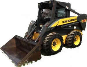
New Holland L180, L185, L190 Skid Steer Loader, C185, C190, Compact Track Loader Factory Service & Shop Manual

New Holland C185, C190, L180, L185, L190

MNH180190CLOPEK.zip
Price: $29.99 USD

Complete workshop & service manual with electrical wiring diagrams for New Holland L180, L185, L190 Skid Steer Loader, C185, C190, Compact Track Loader. It’s the same service manual used by dealers that guaranteed to be fully functional and intact without any missing page.

This New Holland L180, L185, L190 Skid Steer Loader, C185, C190, Compact Track Loader service & repair manual (including maintenance, overhaul, disassembling & assembling, adjustment, tune-up, operation, inspecting, diagnostic & troubleshooting…) is divided into different sections. Each section covers a specific component or system with detailed illustrations. A table of contents is placed at the beginning of each section. Pages are easily found by category, and each page is expandable for great detail. The printer-ready PDF documents work like a charm on all kinds of devices.

“84522361.pdf”
New Holland L180, L185, L190 Skid Steer Loader, C185, C190, Compact Track Loader Mechanical and Pilot Control (Cab Upgrade Machines) Repair Manual
87630288 NA Replaces 87578815 NA
Issued 12-2006 Revised 05-2007
1,068 pages

CONTENTS
INTRODUCTION
DISTRIBUTION SYSTEMS
PRIMARY HYDRAULIC POWER SYSTEM SECONDARY HYDRAULIC POWER SYSTEM HIGH­FLOW HYDRAULIC POWER SYSTEM ELECTRICAL POWER SYSTEM
LIGHTING SYSTEM
POWER PRODUCTION ENGINE
FUEL AND INJECTION SYSTEM AIR INTAKE SYSTEM
ENGINE COOLANT SYSTEM LUBRICATION SYSTEM STARTING SYSTEM
POWER TRAIN
POWER COUPLING Fixed coupling
TRANSMISSION Hydrostatic
TRAVELLING
FRONT AXLE
REAR AXLE
STEERING Steering clutch
PARKING BRAKE Hydraulic
WHEELS AND TRACKS Tracks WHEELS AND TRACKS Wheels Final drive
BODY AND STRUCTURE USER CONTROLS AND SEAT USER PLATFORM
ENVIRONMENT CONTROL Heating system
ENVIRONMENT CONTROL Air-conditioning system SAFETY SECURITY ACCESSORIES Safety
WORKING ARM
SINGLE ARM Lift
SINGLE ARM TOOL ATTACHMENT Tilt
TOOLS AND COUPLERS CARRYING Unarticulated tools COUPLING Hydraulic coupling
COUPLING Mechanical coupling

— — — — — — — — — — — — — — — — — — — — — — — —

EXCERPT:
POWER TRAIN ­ TRANSMISSION Hydrostatic
Pump Right hand pump ­ Measure
1. Measure the free travel between the shoes and the pistons. If all the measurements are not equal to within 0.13 mm (0.005 in), use a new cylinder as­sembly.
2. Measure the thickness of each shoe. If the measure­ments are not equal to within 0.02 mm (0.0001 in), use a new cylinder assembly.
3. Check the fit of the pistons in the bores. The piston must move freely with minimum clearance. Use a new cylinder assembly as necessary.
4. Measure the gear tip clearance between the inner gear and the outer gear. Clearance must not be more than 0.13 mm (0.005 in).
5. Measure the width of the inner gear and the outer gear. The width of each gear must be equal to within 0.05 ­ 0.06 mm (0.002 ­ 0.003 in).

Posted on

New Holland C175, L175 Skid Steer Factory Service & Shop Manual

New Holland C175, L175

MNH175CLOPEK.zip
Price: $29.99 USD

Complete workshop & service manual with electrical wiring diagrams for New Holland C175, L175 Skid Steer (Compact Track Loader). It’s the same service manual used by dealers that guaranteed to be fully functional and intact without any missing page.

This New Holland C175, L175 Skid Steer (Compact Track Loader) service & repair manual (including maintenance, overhaul, disassembling & assembling, adjustment, tune-up, operation, inspecting, diagnostic & troubleshooting…) is divided into different sections. Each section covers a specific component or system with detailed illustrations. A table of contents is placed at the beginning of each section. Pages are easily found by category, and each page is expandable for great detail. The printer-ready PDF documents work like a charm on all kinds of devices.

“87630289.pdf”
New Holland C175, L175 Skid Steer (Compact Track Loader) Workshop Manual
Print No. 87630289
967 pages

C175, L175 REPAIR MANUAL TABLE OF CONTENTS
SECTION 00 – GENERAL INFORMATION SECTION 10 – ENGINE
SECTION 27 – TRACKS AND MOTORS SECTION 29 – HYDROSTATIC TRANSMISSION SECTION 33 – BRAKES AND CONTROLS SECTION 35 – HYDRAULIC SYSTEM
SECTION 37 – TOWING HOOKS AND BALLASTING SECTION 39 – FRAMES
SECTION 44 – AXLES AND WHEELS
SECTION 50 – CAB CLIMATE CONTROL
SECTION 55 – ELECTRICAL SYSTEM
SECTION 82 – FRONT LOADER (BOOM AND MOUNTING PLATE) SECTION 88 – ACCESSORIES
SECTION 90 – PLATFORMS, CAB, BODYWORK, AND DECALS

EXCERPT:
SECTION 29- HYDROSTATIC TRANSMISSION
RIGHT HAND FORWARD STEER
The hydrostatic pump displacement is infinitely variable between zero and 100%. A given swashplate position can be affected by drive system pressure, control pressure to the pilot hand control valve from the anti-stall cartridge, pilot hand control lever position, pump drive speed, as well as the servo stroking piston centering springs. Flow direction is determined by which pump servo cylinder control port is pressurized. Steering is caused by porting an opposing pressure to the servo piston causing the servo piston to return towards neutral. The slower the travel side causes the machine to steer in that direction.
There are four shuttle check valves installed in the lower section of the travel system. These shuttle check valves interconnect a number of the control spool output ports.
❷ One of the shuttle check valves interconnects the output from control spool number 1 to both the E and F output ports. The backup alarm switch is also actuated when this controller is activated.
❷ Another shuttle check valve interconnects the output from control spool number 2 to both the C and F output ports.
❷ Another shuttle check valve interconnects the output from control spool number 3 to both the C and D output ports.
❷ Another shuttle check valve interconnects the output from control spool number 4 to both the D and E output ports.
Steering to the RH Forward direction is caused by moving the lever toward the forward direction and also the right hand direction.
Actuating the travel control lever toward the forward direction causes controller number 3 to be pressurized in proportion to the distance that the lever is moved.
Actuating the travel control lever toward the right direction causes controller number 4 to be pressurized in proportion to the distance that the lever is moved.
Activating controller number 3 causes the machine to travel in the forward direction by pressurizing both the C and D Shuttle Check Valves.
Pressurized oil from the C Shuttle Check Valve is connected to the RH Forward servo piston through controller port C and pump port X4B.
Pressurized oil from the D Shuttle Check Valve is connected to the LH Forward servo piston through controller port D and pump port X4A.
Actuating the control lever to the right actuates controller number 4 which pressurizes both the D and E Shuttle Check Valves.
Because shuttle check valve D is already pressurized when controller number 3 is actuated, oil pressure from controller number 4 will not pass through it.
Pressurized oil from controller number 4 then is allowed to pass through Shuttle Check Valve E which is then connected to RH Reverse servo piston through controller port E and pump port X3B.
This pressurized oil ported to the RH Reverse servo piston counteracts the pressure ported to the RH Forward servo piston.
With a difference in pressure at both ends of the RH pump servo piston, the RH travel speed slows down causing the unit to steer to the right.
The amount that the unit steers to the right is proportional to the distance that the lever is moved to the right.

Posted on

New Holland Backhoe Loaders B110, B115 Factory Service & Shop Manual


New Holland B110, B115

MNHB110B115OPEK.zip
Price: $29.99 USD

Complete workshop & service manual with electrical wiring diagrams for New Holland Backhoe Loaders B110, B115. It’s the same service manual used by dealers that guaranteed to be fully functional and intact without any missing page.

This New Holland Backhoe Loaders B110, B115 service & repair manual (including maintenance, overhaul, disassembling & assembling, adjustment, tune-up, operation, inspecting, diagnostic & troubleshooting…) is divided into different sections. Each section covers a specific component or system with detailed illustrations. A table of contents is placed at the beginning of each section. Pages are easily found by category, and each page is expandable for great detail. The printer-ready PDF documents work like a charm on all kinds of devices.

“87643846.pdf”
New Holland Backhoe Loaders B110, B115 Repair Manual
Print No. 87643846
993 pages

COMPLETE HANDBOOK FOR INSTRUCTIONS AND REPAIRS
The complete Service Manual consists of two volumes:
B110 – B115 Service Manual “LOADER BACKHOE”
B110 – B115 Service Manual “Engine”

The Service Manuals for “Loader backhoe” and “Engine” contain the necessary technical information to carry out service and repair on machine and on engine, necessary tools to carry out those operations and information on service standard, on procedures for connection, disconnection, disassembly and assembly of parts.
The complete Service Manual which covers the loader backhoe models B110 – B115 consists of the following volumes, which can be identified through their print number as stated below:
Service Manual – “Loader backhoe” B110 – B115 87643846
Service Manual – “Engine” B110 – B115 87643867

— — — — — — — — — — — — — — — — — — — — — — — —

EXCERPT:
SECTION 21 – TRANSMISSION
FIRST CLUTCH ASSEMBLY
Install the clutch piston outer seal.
NOTE: ring must be sized before installing in clutch drum. Sizing is best accomplished by rotating piston while holding a round object against the new sealing ring. Rotate piston until sealing ring is flush with out- er diameter of the piston.
Install the piston inner seal. Install the clutch piston in the clutch drum. Use caution as not to damage the sealing rings.
Install the clutch piston wear sleeve.
Install the piston return disc springs. First spring with large diameter of bevel toward wear sleeve. Alternate eleven (11) springs.
Install the disc belleville washer spring retainer ring.
Compress the spring to install the spring retainer ring.
Be sure ring is in full position in the groove.
Install one outer half disc with friction material away from the piston.
Install one steel disc.
Alternate friction and steel discs until the proper amount of discs are installed.
First and last discs are steel.