Posted on

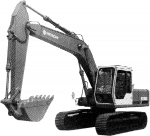
Hitachi Excavator EX150 Hydraulic Excavator Factory Service & Shop Manual


Pages from KM10100 – Hitachi Excavator EX150 Hydraulic Excavator Technical Service Manual


INSTANT DOWNLOAD


Complete workshop & service manual with electrical wiring diagrams for Hitachi Excavator EX150 Hydraulic Excavator. It’s the same service manual used by dealers that guaranteed to be fully functional and intact without any missing page.

This Hitachi Excavator EX150 Hydraulic Excavator service & repair manual (including maintenance, overhaul, disassembling & assembling, adjustment, tune-up, operation, inspecting, diagnostic & troubleshooting…) is divided into different sections. Each section covers a specific component or system with detailed illustrations. A table of contents is placed at the beginning of each section. Pages are easily found by category, and each page is expandable for great detail. The printer-ready PDF documents work like a charm on all kinds of devices.

EM13314 – Hitachi Excavator EX150 Operator’s Manual.pdf
KM10100 – Hitachi Excavator EX150 Hydraulic Excavator Technical Service Manual.pdf

EXCERPT:
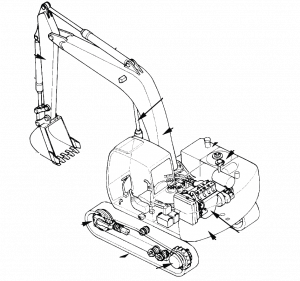
UNDERCARRIAGE
2. SWING BEARING
2.1 CONSTRUCTION & FUNCTION
The swing bearing supports the superstructure and makes rotation smooth.
This swing bearing is a single row shear type ball bearing.
The major parts of the swing bearing are the outer race, the inner race with internal gear, balls, supports and dust seals.
The outer race is bolted to the superstructure.
The inner race is bolted to the undercarriage.
The internal gear is incorporated in the inner ring and meshes with the pinion from the swing reduction device.


INSTANT DOWNLOAD


Posted on

Hitachi Excavator EX80-5 Factory Service & Shop Manual


Pages from 4 Front Attachment

MHITEX80OPES.zip
Price: $29.99 USD

Complete workshop & service manual with electrical wiring diagrams for Hitachi Excavator EX80-5. It’s the same service manual used by dealers that guaranteed to be fully functional and intact without any missing page.

This Hitachi Excavator EX80-5 service & repair manual (including maintenance, overhaul, disassembling & assembling, adjustment, tune-up, operation, inspecting, diagnostic & troubleshooting…) is divided into different sections. Each section covers a specific component or system with detailed illustrations. A table of contents is placed at the beginning of each section. Pages are easily found by category, and each page is expandable for great detail. The printer-ready PDF documents work like a charm on all kinds of devices.

FILELIST:
EM1C1NA21 – Hitachi Excavator EX80-5 Operator’s Manual.pdf
TO152ENA – Hitachi Excavator EX80-5 Technical Manual (Operational Principle).pdf
TT152ENA – Hitachi Excavator EX80-5 Technical Manual (Troubleshooting).pdf
TT152ENACIR – Hitachi Excavator EX80-5 Circuit Diagrams.pdf
W152ENA – Hitachi Excavator EX80-5 Workshop Manual.pdf
T152ENA00CIR (attach to TT152E-NA) – Hitachi Excavator EX80-5 Electrical Diagram & Harness
W152ENA00 – Hitachi Excavator EX80-5 Workshop Manual
1 General Information.pdf
2 Upperstructure.pdf
3 Undercarriage.pdf
4 Front Attachment.pdf
5 Engine and Accessory.pdf
Index.pdf

EXCERPT:
SECTION 4
FRONT ATTACHMENT
—CONTENTS—
Group 1 Front Attachment
Remove and Install
Front Attachment ……..W4-1-1
Maintenance Standard……W4-1-8
Standard Dimensions for Arm and Bucket
Connection …….W4-1-11
Group 2 Cylinder
Remove and Install Cylinder …..W4-2-1
Disassemble Cylinder …..W4-2-11
Assemble Cylinder ……W4-2-26
Maintenance Standard……..W4-2-32

Remove Bucket Cylinder
CAUTION: Prevent personal injury. Metal
debris may fly off when a hammer is used to remove pins.
1. Lay wooden blocks under the arm tip and in the clearance between arm (2) top surface and bucket cylinder (1).
IMPORTANT: Before removing pin (6), secure links with wires to prevent links from falling.
2. Remove ring (5) and stopper pin (3) from the link to remove pin (6). Remove thrust plates (4) from the mating faces between the links and the bucket
cylinder rod.
3. Bind cylinder rod (7) with wire so that cylinder rod (7) is not extended.

Posted on

John Deere 204K and 304K Loader Repair Manual


Pages from TM12988 – 204K and 304K Loader Repair Manual

MJOD204K304KOPES.zip
Price: $29.99 USD

Complete workshop & service manual with electrical wiring diagrams for John Deere 204K and 304K Loader. It’s the same service manual used by dealers that guaranteed to be fully functional and intact without any missing page.

This repair manual (including maintenance, overhaul, disassembling & assembling, adjustment, tune-up, operation, inspecting, diagnostic & troubleshooting…) is divided into different sections. Each section covers a specific component or system with detailed illustrations. A table of contents is placed at the beginning of each section. Pages are easily found by category, and each page is expandable for great detail. The printer-ready PDF documents work like a charm on all kinds of devices.

TM12988 – John Deere 204K and 304K Loader Repair Manual.pdf

Table of Contents
Foreword 5
Manual Identification—READ THIS FIRST! 6
00 – General Information 9
00 – General Information 01 – Safety 9
Add and Operate Attachments Safely 9
Add Cab Guarding for Special Uses 10
Avoid Backover Accidents 11
Avoid High-Pressure Fluids 12
Avoid High-Pressure Oils 13
Avoid Machine Tip Over 14
Avoid Unauthorized Machine Modifications 15
Avoid Worksite Hazards 16
Clean Debris from Machine 17
Dispose of Waste Properly 18
Drive Metal Pins Safely 19
Follow Safety Instructions 20
Inspect and Maintain ROPS 21
Inspect Machine 22
Keep Riders Off Machine 23
Make Welding Repairs Safely 24
Operate Only If Qualified 25
Operating on Slopes 26
Operating or Traveling On Public Roads 27
Park and Prepare for Service Safely 28
Prepare for Emergencies 29
Prevent Battery Explosions 30
Prevent Fires 32
Prevent Unintended Machine Movement 33
Recognize Safety Information 34
Remove Paint Before Welding or Heating 35
Service Cooling System Safely 36
Service Tires Safely 37
Start Only From Operator’s Seat 39
Stay Clear of Moving Parts 40
Use and Maintain Seat Belt 41
Use Special Care When Operating Loader 42
Use Steps and Handholds Correctly 43
Wear Protective Equipment 44
Work In Ventilated Area 45
00 – General Information 03 – Torque Values 46
Additional Metric Cap Screw Torque Values 46
Inch Series Four Bolt Flange Fitting For High Pressure Service Recommendations 48
Metric 24° O-Ring Seal DIN 20078 Service Recommendations 50
Metric Bolt and Cap Screw Torque Values 52
Service Recommendations For Inch Series Four Bolt Flange Fittings 53
Service Recommendations for Metric Series Four Bolt Flange Fitting 54
Service Recommendations For Non-Restricted Banjo (Adjustable) Fittings 55
Service Recommendations For O-Ring Boss Fittings With Shoulder 57
Unified Inch Bolt and Cap Screw Torque Values 60
01 – Wheels 61
Tire Remove and Install 61
Wheel Remove and Install 64
02 – Axles and Suspension Systems 65
Drive Shaft Remove and Install 65
Front and Rear Axle Disassemble and Assemble 67
Front Axle Remove and Install 68
Rear Axle Reduction Gear Case Disassemble and Assemble 71
Rear Axle Reduction Gear Case Remove and Install 72
Rear Axle Remove and Install 73
03 – Transmission 77
Charge Pump Remove and Install 77
Creep Control Valve Remove and Install 78
Directional Control Valve Remove and Install 80
Hydrostatic Motor Disassemble and Assemble 81
Hydrostatic Motor Remove and Install 82
Hydrostatic Pump Disassemble and Assemble 85
Hydrostatic Pump Remove and Install 86
Hydrostatic Pump Valves Remove and Install 90
Hydrostatic Start-Up Procedure 91
04 – Engine 93
Engine Remove and Install 93
John Deere Engine 100
Starter Motor Remove and Install 101
05 – Engine Auxiliary Systems 102
Air Intake System Remove and Install 102
Cooling Package Remove and Install 104
Fan Remove and Install 108
Fuel Tank Remove and Install 110
Muffler Remove and Install 113
07 – Dampener Drive 115
Damper Plate Remove and Install 115
09 – Steering System 117
Cab Steering Column Remove and Install 117
Canopy Steering Column Remove and Install 118
Orbital Steering Valve Assemble 120
Orbital Steering Valve Disassemble and Inspect 124
Orbital Steering Valve Remove and Install 129
Steering Cylinder Disassemble and Assemble 131
Steering Cylinder Remove and Install 133
10 – Service Brakes 135
Brake _ Inching Valve Assembly Remove and Install 135
Drum Brake Bleed 138
Drum Brake Remove and Install 140
Service Brakes (Wet Disc) Remove and Install 142
11 – Park Brake 143
Park Brake Valve Remove and Install 143
17 – Frames, Chassis, or Supporting Structure 145
Counterweight Remove and Install 145
Loader and Rear Frames Separation 147
Lower Pivot Bushing Assembly Remove and Install 150
Rear Link and Bushing Assembly Remove and Install 151
Upper Pivot Bushing Assembly Remove and Install 152
Welding Repair of Major Structures 153
18 – Operator’s Station 154
Air Conditioner Compressor Remove and Install 154
Air Conditioner Freeze Control Switch Remove and Install 156
Air Conditioner High _ Low Pressure Switch Remove and Install 157
Air Conditioner _ Heater Module Remove and Install 158
Blower Motor Remove and Install 162
Cab Remove and Install 164
Canopy Remove and Install 171
Charge R134a System 177
Condenser Remove and Install 179
Evacuate R134a System 181
Evaporator Coil Remove and Install 183
Expansion Valve Remove and Install 186
Flush and Purge Air Conditioner System 188
Heater Control Valve Remove and Install 192
Heater Core Remove and Install 194
R134a Refrigerant Oil Information 196
R134a Refrigerant Recovery _ Recycling and Charging Station Installation Procedure 198
Rear Wiper Motor Remove and Install 199
Receiver-Dryer Remove and Install 202
Recover R134a Refrigerant 203
Refrigerant Cautions and Proper Handling 204
Seat Remove and Install 205
Windowpanes Remove and Install 207
Windshield Wiper Motor Remove and Install 208
19 – Sheet Metal and Styling 211
Hood Remove and Install 211
Rear Fenders Remove and Install 213
21 – Main Hydraulic System 215
General Hydraulic Oil Cleanup Procedure 215
Hydraulic Component Failure Cleanup Procedure 218
Hydraulic Oil Reservoir Remove and Install 221
Hydraulic Pump _ Priority Valve Disassemble and Assemble 224
Hydraulic Pump _ Priority Valve Remove and Install 225
Hydraulic Start-Up Procedure 227
31 – Loader 229
Bolt-On Cutting Edge Remove and Install 229
Boom and Bucket Cylinders Disassemble and Assemble 230
Boom and Bucket Linkage Remove and Install 232
Boom Cylinder Remove and Install 234
Bucket Cylinder Remove and Install 237
Bucket Linkage Bushings Remove and Install 240
Cracked Cutting Edge Repair 241
Loader Boom Bushings Remove and Install 242
Loader Control Valve Remove and Install 243
Quik-Tatch™ Actuator Remove and Install 247
Quik-Tatch™ Coupler Remove and Install 248
Welded-On Bucket Cutting Edge Remove and Install 251

EXCERPT:
LV10548 – Cap Screw Tightening Sequence 6
PC10857XW – Avoid Backover Accidents 7
T113889 – Connection 8
T113948 – Non-Restricted Banjo Fitting 9
T113957 – O-Ring Boss Fitting With Shoulder 10
T133038 – Weld-On Cutting Edge 11
T133039 – Bolt-On Cutting Edge 12
T133468 – Use Handholds And Steps 13
T141670 – Worksite Hazards 14
T141671 – Keep Riders Off Machine 15
T141672 – Ensure solid footing 16
T141672 – Worksite Hazards 17
T141676 – Do Not Jump 18
T141681 – Operating on Slopes 19
T141891 – Operating or Traveling On Public Roads 20
T141894 – Avoid contact with gas lines 22
T141902 – Use Secial Care When Operating Loader 23
T141957 – Never Use Loader to Lift People 24
T142001 – Park Brake Switch 25
T200177 – Bucket Tilt Linkage Seals and Bushings 26
T204187 – Drum Brake Component Location 27
T204413 – R134a Recovery and Charging Station Installation 28
T216429 – Supporting Loader 29
T217481 – Orientation of Centering Spring Set 30
T217488 – Steering Valve Timing Marks 31
T6873AA – T-Bolt 32
T6873AB – H-Bolt 33
T6873AC – M-Bolt 34
T6890BB – Flange Fittings 35
T6890BB – Four Bolt Flange Fittings 36
T6890BB – Metric Series Four Bolt Flange Fitting 37
TS952 – Explosive Single Piece Rim and Tire 38
TX1055625 – Hydraulic Pump Exploded View 39
TX1136696 – Example of PIN Plate 40
TX1136697 – PIN Plate Location 41
TX1138418 – Hydrostatic Pump 42
TX1145042A – Wheel 43
TX1145134A – Front Axle and Frame 44
TX1145135A – Drive Shaft and Brake Line 45
TX1145182A – Front Attachment 46
TX1145193A – Electrical Connector 47
TX1145194A – Quick-Tatch™ Pin (right pin shown) 48
TX1145210 – Steering Cylinder 49
TX1145340 – Drive Shaft 50
TX1145499 – Loader Boom Bushings 51
TX1145528 – Bucket Linkage 52
TX1145531A – Vent Diffusers 53
TX1145532A – Side Access Panel 54
TX1145533A – Fuse and Relay Board Assembly 55
TX1145566A – Air Conditioner 56
TX1145567A – Expansion Valve 57
TX1145643A – Heater Control Valve 58
TX1145658A – Expansion Valve 59
TX1145681A – Air Conditioner 60
TX1145682A – Air Conditioner 63
TX1145684A – Heater Core and Blower Motor Assembly 66
TX1145686A – Heater Core 68
TX1145702A – Evaporator Coil 69
TX1145703A – Expansion Valve 70
TX1145704A – Air Conditioning Freeze Control Switch Probe 71
TX1145766A – Air Conditioning Freeze Control Switch 72
TX1145792A – Pin (upper shown) 73
TX1145793A – Pin (lower shown) 74
TX1145795A – Covers 75
TX1146015A – Rear Light Electrical Connectors 80
TX1146041A – Windshield Wiper Arms 81
TX1146042A – Interior Vent Assembly 82
TX1146043A – Wiper Motor 83
TX1146102A – Jack Stand Position 84
TX1146127A – Pin (rear of cylinder) 85
TX1146128A – Hydraulic Hose and Pin (front of cylinder) 86
TX1146130A – Hydraulic Hose 87
TX1146258A – Receiver-Dryer 88
TX1146261A – Air Conditioner High 89
TX1146286A – Hydraulic Hose (front shown) 90
TX1146288A – Pin (front shown) 91
TX1146289A – Hydraulic Hose (rear shown) 92
TX1146435A – Switch Panel 93
TX1146436A – Panel 94
TX1146437A – Pilot Lever 95
TX1146440A – Backside of Receiver-Dryer 96
TX1146492A – Cover 97
TX1146507A – Counterweight Access Panel 98
TX1146508A – Charge Pump 100
TX1146529A – Control Valve 101
TX1146548A – Auxiliary Lever 102
TX1146568A – Hydrostatic Pump and Electrical Connectors 103
TX1146569A – Hydrostatic Pump Removal 104
TX1146641A – Quik-Tatch™ Actuator 105
TX1146803A – Air Conditioner Compressor 106
TX1146804A – Air Conditioner Compressor (end view) 107
TX1146810A – Flywheel Housing 108
TX1146811A – Damper Plate 109
TX1146817A – Lower Bushing 110
TX1146823 – Upper Bushing 111
TX1146855A – Hydraulic Return Filter Hoses 112
TX1146856A – Fuel Lines and Fuel Level Sensor 113
TX1146857A – Engine Panels and Hydraulic Oil Temperature Switch 114
TX1146858A – Fuel Tank Removal 115
TX1146859A – Hydraulic Return Filter Hoses 116
TX1146860A – Hydraulic Oil Reservoir (front shown) 117
TX1146861A – Hydraulic Oil Reservoir Removal 118
TX1146922 – Link, Bushing, and Pin 119
TX1146930A – Rear Interior Cover 120
TX1146932A – Speaker (left speaker shown) 121
TX1146933A – Switch Panel 122
TX1146935A – Underside of Switch Panel 123
TX1146936A – Rear Wiper Arm 124
TX1146937A – Rear Wiper Motor 125
TX1147019A – Coolant Hoses 126
TX1147036A – Refrigerant Hoses 127
TX1147038A – Covers 128
TX1147039A – Windshield Wiper Arms 129
TX1147150A – Fuse Box 130
TX1147153A – Ground 131
TX1147155A – Fuse Box (rear shown) 132
TX1147157A – Foot Pedal (bottom shown) 133
TX1147158A – Foot Pedal (top shown) 134
TX1147163A – Rear Washer Hose 135
TX1147164A – Connector 136
TX1147166A – Block Heater Plug 137
TX1147167A – Cable 138
TX1147252A – Intake Tube 139
TX1147283A – Hood Removal 141
TX1147292A – Cooling Package Hoses 142
TX1147293A – Receiver-Dryer Retainer Nuts 143
TX1147296A – Condenser 144
TX1147299A – Counterweight 145
TX1147331A – Cooling Package 146
TX1147336A – Condenser 147
TX1147337A – Counterweight Access Panel 148
TX1147368 – Boom Cylinder 149
TX1147369 – Steering Cylinder 150
TX1147371 – Bucket Cylinder 151
TX1147439A – Rear Axle 152
TX1147523A – Park Brake Valve 153
TX1147527A – Creep Control Valve 154
TX1147562A – Hydrostatic Motor Drain Plug 155
TX1147564A – Hydrostatic Motor 156
TX1147565A – Cab Mount 157
TX1147587 – Seat 158
TX1147596A – Brake Pedal 159
TX1147597A – Brake-Inching Valve Assembly 160
TX1147598A – Brake-Inching Valve (end view) 161
TX1147599A – Brake-Inching Valve Cap Screws 162
TX1147614A – Right Rear Fender 163
TX1147615A – Left Rear Fender and Step 164
TX1147616A – Air Intake System 165
TX1147687A – Steering Valve 166
TX1147737A – Hydraulic Hoses 167
TX1147747A – Access Cover 168
TX1147748A – Steering Column Mount 169
TX1147754A – Electrical Connectors 170
TX1147786A – Muffler 171
TX1147787A – Muffler Mount 172
TX1147788A – Exhaust Manifold Nuts 173
TX1147793A – Fan 174
TX1147873A – Exhaust Pipe 175
TX1148044A – Fuse Box 176
TX1148045A – Ground 177
TX1148046A – Fuse Box (rear shown) 178
TX1148047A – Foot Pedal (bottom shown) 179
TX1148049A – Foot Pedal (top shown) 180
TX1148050A – Connector 181
TX1148051A – Canopy Mount 182
TX1148073A – Electrical Connector 183
TX1148074A – Electrical Connector 184
TX1148075A – Electrical Connector 185
TX1148076A – Control Valve 186
TX1148077A – Control Valve (rear cap screws shown) 187
TX1148241A – Hydraulic Oil Filter Cap 188
TX1148242A – Hydraulic Reservoir and Wands 189
TX1148256A – Steering Column 190
TX1148259A – Steering Column Mount 191
TX1148685A – Cover 192
TX1148890A – Orbital Valve 193
TX1148897A – Cover 194

TM12988 – 204K and 304K Loader
Expansion Valve Remove and Install
1. Park and prepare machine for service safely. See Park and Prepare for Service Safely . (Group 0001.)
2. Recover refrigerant from system. See Recover R134a Refrigerant . (Group 1830.)
3. Turn battery disconnect switch to the OFF position. See Battery Disconnect Switch . (Operator’s Manual.)
4. TX1145795A-UN: Covers
LEGEND:
1 – Screw (4 used)
2 – Center Access Cover
3 – Screw (8 used)
4 – Cab Front Cover
Remove center access cover (2).
5. Remove cab front cover (4).
6. TX1145658A-UN: Expansion Valve
LEGEND:
5 – High-Pressure Refrigerant Hose
6 – High-Pressure Refrigerant Line
7 – Low-Pressure Refrigerant Line
8 – Expansion Valve
9 – Screw (2 used)
10 – Low-Pressure Refrigerant Hose
11 – Screw
Install identification tags, loosen screw (11), and disconnect refrigerant hoses (5 and 10) from expansion valve (8). Close all openings using caps and plugs.
7. Loosen screws (9) and remove expansion valve from refrigerant lines (6 and 7). Close all openings using caps and plugs.

Posted on

JCB Rough Terrain Fork Lift 926/930/940 Factory Service & Shop Manual


Pages from 9803-5100 – JCB Rough Terrain Fork Lift (926, 930, 940) Service Manual

MJCBRTFLOPEK.zip
Price: $29.99 USD

Complete workshop & service manual with electrical wiring diagrams for JCB Rough Terrain Fork Lift (926, 930, 940). It’s the same service manual used by dealers that guaranteed to be fully functional and intact without any missing page.

This JCB Rough Terrain Fork Lift (926, 930, 940) service & repair manual (including maintenance, overhaul, disassembling & assembling, adjustment, tune-up, operation, inspecting, diagnostic & troubleshooting…) is divided into different sections. Each section covers a specific component or system with detailed illustrations. A table of contents is placed at the beginning of each section. Pages are easily found by category, and each page is expandable for great detail. The printer-ready PDF documents work like a charm on all kinds of devices.

9803-5100 – JCB Rough Terrain Fork Lift (926, 930, 940) Service Manual.pdf

EXCERPT:
Service Manual
Rough Terrain Fork Lift
Section 1 – General Information
Section 2 – Care and Safety
Section 3 – Maintenance
Section A – Attachments
Section B – Body and Framework
Section C – Electrics
Section E – Hydraulics
Section F – Transmission
Section G – Brakes
Section H – Steering
Section K – Engine

Removal and Replacement
Removal
1 Before commencing, set machine in straight ahead position on firm level ground. Apply parking brake and stop engine.
2 Remove carriage and forks. K Removal ( T B-15).
3 Disconnect and plug hydraulic hoses 39-A and breather pipe 39-B. View 39-X shows the arrangement for early models whilst view 39-Y shows later models; refer to the view applicable to your machine.
4 Attach a hoist to the top of the mast to prevent mast tipping when tilt rams are disconnected.
5 Support tilt rams. Remove bolts 39-C, washers 39-D and pivot pins 39-E and withdraw tilt rams.
6 Take weight of mast on the hoist. Remove bolts 39-F, pivot pins 39-G and lower mast to ground.
Replacement
The procedure for replacing the mast is a reversal of the removal procedure.

Posted on

JCB Manual Pack


Pages from 9803-1400 – JCB Attachments Service Manual

MJCBMISCOPMK.zip
Price: $29.99 USD

JCB Manual Pack

FILELIST:
9801-9907 – JCB VLT Lighting Tower Operator Manual.pdf
9803-1400 – JCB Attachments Service Manual.pdf
9803-9320 – JCB Dumpster TD7, TD10 Service Manual.pdf
9803-9430 – JCB ZT 20D Service Manual.pdf
9803-9570 – JCB Dumpster HTD5 Service Manual.pdf
9803-9985 – JCB CP1 & CP2 Digital Control Panels Service Manual.pdf
9806-2150 – JCB Industrial Engine Systems LPG 3.0 Engine Workshop Manual.pdf
9806-3080 – Lombardini indirect injection Diesel engines type 15LD225, 15LD315, 15LD350, 15LD400, 15LD440 Workshop Manual.pdf
9806-4005a – Lombardini Gearbox Workshop Manual.pdf
9806-4060 – Lombardini CHD series Engine Workshop Manual.pdf
9806-4061 – Lombardini LDW 1503, LDW 1603, LDW 2004, LDW 2004/T, LDW 2204, LDW 2204/T CHD Use & Maintenance Manual.pdf
9806-4650 – Installation, Service & Maintenance Manual for STAMFORD BC Range of Generators.pdf
9806-4750 – Himoinsa Generators Self-regulating Alternators Series Eco-ECP Operating & Maintenance Instructions.pdf
9806-4800 – JCB Digital Control Panel Operators Manual.pdf
9806-5000 – Sincro SK160 4 Poles Brushless Alternators Use and Maintenance Manual.pdf
9811-1870 – Generator Set – G50R, G80R, G55X, G55QX, G66X, G66QX, G88X, G88QX, G110X, G110QX, G120X, G120QX Operator Manual.pdf
9811-2800 – Generator Set – G17, G17Q, G20R, G22, G22Q, G30R, G33, G33Q Operator Manual.pdf
9811-2850 – Generator Set – G144, G144Q, G175, G175Q, G220, G220Q, G130R, G160R, G200R Operator Manual.pdf
9811-2900 – Generator Set – G330, G330Q, G350, G350Q, G380, G380Q, G400, G400Q, G400, G440Q, G550, G550Q Operator Manual.pdf
9811-4550 – Generator Set – Models G8X to G45QX Operator Manual.pdf
9811-4600 – Generator Set – Models G60RX to G115QX Operator Manual.pdf
9811-4650 – Generator Set – Models G130RX to G220QX Operator Manual.pdf
9811-4700 – Generator Set – Models G250RX to G600X Operator Manual.pdf
9811-5050 – Lighting Tower LT9 Operator Manual.pdf
9821-1950 – Lighting Tower LTM9 Operator Manual.pdf

EXCERPT:
Service Manual Dumpster TD7, TD10
General Information 1
Care & Safety 2
Routine Maintenance 3
Attachments A
Body & Framework B
Electrics C
Controls D
Hydraulics E
Gearboxes F
Track & Running Gear J
Engine L

Hydraulic Fluid Quality
Construction machinery uses a large volume of fluid in the hydraulic system for power transmission, equipment lubrication, rust prevention and sealing.
According to a survey conducted by a pump manufacturer, seventy per cent of the causes of problems in hydraulic equipment were attributable to inadequate maintenance of the quality of the hydraulic fluid.
Therefore, it is obvious that control of the quality of the hydraulic fluid helps prevent hydraulic equipment problems and greatly improves safety and reliability. Furthermore from an economic angle it extends the life of the hydraulic fluid if quality is maintained.
Effects of Contamination
Once inside the system, hydraulic circuit contaminants greatly effect the performance and life of hydraulic equipment. For example, contaminants in a hydraulic pump develop internal wear to cause internal leakage and hence lower discharges. Wear particles generated will circulate with the hydraulic fluid to cause further deterioration in the performance of this and other equipment.
Contaminants also enter principal sliding sections of the equipment causing temporary malfunction, scuffing, sticking and leakage and can lead to major problems.
The main contaminants can be classified as follows:-
1 Solid Particles – sand, fibres, metallic particles, welding scale, sealing materials and wear particles etc.