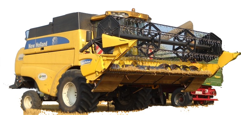
New Holland CL560, CS520, CS540, CS640, CS660
Complete workshop & service manual with electrical wiring diagrams for New Holland CL560, CS520, CS540, CS640, CS660 Combines. It’s the same service manual used by dealers that guaranteed to be fully functional and intact without any missing page.
This service & repair manual (including maintenance, overhaul, disassembling & assembling, adjustment, tune-up, operation, inspecting, diagnostic & troubleshooting…) is divided into different sections. Each section covers a specific component or system with detailed illustrations. A table of contents is placed at the beginning of each section. Pages are easily found by category, and each page is expandable for great detail. The printer-ready PDF documents work like a charm on all kinds of devices.
“6043401100.pdf”
New Holland CL560, CS520, CS540, CS640, CS660 Combines Repair Manual
604_34_011_00 5 27/05/2005
2,446 pages
Contents
INTRODUCTION
DISTRIBUTION SYSTEMS A
POWER PRODUCTION B
POWER TRAIN C
TRAVELLING D
BODY AND STRUCTURE E
FRAME POSITIONING F
TOOL POSITIONING G
CROP PROCESSING K
…
EXCERPT:
BODY AND STRUCTURE – ENVIRONMENT CONTROL Heating system
ENVIRONMENT CONTROL Heating system – Check (E.40.B – F.45.A.10)
CS540, CS640, CS520, CS660, CL560
1. Check that both engine coolant shutoff valves at the engine block are open.
(CCW = Open, CW = Closed)
2. Check that the heater supply hose at the rear of the engine head is warm.
3. Check that the engine coolant temperature is at least 76 ° C (170 ° F).
4. Check the cab fresh air filter to check that it is clean and free from obstruction to air flow.
5. Check the cab recirculation air filter to see that it is clean and free from obstruction to air flow.
BODY AND STRUCTURE – E
ENVIRONMENT CONTROL Heating system – 40.B
ENVIRONMENT CONTROL Heating system – Check (E.40.B – F.45.A.10)
CS540, CS640, CS520, CS660, CL560
…