Pages from 9813-1250 – JCB JS240, JS260, JS330, JS360 – Tier 4 Hydraulic Excavator Service Manual
Complete workshop & service manual with electrical wiring diagrams for JCB JS200LC, JS240, JS240LC, JS260, JS330, JS300LC, JS360, JS450, JS450LC, JS460 Hydraulic Excavators. It’s the same service manual used by dealers that guaranteed to be fully functional and intact without any missing page.
This JCB JS200LC, JS240, JS240LC, JS260, JS330, JS300LC, JS360, JS450, JS450LC, JS460 Hydraulic Excavators service & repair manual (including maintenance, overhaul, disassembling & assembling, adjustment, tune-up, operation, inspecting, diagnostic & troubleshooting…) is divided into different sections. Each section covers a specific component or system with detailed illustrations. A table of contents is placed at the beginning of each section. Pages are easily found by category, and each page is expandable for great detail. The printer-ready PDF documents work like a charm on all kinds of devices.
FILELIST:
9803-6200 – JCB JS200LC, JS240LC, JS300LC, JS450LC Hydraulic Excavator Service Manual.pdf
9803-6420 – JCB JS330, JS450, JS460 Hydraulic Excavator Service Manual.pdf
9806-2240 – JCB AA-6SD1T Engine (JS460 applicable) Service Manual.pdf
9813-1250 – JCB JS240, JS260, JS330, JS360 – Tier 4 Hydraulic Excavator Service Manual.pdf
EXCERPT:
Service Manual
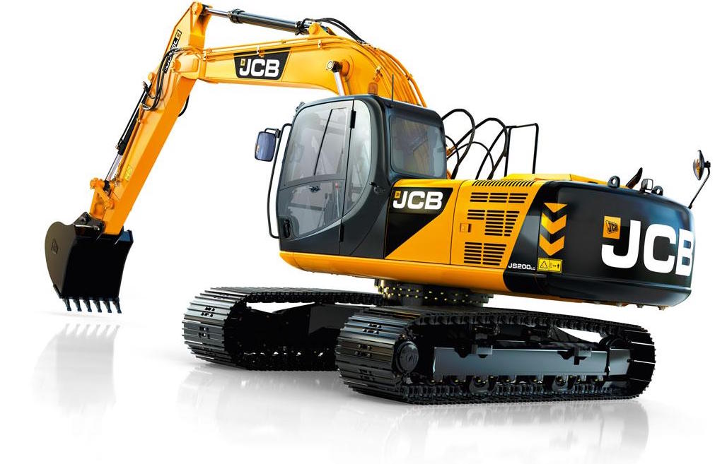
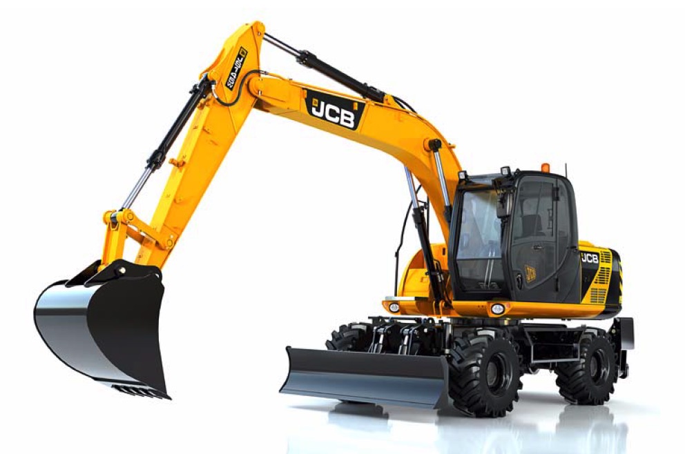
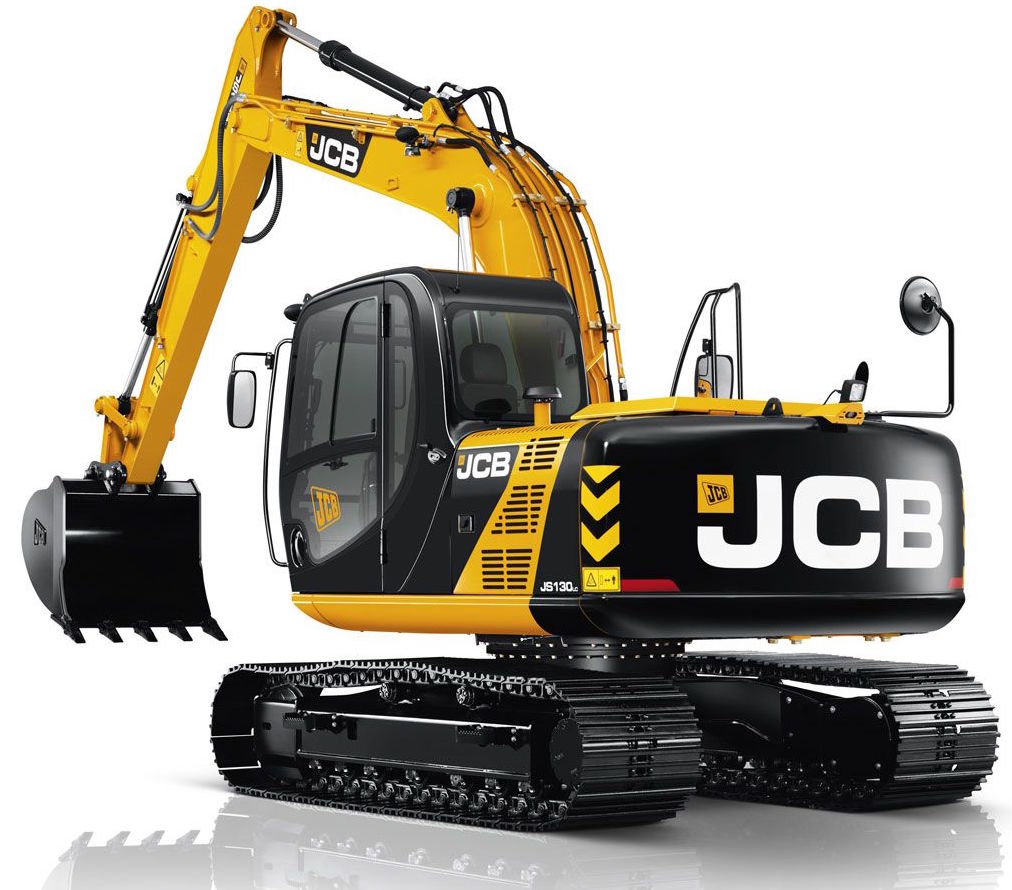
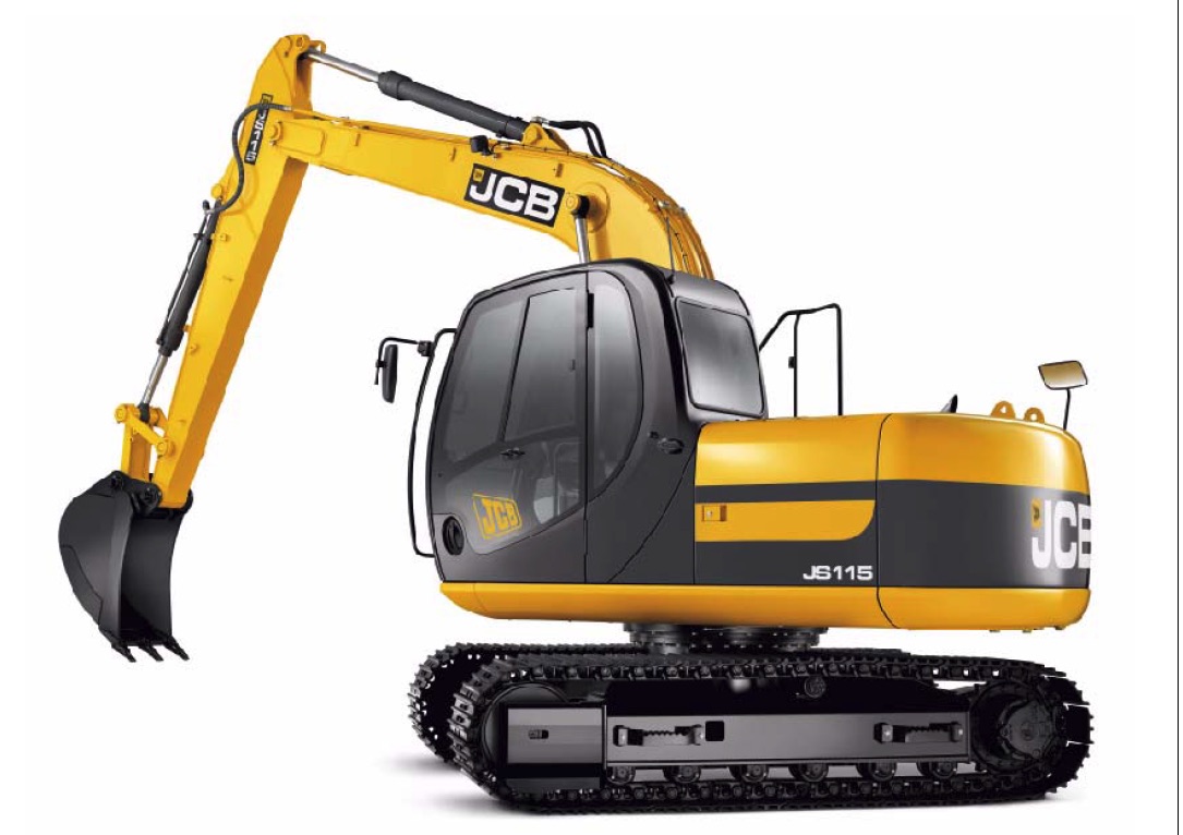
JS240, JS260, JS330, JS360 – Tier 4
Section 1 – General Information
Section 2 – Care and Safety
Section 3 – Maintenance
Section B – Body & Framework
Section C – Electrics
Section E – Hydraulics
Section F – Transmission
Section J – Track and Running Gear
Section K – Engine
…
JS460 ENGINE SERVICE MANUAL AA-6SDIT
TABLE OF CONTENTS
Chapter 1 General Information . . . . . 1
Chapter 2 Maintenance. . . . . . . 21
Chapter 3 Engine I (Disassembly) . . 37
Chapter 4 Engine II (Inspection and Repair) . . . . 55
Chapter 5 Engine III (Assembly) . . . . 85
Chapter 6 Lubricating System. . . . . . 117
Chapter 7 Cooling system. . . . 129
Chapter 8 Fuel System. . . . . . . . 139
Chapter 9 Turbocharger . . . . . . 153
Chapter 10 Engine Electrical . . 173
Chapter 11 Troubleshooting. . . 197
Chapter 12 Special Tools. . . . . . . 219
Chapter 13 Repair Standard. . . 223
Note:
Before using this manual to perform maintenance and repairs, be sure to read the section “General Servicing Precautions” included in Chapter 1 (General Information).
…
Assembly
1 Position main housing 301 on a bench with the flange for valve housing 303 uppermost.
2 Take output shaft 101 and fit stop ring 432 and spacer 106 at the splined output end. Shrink fit bearing 443 to the output shaft with annulus A against the spacer.
3 If renewing bearing 444, shrink fit inner race to the output shaft, followed by stop ring 433.
4 Install the output shaft assembly into main housing 301. Tap the outer casing of bearing race 443 using a copper bar until it is fully seated.
Fig 34.
Fig 35.
5 Using a suitable jig, install a new oil seal 491 into front cover 304. Make sure the oil seal is installed the right way round (see Dismantling, step 17).
6 Apply a little grease to the lip of oil seal 491 and new O-ring 471. Cover the spline of output shaft 101 with tape and then install front cover 304 carefully by tapping gently with a plastic hammer at different positions all round the outside edge.
7 Secure front cover 304 with snap ring 437.
8 Position main housing 301 horizontally on the bench.
Smear shoe plate 124 with grease and then install with its large chamfered side against the housing.
…