Posted on

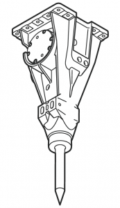
JCB Hammermaster, Rockbreakers, HM Range Medium, Large Hydraulic Breakers Factory Service & Shop Manual


Pages from 9803-1420 – JCB HM Range Medium, Large Hydraulic Breakers Service Manual

MJCBBREAKEROPES.zip
Price: $29.99 USD

Complete workshop & service manual with electrical wiring diagrams for JCB Hammermaster, Rockbreakers, HM Range Medium, Large Hydraulic Breakers. It’s the same service manual used by dealers that guaranteed to be fully functional and intact without any missing page.

This JCB Hammermaster, Rockbreakers, HM Range Medium, Large Hydraulic Breakers service & repair manual (including maintenance, overhaul, disassembling & assembling, adjustment, tune-up, operation, inspecting, diagnostic & troubleshooting…) is divided into different sections. Each section covers a specific component or system with detailed illustrations. A table of contents is placed at the beginning of each section. Pages are easily found by category, and each page is expandable for great detail. The printer-ready PDF documents work like a charm on all kinds of devices.

FILELIST:
9803-1300 – JCB Hammermaster, Rockbreakers Service Manual.pdf
9803-1420 – JCB HM Range Medium, Large Hydraulic Breakers Service Manual.pdf

EXCERPT:
Contents Page No.
Hammermaster Identification 1 – 1
Torque Settings
Hammermaster 360 Range 2 – 1
Hammermaster 460-110 2 – 3
Hammermaster 560 2 – 4
Hammermaster 660 2 – 5
Hammermaster 760 2 – 6
Hammermaster 860 2 – 7
Hammermaster 960 2 – 8
Hammermaster 160 Range 2 – 9
Hammermaster 260 Range 2 – 10
Hammermaster 570 2 – 11
Hammermaster 670 2 – 12
Hammermaster 770 2 – 13
Hammermaster 1050, 1150 2 – 14
Hammermaster 1350, 1450 2 – 15
Hammermaster 1750 2 – 16
Hammermaster 2350/2950/3850/3950 2 – 17
Hammermaster 550 2 – 18
Hammermaster 850 2 – 19
Service Tools 3 – 1
Nord-Lock Washers 3 – 1
Accumulator Charging 3 – 2
Safety Notices 4 – 1
General Safety 5 – 1
Operating Safety 6 – 1
Maintenance Safety 7 – 1
Safety Decals 8 – 1
Lubricants – Health and Safety 9 – 1
Note: Hammermaster 70 – All Service Information relating to this hammer is contained in Section 13. Safety requirements are retained in this section.
Note: Hammermaster 100 and Hammermaster 115 – All Service
Information relating to these hammers is contained in Section 20.
Safety requirements are retained in this section.

Contents Page No.
i i
Medium Breakers
Introduction …………1
Safety ….1
General Information …..1
Workshop Standards …………..1
Spare Parts …….1
Service Personnel …….1
Using this Manual ……..2
Standard Symbols …………3
Service Tools ………5
Charging Equipment …….10
Medium Breakers – HM165Q, 265Q, 385Q, 495Q
Dismantling ………. 11
Assembly ………….18
Field Bushing Exchange …………23
Charging the Accumulator ………25
Hanger Brackets ………….27
Exploded Views …………..28
Operating Principles …….32
Stage 1 – Start Up ……32
Stage 2 – Return Stroke ……..32
Stage 3 – Power Stroke ………33
Stage 4 – End of Power Stroke ……..33
Medium Breakers – HM386Q
Special Tools …….34
Dismantling ……….38
Assembly ………….45
Operating Principles …….54
Stage 1 ………..54
Stage 2 ………..54
Stage 3 ………..55
Stage 4 ………..55
Stage 5 ………..56
Medium Breakers
Technical Specifications …………57
Nitrogen Adaptor Reference Chart …….58
Tool Part Numbers ……….63
Breaker Part Number Matrix ……64

Chapter Title Page
Introduction
1 General 1
1.1 Explanation of the symbols in the repair manual 1
Safety
2 Operational safety 2
2.1 General 2
2.2 Accident prevention regulations 2
2.3 Safety Notices 3
Tools
3 Tools 5
3.1 General tools 5
3.2 Service box 6
3.3 Special accessories 7
3.3.1 Accumulator charging device 7
3.3.2 Power wrench 8
3.3.3 HeliCoil-tools 8
3.3.4 Fitting aid for piston 9
3.3.5 Press-out aid for wear bushes 9
3.4 Consumables 10
Technical Specifications
4 Technical Specifications 11
4.1 Breaker Specifications 11
4.2 Working Pressure/Required Flow/Engine RPM 16
Dismantling
5 Dismantling the Hydraulic Breaker 21
5.1 Fitting/Removing the Tool 21
5.2 Removing the Power Cell from the Hammer Housing 22
5.3 Removing the High-Pressure Accumulator 23
5.4 Removing the Control System 24
5.5 Removing the Control Slide Valve 24
5.6 Removing the Frequency Switching System 25
5.7 Removing the Cylinder Cover 26
5.8 Removing the Piston and sealing Bush 28
5.9 Removing the Cylinder 28
5.10 Removing the Locking Pins for the Retainer Bars in the Lower Breaker Part 29
5.11 Removing the Locking Bushes 29
Checking
6 Checking the Hammer Housing 30
6.1 Checking for Cracks and Indentations 30
6.2 Wear to the Bottom Plate 30
6.3 Checking the Elastic Pad 31
6.4 Checking the Damping Elements 31
6.5 Checking the Guide Plates 32
6.6 Checking the Tool for Wear 33
Assembling
7 Assembling the Hydraulic Hammer 34
7.1 Tightening Torques for Screws and Screw Couplings on the JCB HM 860Q 34
7.2 Tightening Torques for Screws and Screw Couplings on the JCB HM 1260Q 35
7.3 Tightening Torques for Screws and Screw Couplings on the JCB HM 1560Q 36
7.4 Tightening Torques for Screws and Screw Couplings on the JCB HM 1760Q 37
7.5 Tightening Torques for Screws and Screw Couplings on the JCB HM 2460Q 38
7.6 Tightening Torques for Screws and Screw Couplings on the JCB HM 3060Q and JCB HM
4160Q
39
7.7 Fitting the Cylinder 40
7.8 Fitting the Piston and sealing Bush 40
7.9 Fitting the Cylinder Cover 41
7.10 Fitting the Frequency Switching System 43
7.11 Fitting the Control Slide Valve 44
7.12 Fitting the Control System 44
7.13 Fitting the High-Pressure Accumulator 45
7.14 Checking Pressure in piston Accumulator and Refilling if Required 46
7.15 Fitting the Power Cell into the Hammer Housing 48
7.16 Connecting the JCB AUTOGREASE 49
7.17 Fitting the Tool 50
Changing Seals
8 Changing the Seals 51
8.1 Changing the Cylinder Seals 51
8.2 Changing the Seals between Cylinder and Cylinder Cover 53
8.3 Changing the Seals on the Control System 53
8.4 Changing the Seals on the High Pressure Accumulator 54
8.5 Changing the seals on the Sealing Bush 54
Repair Work
9 Repair Work 55
9.1 Changing the Expansion Bolts on the High-Pressure Accumulator 55
9.2 Changing the High-Pressure Accumulator 55
9.3 Changing the Tie Rods 56
9.4 Removing Scores from Control slide Valve and Bore 57
9.5 Removing Scores on Piston and Cylinder Bore 57
9.6 Changing the Wear Bushes 58
9.7 Replacing the Complete Housing 60
9.8 Replacing Guide Plates and Damping Elements in Housing 60
9.9 Repairing Cracked Welds 61
9.10 Replacing the Bottom Plate on the Housing 61
9.11 Reworking the Retainer Pins for the Damping Elements 62
9.12 Weld Seam Preparation 62
9.13 Preheating Temperature 62
9.14 Fillers 62
9.15 Post-treatment of Welds 62
Spares List
10 Spares List 63
10.1 Percussion Unit 63
10.2 Noise Damping 64
10.3 JCB AUTOGREASE 65
Appendices
1 Breaker Operating Principles 67
2 JCB Autogrease Operating Principles 75
Nitrogen Adaptor Reference Chart
11 Nitrogen Adaptor Reference Chart 90
Tool Part Numbers
12 Tool Part Numbers 92
Breaker Part Number Matrix
13 Breaker Part Number Matrix 93

Posted on

JCB Groundhog/Ground Care/Workmax Factory Service & Shop Manual


Pages from 9813-0450- JCB Workmax 800D Service Manual

MJCBGRUNDOPES.zip
Price: $29.99 USD

Complete workshop & service manual with electrical wiring diagrams for JCB Groundhog 6×4, Groundhog 4×4, Ground Care FM25, Ground Care FM30, Workmax 800D. It’s the same service manual used by dealers that guaranteed to be fully functional and intact without any missing page.

This JCB Groundhog 6×4, Groundhog 4×4, Ground Care FM25, Ground Care FM30, Workmax 800D service & repair manual (including maintenance, overhaul, disassembling & assembling, adjustment, tune-up, operation, inspecting, diagnostic & troubleshooting…) is divided into different sections. Each section covers a specific component or system with detailed illustrations. A table of contents is placed at the beginning of each section. Pages are easily found by category, and each page is expandable for great detail. The printer-ready PDF documents work like a charm on all kinds of devices.

FILELIST:
9803-9390 – JCB Groundhog 6×4 Service Manual.pdf
9803-9820 – JCB Groundhog 4×4 Service Manual.pdf
9803-9830 – JCB Ground Care FM30 Service Manual.pdf
9803-9840 – JCB Ground Care FM25 Service Manual.pdf
9813-0450- JCB Workmax 800D Service Manual.pdf

EXCERPT:
Service Manual
Groundhog 6×4
Section 1 – General Information
Section 2 – Care and Safety
Section 3 – Routine Maintenance
Section A – Optional Equipment
Section B – Body and Framework
Section C – Electrics
Section D – Controls
Section E – Hydraulics
Section F – Transmission
Section G – Brakes
Section H – Steering
Section K – Engine
Section S – Suspension

Service Manual
Workmax 800D
Section 1 – General Information
Section 2 – Care and Safety
Section 3 – Maintenance
Section B – Body and Framework
Section C – Electrics
Section D – Controls
Section F – Transmission
Section G – Brakes
Section H – Steering
Section K – Engine
Section S – Suspension

Adjustment
Rear Axle Sensor
1 Align the gear tooth C with the speed sensor B by turning the rear axle.
2 Remove the sensor from the casing.
3 Screw the sensor B into the casing by hand clockwise until resistance is felt.
4 Unscrew the sensor counter clockwise by 1 to 2 turns.
5 Tighten the securing nut A.

Posted on

JCB Generators Factory Service & Shop Manual


Pages from 9811-4700-1

MJCBGENOPMK.zip
Price: $29.99 USD

Complete workshop & service manual with electrical wiring diagrams for JCB Generators. It’s the same service manual used by dealers that guaranteed to be fully functional and intact without any missing page.

This JCB Generators service & repair manual (including maintenance, overhaul, disassembling & assembling, adjustment, tune-up, operation, inspecting, diagnostic & troubleshooting…) is divided into different sections. Each section covers a specific component or system with detailed illustrations. A table of contents is placed at the beginning of each section. Pages are easily found by category, and each page is expandable for great detail. The printer-ready PDF documents work like a charm on all kinds of devices.

593MB PDF
Service Manual
Generators
Part Number Machine Model Serial Numbers
JCB Generators 1204000 – 1212000
JCB Generators 1650000 onwards

JCB Generators
Part Number Machine Model Serial Numbers
Schematics 1204000 – 1212000
Engines 1204000 – 1212000
Alternators 1204000 – 1212000
Control Panels 1204000 – 1212000

JCB Generators
Part Number Machine Model Serial Numbers
Schematics 1650000 onwards
Engines 1650000 onwards
Alternators 1650000 onwards
Control Panels 1650000 onwards
Operator Manuals 1650000 onwards

Schematics
Part Number Machine Model Serial Numbers
Deutz 1204000 – 1212000
Dieselmax 1204000 – 1212000
Sisu 1204000 – 1212000
Scania 1204000 – 1212000

Service Manual
Engines
Part Number Machine Model Serial Numbers
SISU Diesel 320/420/620/634 – English 1204000 – 1212000
SISU Diesel 320/420/620/634 – RTS 1204000 – 1212000
Part Number Machine Model Serial Numbers
Scania Diesel -Work Desc – 09 Engine – English 1204000 – 1212000
Scania Diesel -Work Desc – 12 Engine – English 1204000 – 1212000
Scania Diesel -Work Desc – 16 Engine – English 1204000 – 1212000
Scania Diesel – Cooling system – English 1204000 – 1212000
Scania Diesel – Fuel system – English 1204000 – 1212000
Part Number Machine Model Serial Numbers
JCB Dieselmax – English 1204000 – 1212000
Part Number Machine Model Serial Numbers
Deutz D2009 – English 1204000 – 1212000

Alternators
Part Number Machine Model Serial Numbers
BC Range- English 1204000 – 1212000 and
UC Range- English 1650000 onwards
HC Range- English
Fault Finding
Linz – English 1650000 onwards

Control Panel
Part Number Machine Model Serial Numbers
Easygen 1204000 – 1212000
LeoPC 1204000 – 1212000

Service Manual
Schematics
Part Number Machine Model Serial Numbers
LT9 1650000 Onwards
Yanmar 1650000 Onwards
Dieselmax 1650000 Onwards
Iveco 1650000 Onwards
Scania 1650000 Onwards

Service Manual
Engines
Part Number Machine Model Serial Numbers
Yanmar TNV – English 1650000 onwards
Scania Diesel -Work Desc – 09 Engine – English 1650000 onwards
Scania Diesel -Work Desc – 12 Engine – English 1650000 onwards
Scania Diesel -Work Desc – 16 Engine – English 1650000 onwards
Scania Diesel – Cooling system – English 1650000 onwards
Scania Diesel – Fuel system – English 1650000 onwards
JCB Dieselmax – English 1650000 onwards
Iveco N Series – English 1650000 onwards

Service Manual
Alternators
Part Number Machine Model Serial Numbers
BC Range- English 1204000 – 1212000 and
UC Range- English 1650000 onwards
HC Range- English
Fault Finding
Linz – English 1650000 onwards

Service Manual
Control Panel
Part Number Machine Model Serial Numbers
CP1/CP2 1650000 Onwards
KS1 1650000 Onwards

Operator Manuals
JCB Generators
Part Number Machine Model Serial Numbers
9811/4550 8X TO G45QX – English 1650000 onwards
9811/4551 8X TO G45QX – French 1650000 onwards
9811/4552 8X TO G45QX – German 1650000 onwards
9811/4553 8X TO G45QX – Spanish 1650000 onwards
9811/4555 8X TO G45QX – Portuguese 1650000 onwards
9811/4556 8X TO G45QX – Dutch 1650000 onwards
9811/4566 8X TO G45QX – Russian 1650000 onwards
9811/4600 G60RX TO G115QX – English 1650000 onwards
9811/4601 G60RX TO G115QX – French 1650000 onwards
9811/4602 G60RX TO G115QX – German 1650000 onwards
9811/4603 G60RX TO G115QX – Spanish 1650000 onwards
9811/4605 G60RX TO G115QX – Portuguese 1650000 onwards
9811/4606 G60RX TO G115QX – Dutch 1650000 onwards
9811/4616 G60RX TO G115QX – Russian 1650000 onwards
9811/4650 G130RX TO G220QX – English 1650000 onwards
9811/4651 G130RX TO G220QX – French 1650000 onwards
9811/4652 G130RX TO G220QX – German 1650000 onwards
9811/4653 G130RX TO G220QX – Spanish 1650000 onwards
9811/4655 G130RX TO G220QX – Portuguese 1650000 onwards
9811/4656 G130RX TO G220QX – Dutch 1650000 onwards
9811/4666 G130RX TO G220QX – Russian 1650000 onwards
9811-4700 G250RX TO G600X – English 1650000 onwards
9811-4701 G250RX TO G600X – French 1650000 onwards
9811-4702 G250RX TO G600X – German 1650000 onwards
9811-4703 G250RX TO G600X – Spanish 1650000 onwards
9811-4705 G250RX TO G600X – Portuguese 1650000 onwards
9811-4706 G250RX TO G600X – Dutch 1650000 onwards
9811-4716 G250RX TO G600X – Russian 1650000 onwards
9811-5050 LIGHTING TOWER LT9 – English 1650000 onwards
9811-5051 LIGHTING TOWER LT9 – French 1650000 onwards
9811-5052 LIGHTING TOWER LT9 – German 1650000 onwards
9811-5053 LIGHTING TOWER LT9 – Spanish 1650000 onwards
9811-5055 LIGHTING TOWER LT9 Portuguese 1650000 onwards
JCB Generators
Part Number Machine Model Serial Numbers
9811-5056 LIGHTING TOWER LT9 – Dutch 1650000 onwards
9811-5066 LIGHTING TOWER LT9 – Russian 1650000 onwards
9811-9050 BUSINESS SOLUTIONS – English 1650000 onwards
9811-9051 BUSINESS SOLUTIONS – French 1650000 onwards

EXCERPT:
Before Removing
1 Ensure that the engine is safe to work on. If the engine has been running, make sure the engine has cooled sufficiently before you start.
2 Drain the coolant, see Section 3 Routine Maintenance.
Removal
1 Disconnect the radiator hose at the thermostat housing 1-1.
2 Undo the bolts 1-2 and lift off the housing 1-1.
3 Lift out the thermostat 2-3.
If the thermostat is suspected of being faulty, perform tests to confirm its serviceability, see Section 6 Test Procedures. Note that the thermostat is a non serviceable item. If the thermostat is faulty or damaged it must be renewed.
Replacement
Replacement is the reverse of removal but note the following:

Posted on

JCB Ecomax Tier 4i Engine Factory Service & Shop Manual


Download Link

INSTANT DOWNLOAD (add to cart)

Complete workshop & service manual with electrical wiring diagrams for JCB Ecomax Tier 4i Engine. It’s the same service manual used by dealers that guaranteed to be fully functional and intact without any missing page.

This JCB Ecomax Tier 4i Engine service & repair manual (including maintenance, overhaul, disassembling & assembling, adjustment, tune-up, operation, inspecting, diagnostic & troubleshooting…) is divided into different sections. Each section covers a specific component or system with detailed illustrations. A table of contents is placed at the beginning of each section. Pages are easily found by category, and each page is expandable for great detail. The printer-ready PDF documents work like a charm on all kinds of devices.

9806-4300 – JCB Ecomax Tier 4i Service Manual.pdf

EXCERPT:
JCB Ecomax Tier 4i
Service Manual – JCB Ecomax Tier 4i
Section 1 – General Information
Section 2 – Care and Safety
Section 3 – Routine Maintenance
Section 4 – Systems Description
Section 5 – Fault Finding
Section 6 – Test Procedures
Section 7 – Fuel System
Section 8 – Cooling System
Section 9 – Lubrication System
Section 10 – Electrical System
Section 11 – Induction and Exhaust System
Section 12 – Base Engine
Section 13 – Electronic Data Systems

Before Removing
1 Ensure that the engine is safe to work on. If the engine has been running, make sure the engine has cooled sufficiently before you start.
2 Drain the coolant, see Section 3 Routine Maintenance.
Removal
1 Disconnect the radiator hose at the thermostat housing 1-1.
2 Undo the bolts 1-2 and lift off the housing 1-1.
3 Lift out the thermostat 2-3.
If the thermostat is suspected of being faulty, perform tests to confirm its serviceability, see Section 6 Test Procedures. Note that the thermostat is a non serviceable item. If the thermostat is faulty or damaged it must be renewed.
Replacement


Download Link

INSTANT DOWNLOAD (add to cart)

Posted on

JCB Dieselmax Mechanical Factory Service & Shop Manual


Pages from 9806-3030 – JCB Dieselmax Tier 3 SE Engine Service Manual


INSTANT DOWNLOAD


Complete workshop & service manual with electrical wiring diagrams for JCB Dieselmax Mechanical (444/448). It’s the same service manual used by dealers that guaranteed to be fully functional and intact without any missing page.

This Dieselmax Mechanical service & repair manual (including maintenance, overhaul, disassembling & assembling, adjustment, tune-up, operation, inspecting, diagnostic & troubleshooting…) is divided into different sections. Each section covers a specific component or system with detailed illustrations. A table of contents is placed at the beginning of each section. Pages are easily found by category, and each page is expandable for great detail. The printer-ready PDF documents work like a charm on all kinds of devices.

FILELIST:
9806_3000-4 – JCB 444 Engine Mechanical Service Manual.pdf
9806-3000-5 – JCB Dieselmax Mechanical Engine (444, 448) Service Manual.pdf
9806-3030 – JCB Dieselmax Tier 3 SE Engine Service Manual.pdf

EXCERPT:
Service Manual
JCB Dieselmax Mechanical Engine
Section 1 – General Information
Section 2 – Care and Safety
Section 3 – Maintenance
Section 4 – Systems Description
Section 5 – Fault Finding
Section 6 – Test Procedures
Section 7 – Fuel System
Section 8 – Cooling System
Section 9 – Lubrication System
Section 10 – Electrical System
Section 11 – Induction and Exhaust System
Section 12 – Base Engine

Basic Description
The JCB Dieselmax engine is a 4 cylinder diesel engine in which the fuel is ignited by compression ignition (C.I.). The engine operates on a four stroke cycle, K The Four Stroke Cycle ( T 4-14).
The engine is started by electric starter motor 7-1. The motor turns the engine via a pinion and teeth on the engine flywheel 7-2.
When the engine runs the crankshaft 7-3 drives the camshaft 7-4 via gears. The camshaft opens and closes the inlet and exhaust valves 7-5 and 7-6 via push rods 7-7 in time with the four stroke cycle. The engine has 16 valves, 2 inlet and 2 exhaust valves for each cylinder.
The crankshaft also drives a mechanical fuel injection pump 7-8 via gears. The pump injects fuel via injectors, or atomisers 7-9 into each cylinder in time with the four stroke cycle. Fuel is pumped from a fuel tank to the injection pump by means of a lift pump 7-10 driven by cam lobes on the camshaft.
Air is drawn into the engine via inlet manifold 7-11 and exhaust gasses exit via exhaust manifold 7-12. On turbocharged engines an exhaust driven turbocharger 7- 13 pressurises air at the inlet manifold.
A mechanical lubrication oil pump 7-14 is driven by the crankshaft via gears. The pump pressurises and circulates oil for engine lubrication and cooling purposes.
A drive belt 7-15 again driven by the crankshaft, drives a coolant circulation pump, alternator, radiator cooling fan and other ancillaries such as an air conditioning compressor.

Service Manual
JCB Dieselmax Tier 3 SE Engine
Section 1 – General Information
Section 2 – Care and Safety
Section 3 – Routine Maintenance
Section 4 – Systems Description
Section 5 – Fault Finding
Section 6 – Test Procedures
Section 7 – Fuel System
Section 8 – Cooling System
Section 9 – Lubrication System
Section 10 – Electrical System
Section 11 – Induction and Exhaust System
Section 12 – Base Engine
Section 13 – Electronic Data Systems


INSTANT DOWNLOAD