Complete workshop & service manual with electrical wiring diagrams for JCB Generators. It’s the same service manual used by dealers that guaranteed to be fully functional and intact without any missing page.
This JCB Generators service & repair manual (including maintenance, overhaul, disassembling & assembling, adjustment, tune-up, operation, inspecting, diagnostic & troubleshooting…) is divided into different sections. Each section covers a specific component or system with detailed illustrations. A table of contents is placed at the beginning of each section. Pages are easily found by category, and each page is expandable for great detail. The printer-ready PDF documents work like a charm on all kinds of devices.
593MB PDF
Service Manual
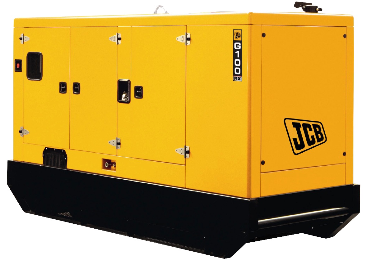
Generators
Part Number Machine Model Serial Numbers
JCB Generators 1204000 – 1212000
JCB Generators 1650000 onwards
…
JCB Generators
Part Number Machine Model Serial Numbers
Schematics 1204000 – 1212000
Engines 1204000 – 1212000
Alternators 1204000 – 1212000
Control Panels 1204000 – 1212000
…
JCB Generators
Part Number Machine Model Serial Numbers
Schematics 1650000 onwards
Engines 1650000 onwards
Alternators 1650000 onwards
Control Panels 1650000 onwards
Operator Manuals 1650000 onwards
…
Schematics
Part Number Machine Model Serial Numbers
Deutz 1204000 – 1212000
Dieselmax 1204000 – 1212000
Sisu 1204000 – 1212000
Scania 1204000 – 1212000
…
Service Manual
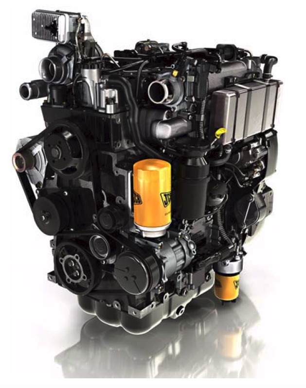
Engines
Part Number Machine Model Serial Numbers
SISU Diesel 320/420/620/634 – English 1204000 – 1212000
SISU Diesel 320/420/620/634 – RTS 1204000 – 1212000
Part Number Machine Model Serial Numbers
Scania Diesel -Work Desc – 09 Engine – English 1204000 – 1212000
Scania Diesel -Work Desc – 12 Engine – English 1204000 – 1212000
Scania Diesel -Work Desc – 16 Engine – English 1204000 – 1212000
Scania Diesel – Cooling system – English 1204000 – 1212000
Scania Diesel – Fuel system – English 1204000 – 1212000
Part Number Machine Model Serial Numbers
JCB Dieselmax – English 1204000 – 1212000
Part Number Machine Model Serial Numbers
Deutz D2009 – English 1204000 – 1212000
…
Alternators
Part Number Machine Model Serial Numbers
BC Range- English 1204000 – 1212000 and
UC Range- English 1650000 onwards
HC Range- English
Fault Finding
Linz – English 1650000 onwards
…
Control Panel
Part Number Machine Model Serial Numbers
Easygen 1204000 – 1212000
LeoPC 1204000 – 1212000
…
Service Manual
Schematics
Part Number Machine Model Serial Numbers
LT9 1650000 Onwards
Yanmar 1650000 Onwards
Dieselmax 1650000 Onwards
Iveco 1650000 Onwards
Scania 1650000 Onwards
…
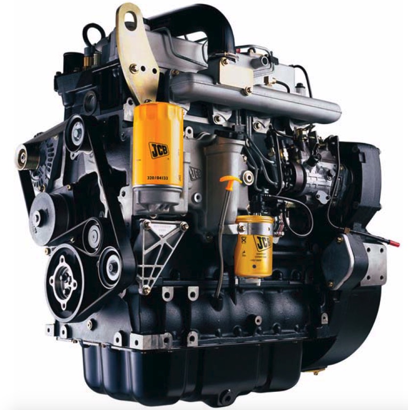
Service Manual
Engines
Part Number Machine Model Serial Numbers
Yanmar TNV – English 1650000 onwards
Scania Diesel -Work Desc – 09 Engine – English 1650000 onwards
Scania Diesel -Work Desc – 12 Engine – English 1650000 onwards
Scania Diesel -Work Desc – 16 Engine – English 1650000 onwards
Scania Diesel – Cooling system – English 1650000 onwards
Scania Diesel – Fuel system – English 1650000 onwards
JCB Dieselmax – English 1650000 onwards
Iveco N Series – English 1650000 onwards
…
Service Manual
Alternators
Part Number Machine Model Serial Numbers
BC Range- English 1204000 – 1212000 and
UC Range- English 1650000 onwards
HC Range- English
Fault Finding
Linz – English 1650000 onwards
…
Service Manual
Control Panel
Part Number Machine Model Serial Numbers
CP1/CP2 1650000 Onwards
KS1 1650000 Onwards
…
Operator Manuals
JCB Generators
Part Number Machine Model Serial Numbers
9811/4550 8X TO G45QX – English 1650000 onwards
9811/4551 8X TO G45QX – French 1650000 onwards
9811/4552 8X TO G45QX – German 1650000 onwards
9811/4553 8X TO G45QX – Spanish 1650000 onwards
9811/4555 8X TO G45QX – Portuguese 1650000 onwards
9811/4556 8X TO G45QX – Dutch 1650000 onwards
9811/4566 8X TO G45QX – Russian 1650000 onwards
9811/4600 G60RX TO G115QX – English 1650000 onwards
9811/4601 G60RX TO G115QX – French 1650000 onwards
9811/4602 G60RX TO G115QX – German 1650000 onwards
9811/4603 G60RX TO G115QX – Spanish 1650000 onwards
9811/4605 G60RX TO G115QX – Portuguese 1650000 onwards
9811/4606 G60RX TO G115QX – Dutch 1650000 onwards
9811/4616 G60RX TO G115QX – Russian 1650000 onwards
9811/4650 G130RX TO G220QX – English 1650000 onwards
9811/4651 G130RX TO G220QX – French 1650000 onwards
9811/4652 G130RX TO G220QX – German 1650000 onwards
9811/4653 G130RX TO G220QX – Spanish 1650000 onwards
9811/4655 G130RX TO G220QX – Portuguese 1650000 onwards
9811/4656 G130RX TO G220QX – Dutch 1650000 onwards
9811/4666 G130RX TO G220QX – Russian 1650000 onwards
9811-4700 G250RX TO G600X – English 1650000 onwards
9811-4701 G250RX TO G600X – French 1650000 onwards
9811-4702 G250RX TO G600X – German 1650000 onwards
9811-4703 G250RX TO G600X – Spanish 1650000 onwards
9811-4705 G250RX TO G600X – Portuguese 1650000 onwards
9811-4706 G250RX TO G600X – Dutch 1650000 onwards
9811-4716 G250RX TO G600X – Russian 1650000 onwards
9811-5050 LIGHTING TOWER LT9 – English 1650000 onwards
9811-5051 LIGHTING TOWER LT9 – French 1650000 onwards
9811-5052 LIGHTING TOWER LT9 – German 1650000 onwards
9811-5053 LIGHTING TOWER LT9 – Spanish 1650000 onwards
9811-5055 LIGHTING TOWER LT9 Portuguese 1650000 onwards
JCB Generators
Part Number Machine Model Serial Numbers
9811-5056 LIGHTING TOWER LT9 – Dutch 1650000 onwards
9811-5066 LIGHTING TOWER LT9 – Russian 1650000 onwards
9811-9050 BUSINESS SOLUTIONS – English 1650000 onwards
9811-9051 BUSINESS SOLUTIONS – French 1650000 onwards
…
EXCERPT:
Before Removing
1 Ensure that the engine is safe to work on. If the engine has been running, make sure the engine has cooled sufficiently before you start.
2 Drain the coolant, see Section 3 Routine Maintenance.
Removal
1 Disconnect the radiator hose at the thermostat housing 1-1.
2 Undo the bolts 1-2 and lift off the housing 1-1.
3 Lift out the thermostat 2-3.
If the thermostat is suspected of being faulty, perform tests to confirm its serviceability, see Section 6 Test Procedures. Note that the thermostat is a non serviceable item. If the thermostat is faulty or damaged it must be renewed.
Replacement
Replacement is the reverse of removal but note the following:
…